2018 Alfa Romeo Stelvio display
[x] Cancel search: displayPage 74 of 276
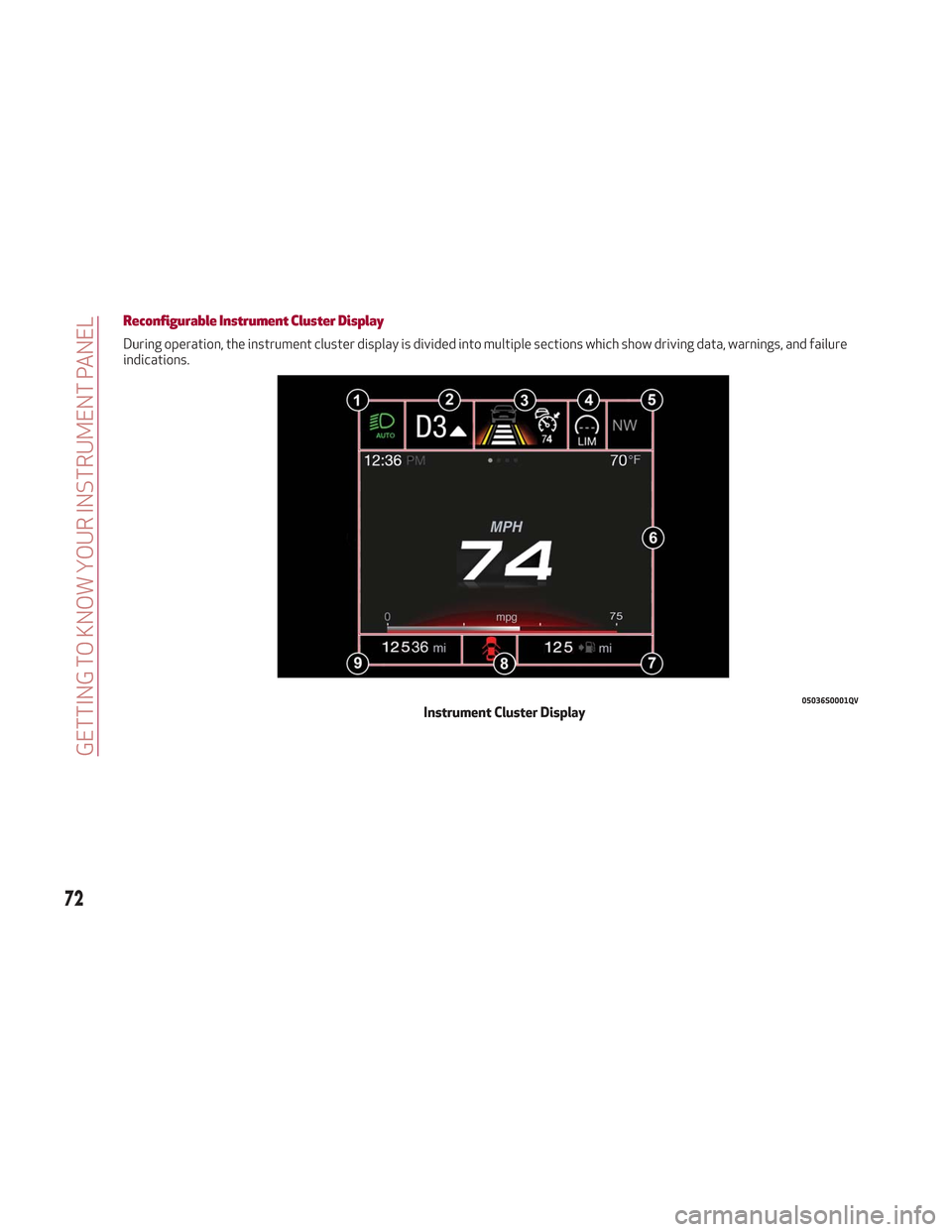
Reconfigurable Instrument Cluster Display
During operation, the instrument cluster display is divided into multiple sections which show driving data, warnings, and failure
indications.
05036S0001QVInstrument Cluster Display
72
GETTING TO KNOW YOUR INSTRUMENT PANEL
Page 75 of 276

Reconfigurable Display Items
1.Headlight Warning Lights
Displays the headlight warning light for
either of the following active modes:
Headlights
Automatic Headlights
2. Gear Selector Information
Displays the following information
controlled by the gear selector function:
P = PARK
R = REVERSE
N = NEUTRAL
D= DRIVE, (automatic forward speed)
AutoStick: + shifting to higher gear in
manual (sequential) driving mode –
shifting to lower gear in sequential
driving mode
3. Forward Collision, Lane Departure,
Cruise Control
Displays operations for the following
modes:
Forward Collision Warning (FCW)
Lane Departure Warning (LDW)
Cruise Control (CC) or Active Cruise
Control (ACC) (if equipped) 4.
Speed Limit Warning Light
Shows information regarding the Speed
Limiter function.
5. Compass
6. Reconfigurable Main Area
Can display the following screens:
Home
Trip A
Trip B (can be activated/deactivated
through the Information and
Entertainment System)
Performance
The screens can be selected, on rotation,
by pushing the MENU selection button on
the windshield wiper stalk.
Depending on the driving mode chosen
using the Alfa DNA Pro (Dynamic, Natural,
Advanced Efficiency and RACE), the
screens can be graphically different. Navigation instructions and call
information can be set and displayed in
the Information and Entertainment
System.
Home
The parameters shown on the display for
the Dynamic, Natural and Advanced
Efficiency modes are:
Time
Outside Temperature
Current Speed (shown if the repeat
modes of the Phone and Navigation
functions are not active)
Range
05036V0002EMMENU Selection Button
05036S0004NAInstrument Cluster Display
73
Page 76 of 276
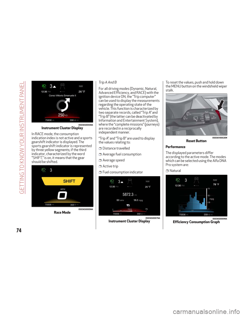
In RACE mode, the consumption
indication index is not active and a sports
gearshift indicator is displayed. The
sports gearshift indicator is represented
by three yellow segments; if the third
indicator, characterized by the word
"SHIFT,” is on, it means that the gear
should be shifted.Trip A And B
For all driving modes (Dynamic, Natural,
Advanced Efficiency, and RACE) with the
ignition device ON, the "Trip computer"
can be used to display the measurements
regarding the operating state of the
vehicle. This function is characterized by
two separate records, called “Trip A” and
“Trip B” (the latter can be deactivated by
Information and Entertainment System),
where the “complete missions” (journeys)
are recorded in a reciprocally
independent manner.
“Trip A” and “Trip B” are used to display
the values relating to:
Distance travelled
Average fuel consumption
Average speed
Active trip
Fuel consumption indicatorTo reset the values, push and hold down
the MENU button on the windshield wiper
stalk.
Performance
The displayed parameters differ
according to the active mode. The modes
which can be selected using the Alfa DNA
Pro system are:Natural
05036S0055NAInstrument Cluster Display
05036S0005NARace Mode
05036S0007NAInstrument Cluster Display
05036V0002EMReset Button
05036S0009NAEfficiency Consumption Graph
74
GETTING TO KNOW YOUR INSTRUMENT PANEL
Page 77 of 276
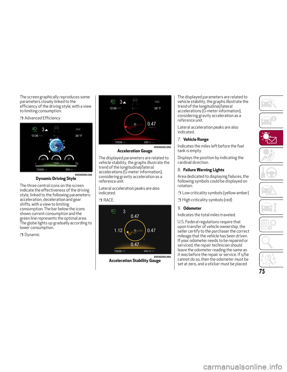
The screen graphically reproduces some
parameters closely linked to the
efficiency of the driving style, with a view
to limiting consumption.
Advanced Efficiency
The three central icons on the screen
indicate the effectiveness of the driving
style, linked to the following parameters:
acceleration, deceleration and gear
shifts, with a view to limiting
consumption. The bar below the icons
shows current consumption and the
green line represents the optimal area.
The globe lights up gradually according to
lower consumption.
Dynamic The displayed parameters are related to
vehicle stability, the graphs illustrate the
trend of the longitudinal/lateral
accelerations (G-meter information),
considering gravity acceleration as a
reference unit.
Lateral acceleration peaks are also
indicated.
RACEThe displayed parameters are related to
vehicle stability, the graphs illustrate the
trend of the longitudinal/lateral
accelerations (G-meter information),
considering gravity acceleration as a
reference unit.
Lateral acceleration peaks are also
indicated.
7.
Vehicle Range
Indicates the miles left before the fuel
tank is empty.
Displays the position by indicating the
cardinal direction.
8. Failure Warning Lights
Area dedicated to displaying failures, the
following symbols could be displayed on
rotation:
Low criticality symbols (yellow amber)
High criticality symbols (red)
9. Odometer
Indicates the total miles traveled.
U.S. Federal regulations require that
upon transfer of vehicle ownership, the
seller certify to the purchaser the correct
mileage that the vehicle has been driven.
If your odometer needs to be repaired or
serviced, the repair technician should
leave the odometer reading the same as
it was before the repair or service. If s/he
cannot do so, then the odometer must be
set at zero, and a sticker must be placed
05036S0011NADynamic Driving Style
05036S0013NAAcceleration Gauge
05036S0014NAAcceleration Stability Gauge
75
Page 79 of 276
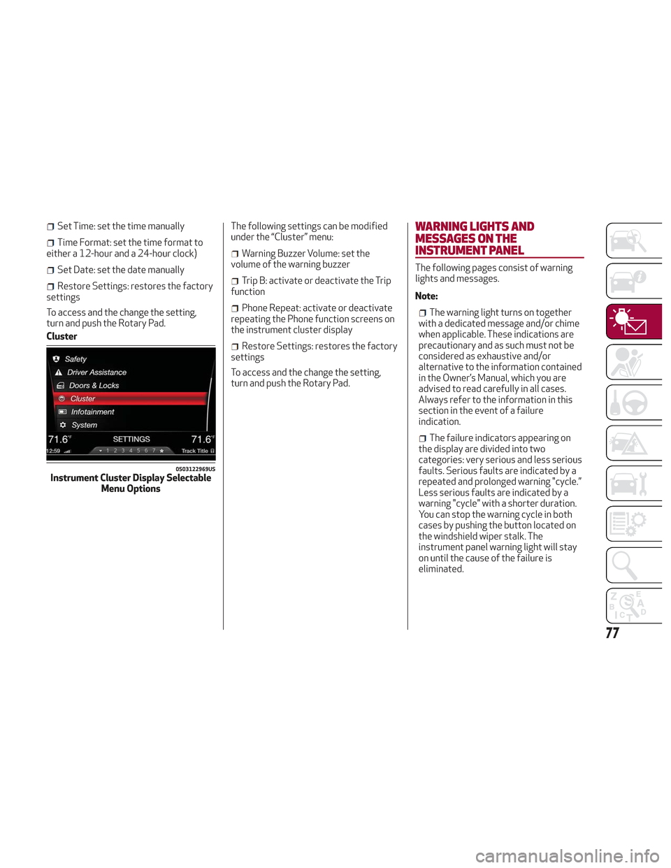
Set Time: set the time manually
Time Format: set the time format to
either a 12-hour and a 24-hour clock)
Set Date: set the date manually
Restore Settings: restores the factory
settings
To access and the change the setting,
turn and push the Rotary Pad.
Cluster The following settings can be modified
under the “Cluster” menu:
Warning Buzzer Volume: set the
volume of the warning buzzer
Trip B: activate or deactivate the Trip
function
Phone Repeat: activate or deactivate
repeating the Phone function screens on
the instrument cluster display
Restore Settings: restores the factory
settings
To access and the change the setting,
turn and push the Rotary Pad.
WARNING LIGHTS AND
MESSAGES ON THE
INSTRUMENT PANEL
The following pages consist of warning
lights and messages.
Note:
The warning light turns on together
with a dedicated message and/or chime
when applicable. These indications are
precautionary and as such must not be
considered as exhaustive and/or
alternative to the information contained
in the Owner’s Manual, which you are
advised to read carefully in all cases.
Always refer to the information in this
section in the event of a failure
indication.
The failure indicators appearing on
the display are divided into two
categories: very serious and less serious
faults. Serious faults are indicated by a
repeated and prolonged warning "cycle.”
Less serious faults are indicated by a
warning "cycle" with a shorter duration.
You can stop the warning cycle in both
cases by pushing the button located on
the windshield wiper stalk. The
instrument panel warning light will stay
on until the cause of the failure is
eliminated.
0503122969USInstrument Cluster Display Selectable Menu Options
77
Page 81 of 276

Warning LightWhat It Means What To Do
AIR BAG WARNING LIGHT
This light will turn on for four to eight seconds as a bulb
check when the ignition is placed in the ON/RUN position.
If the light is either not on during startup, stays on, or
turns on while driving, have the system inspected at an
authorized dealer as soon as possible. This light will
illuminate with a single chime when a fault with the Air
Bag Warning Light has been detected, it will stay on until
the fault is cleared. If the light comes on intermittently or
remains on while driving, have an authorized dealer
service the vehicle immediately.If the problem persists, contact an authorized dealer.
SEAT BELT REMINDER WARNING LIGHT
When the ignition is first placed in the ON/RUN position,
if the driver’s seat belt is unbuckled, a chime will sound
and the light will turn on. When driving, if the driver or
front passenger seat belt remains unbuckled, the Seat
Belt Reminder Light will flash or remain on continuously
and a chime will sound. Refer to “Occupant Restraints” in
“Safety” for further information.
Always wear your seat belt when operating the vehicle.
OIL TEMPERATURE WARNING LIGHT
This telltale indicates engine oil temperature is high.
Stop the vehicle and shut off the engine as soon as
possible. If the problem persists, contact an authorized
dealer.
Warning!
The fault of the warning light is signaled by the turning on of the icon on the instrument panel. In this case, the warning light may not indicate any
faults with the restraint systems. Before proceeding, contact an authorized dealer to have the system checked immediately.
If the warning light does not turn on when the ignition device is moved to ON or if it stays on when driving (together with the message on the
display), there might be a fault in the restraint systems; in this case, the air bags or pretensioners may not deploy in the event of an accident or, in a
lower number of cases, they could deploy erroneously. Before proceeding, contact an authorized dealer to have the system checked immediately.
79
Page 82 of 276
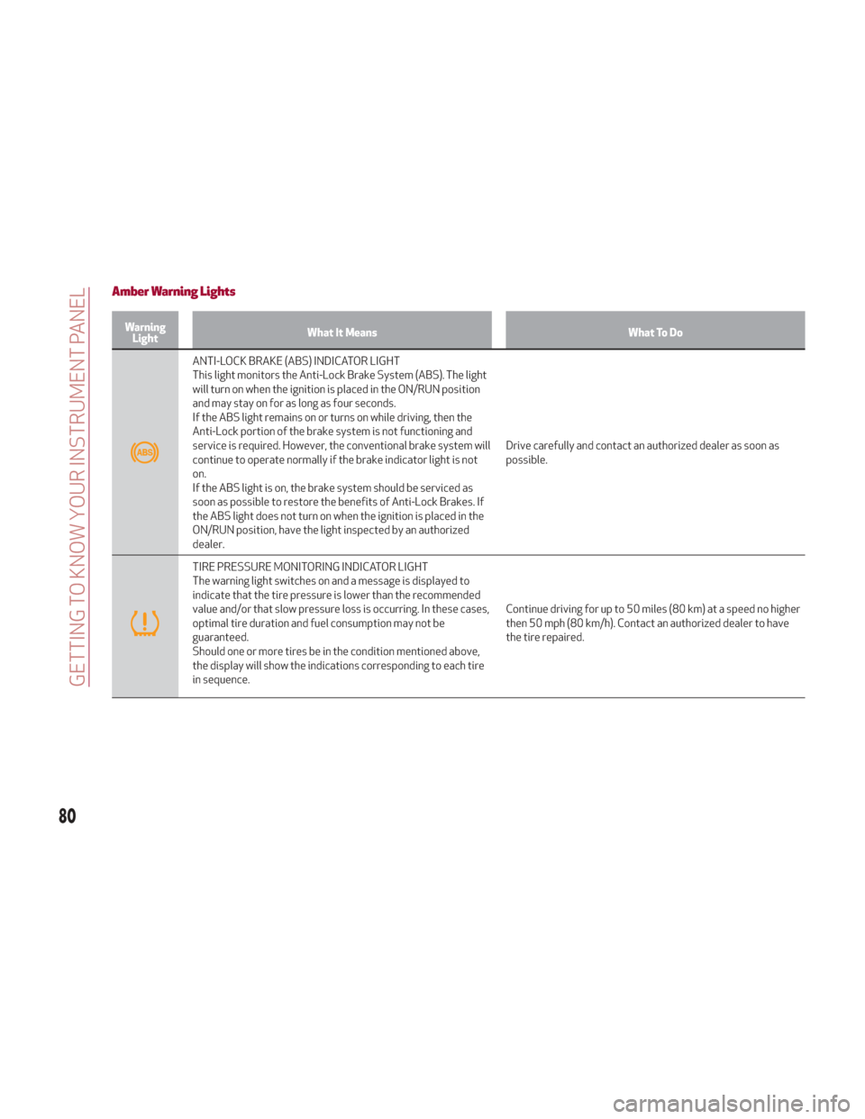
Amber Warning Lights
WarningLight What It Means What To Do
ANTI-LOCK BRAKE (ABS) INDICATOR LIGHT
This light monitors the Anti-Lock Brake System (ABS). The light
will turn on when the ignition is placed in the ON/RUN position
and may stay on for as long as four seconds.
If the ABS light remains on or turns on while driving, then the
Anti-Lock portion of the brake system is not functioning and
service is required. However, the conventional brake system will
continue to operate normally if the brake indicator light is not
on.
If the ABS light is on, the brake system should be serviced as
soon as possible to restore the benefits of Anti-Lock Brakes. If
the ABS light does not turn on when the ignition is placed in the
ON/RUN position, have the light inspected by an authorized
dealer. Drive carefully and contact an authorized dealer as soon as
possible.
TIRE PRESSURE MONITORING INDICATOR LIGHT
The warning light switches on and a message is displayed to
indicate that the tire pressure is lower than the recommended
value and/or that slow pressure loss is occurring. In these cases,
optimal tire duration and fuel consumption may not be
guaranteed.
Should one or more tires be in the condition mentioned above,
the display will show the indications corresponding to each tire
in sequence.
Continue driving for up to 50 miles (80 km) at a speed no higher
then 50 mph (80 km/h). Contact an authorized dealer to have
the tire repaired.
80
GETTING TO KNOW YOUR INSTRUMENT PANEL
Page 84 of 276
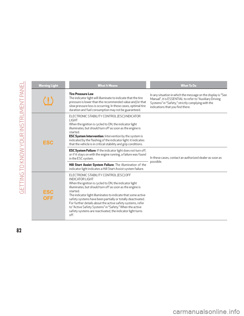
Warning LightWhat It Means What To Do
Tire Pressure Low
The indicator light will illuminate to indicate that the tire
pressure is lower than the recommended value and/or that
slow pressure loss is occurring. In these cases, optimal tire
duration and fuel consumption may not be guaranteed.In any situation in which the message on the display is "See
Manual", it is ESSENTIAL to refer to “Auxiliary Driving
Systems” in “Safety,” strictly complying with the
indications that you find there.
ELECTRONIC STABILITY CONTROL (ESC) INDICATOR
LIGHT
When the ignition is cycled to ON, the indicator light
illuminates, but should turn off as soon as the engine is
started.
ESC System Intervention
: Intervention by the system is
indicated by the flashing of the indicator light: it indicates
that the vehicle is in critical stability and grip conditions.
ESC System Failure : If the indicator light does not turn off,
or if it stays on with the engine running, a failure was found
in the ESC system. In these cases, contact an authorized dealer as soon as
possible.
Hill Start Assist System Failure : The illumination of the
indicator light indicates a Hill Start Assist system failure.
ELECTRONIC STABILITY CONTROL (ESC) OFF
INDICATOR LIGHT
When the ignition is cycled to ON, the indicator light
illuminates, but should turn off as soon as the engine is
started.
The indicator light illuminates to indicate that some active
safety systems have been partially or totally deactivated.
For further details about the active safety systems, refer
to “Active Safety Systems” in “Safety.” When the active
safety systems are reactivated, the indicator light turns
off.
82
GETTING TO KNOW YOUR INSTRUMENT PANEL