2018.5 OPEL AMPERA E service indicator
[x] Cancel search: service indicatorPage 66 of 273

64Instruments and controlsInstruments and
controlsControls ....................................... 65
Steering wheel adjustment ........65
Steering wheel controls .............65
Heated steering wheel ...............65
Horn ........................................... 66
Pedestrian safety alert ...............66
Windscreen wiper and washer ..66
Rear window wiper and washer ...................................... 68
Outside temperature ..................68
Clock ......................................... 69
Power outlets ............................. 69
Inductive charging .....................70
Warning lights, gauges and indi‐ cators ........................................... 72
Instrument cluster ......................72
Speedometer ............................. 74
Odometer .................................. 74
Battery gauge ............................ 74
Driving efficiency gauge ............74
Power indicator gauge ...............76
Regenerative braking ................76
Total vehicle range ....................77
Service display .......................... 77Control indicators ......................77
Turn lights .................................. 77
Seat belt reminder .....................77
Airbag and belt tensioners .........78
Airbag deactivation ....................78
Charging system .......................78
Service vehicle soon .................79
Brake system ............................. 79
Electric parking brake ................79
Electric parking brake fault ........79
Antilock brake system (ABS) .....79
Sport mode ................................ 80
Lane keep assist .......................80
Electronic Stability Control off ...80
Electronic Stability Control and Traction Control system ...........80
Traction Control system off .......80
Tyre pressure monitoring system ...................................... 80
Immobiliser ................................ 81
Vehicle ready ............................. 81
Exterior light .............................. 81
High beam ................................. 81
High beam assist .......................81
Rear fog light ............................. 81
Cruise control ............................ 81
Vehicle detected ahead .............81
Pedestrian detection ..................81
Speed limiter ............................. 81Traffic sign assistant ..................82
Door open .................................. 82
Displays ....................................... 82
Driver Information Centre ..........82
Info Display ................................ 85
Vehicle messages ........................89
Warning chimes .........................90
Battery voltage .......................... 90
Vehicle personalisation ................91
Telematics service .......................94
OnStar ....................................... 94
Page 79 of 273

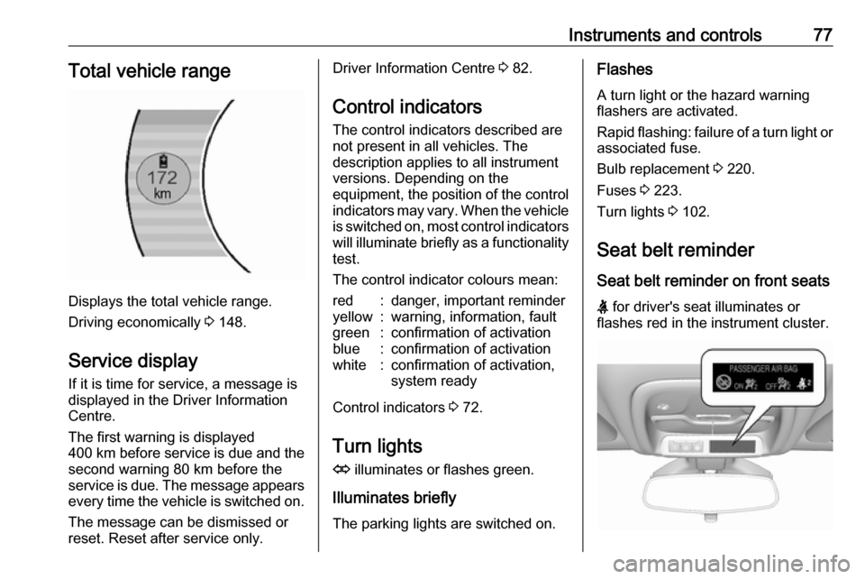
Instruments and controls77Total vehicle range
Displays the total vehicle range.
Driving economically 3 148.
Service display If it is time for service, a message is
displayed in the Driver Information
Centre.
The first warning is displayed
400 km before service is due and the
second warning 80 km before the
service is due. The message appears every time the vehicle is switched on.
The message can be dismissed or
reset. Reset after service only.
Driver Information Centre 3 82.
Control indicators
The control indicators described are
not present in all vehicles. The
description applies to all instrument
versions. Depending on the
equipment, the position of the control indicators may vary. When the vehicle
is switched on, most control indicators
will illuminate briefly as a functionality test.
The control indicator colours mean:red:danger, important reminderyellow:warning, information, faultgreen:confirmation of activationblue:confirmation of activationwhite:confirmation of activation,
system ready
Control indicators 3 72.
Turn lights
O illuminates or flashes green.
Illuminates briefly
The parking lights are switched on.
Flashes
A turn light or the hazard warning
flashers are activated.
Rapid flashing: failure of a turn light or associated fuse.
Bulb replacement 3 220.
Fuses 3 223.
Turn lights 3 102.
Seat belt reminder
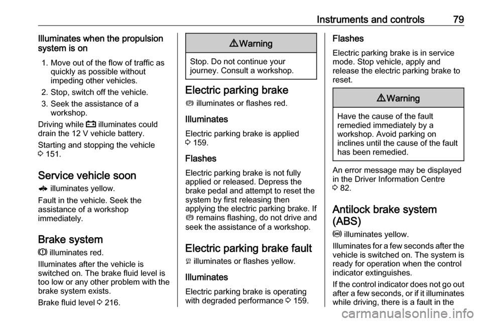
Seat belt reminder on front seats
X for driver's seat illuminates or
flashes red in the instrument cluster.
Page 81 of 273

Instruments and controls79Illuminates when the propulsion
system is on
1. Move out of the flow of traffic as quickly as possible without
impeding other vehicles.
2. Stop, switch off the vehicle.
3. Seek the assistance of a workshop.
Driving while p illuminates could
drain the 12 V vehicle battery.
Starting and stopping the vehicle
3 151.
Service vehicle soon 6 illuminates yellow.
Fault in the vehicle. Seek the
assistance of a workshop
immediately.
Brake system
R illuminates red.
Illuminates after the vehicle is
switched on. The brake fluid level is
too low or any other problem with the
brake system exists.
Brake fluid level 3 216.9 Warning
Stop. Do not continue your
journey. Consult a workshop.
Electric parking brake
m illuminates or flashes red.
Illuminates
Electric parking brake is applied
3 159.
Flashes
Electric parking brake is not fully applied or released. Depress the
brake pedal and attempt to reset the system by first releasing then
applying the electric parking brake. If
m remains flashing, do not drive and
seek the assistance of a workshop.
Electric parking brake fault
j illuminates or flashes yellow.
Illuminates
Electric parking brake is operating
with degraded performance 3 159.
Flashes
Electric parking brake is in service
mode. Stop vehicle, apply and
release the electric parking brake to
reset.9 Warning
Have the cause of the fault
remedied immediately by a
workshop. Avoid parking on
inclines until the cause of the fault has been remedied.
An error message may be displayed
in the Driver Information Centre
3 82.
Antilock brake system
(ABS)
u illuminates yellow.
Illuminates for a few seconds after the
vehicle is switched on. The system is ready for operation when the control
indicator extinguishes.
If the control indicator does not go out after a few seconds, or if it illuminates
while driving, there is a fault in the
Page 152 of 273

150Driving and operatingIf the vehicle will not start, place the
electronic key in the transmitter
pocket inside the centre console.
Starting and stopping the vehicle
3 151.Switching on the vehicle
With the vehicle off and the brake
pedal applied, pressing POWERm
once will switch on the vehicle. When 4 illuminates in the instrument
cluster, the vehicle is ready to be
driven. This could take up to
15 seconds at extremely cold
temperatures.Switching off the vehicle
With the vehicle in P, press
POWER m briefly in service mode or
when engine is running and vehicle is
stationary. Some functions remain
active until driver's door is opened.
If the vehicle is not in P when
switching off the vehicle, P will be
automatically engaged before the
vehicle is switched off.A chime will sound if the driver's door is opened while the vehicle is
switched on. Always press
POWER m to switch off the vehicle
before exiting the vehicle.Emergency shut off during driving
If the vehicle needs to be switched off during driving in case of emergency,
press POWER m for more than
2 seconds or press twice briefly within
5 seconds.
Starting and stopping the vehicle
3 151.
Service mode
This power mode is available for
service and diagnostics and to verify
the proper operation of the service
vehicle soon control indicator as may
be required for emission inspection
purposes.
With the vehicle switched off and the
brake pedal not applied, pressing and holding POWER m for more than
5 seconds will place the vehicle in service mode. The instruments and
audio systems will operate as they do when the vehicle is switched on, but
the vehicle will not be able to be
driven. The propulsion system will not start in service mode. Press
POWER m again to switch off the
vehicle.Caution
Service mode will discharge the
12 V vehicle battery. Do not use
service mode for an extended
period, or the vehicle may not
start.
Operation in case of failure
If the vehicle does not start due to a
low electronic key battery, a message
will be displayed in the Driver
Information Centre.
To still drive the vehicle, proceed as
follows:
1. Open the centre console and remove the small tray from the
centre console. Place the
electronic key in the pocket with
the buttons facing the bottom of
the vehicle.
Page 207 of 273

Driving and operating205● Solid green – No horn chirps:Charging is complete.
● Solid yellow – No horn chirp: Vehicle is plugged in. It is normalfor the charging status indicator
to turn yellow for a few seconds
after plugging in a compatible
charge cord. The solid yellow
may remain illuminated
depending on the vehicle.
This may also indicate that the
charging system has detected a
fault and will not charge the high
voltage battery.
● No light signal (upon plug‐in) – No horn chirps: Charge cord
connection should be checked.
● No light signal (after indication of
green or yellow charging status
indicator) – No horn chirps:
Charge cord connection should
be checked. If connection is
correct, this may be due to a
power failure and charging will
begin later. This may also occur
if the vehicle has detected a high voltage charging system fault.● No light signal – Three horn chirps: Charge port door is open.
● No light signal – Horn chirps repeatedly: The power supply
was interrupted before the
charging process could be
completed. Repeated chirps will stop if power is restored within
90 seconds.
Vehicle personalisation 3 91.
The system may be thermally
conditioning the high voltage battery
during any of the states mentioned
above, requiring electric energy to be
transferred to the vehicle.
If the vehicle is plugged in and vehicle power is on, the charging status
indicator will flash or illuminate solid green, depending on the charge level.
This also happens during Engine
Assisted Heating if the vehicle is
plugged in.
If the vehicle is plugged in and the
charging status indicator is off, a
charging fault has been detected.Charge cord9 Danger
There is a risk of electric shock
that may cause personal injury or
death.
Do not use the charge cord if any part of the charge cord is
damaged.
Do not open or remove the charge cord cover.
Service by qualified personnel
only. Connect the charge cord to a
properly grounded outlet with
cords that are not damaged.
A portable charge cord used to
charge the vehicle high voltage
battery is stored under the rear floor
storage cover in the load
compartment 3 194.
Page 209 of 273

Driving and operating207installations in buildings,
depending on the region in which
the unit is being installed. The
installer shall comply with any
additional local requirements
mandated by the country and / or
municipality.
Do not use this product if the
flexible power cord or the electric
vehicle cable is frayed, has broken insulation, or shows any other
signs of damage.
Do not use this product if the
enclosure or the vehicle plug is
broken, cracked, open, or shows
any other indication of damage.
The plug must be plugged into an
appropriate electrical outlet that is
properly installed in accordance
with all local codes and
ordinances. Do not modify the
plug provided with the product. If
the plug does not fit the electrical
outlet, have a proper electrical
outlet installed by a qualified
electrician. If ground is missing,the charge cord indicators will
indicate an electrical system fault
and the vehicle may not charge.
1. Vehicle plug
2. Protective cover
3. Status indicators
4. Wall plug
Charge cord status indicators
After plugging in the charge cord, it
will perform a quick self test.
Verify the charge cord status.
● c illuminates green and d is off,
the charge cord is ready to
charge the vehicle.
● c flashing green and d is off:
Electrical outlet / plug fault: The
charge cord has detected that the electrical outlet / plug
overheated. Use another
electrical outlet or have the
electrical outlet serviced by a
qualified electrician. Reset the
charge cord by unplugging the
charge cord from the electrical
outlet and re-plugging it.
● c is off and d flashes red:
Vehicle fault: The charge cord
ground-fault circuit interrupter
has tripped. Ensure that there is no physical damage to the
charge cord and that the vehicle
plug is seated completely and making a good connection. Reset
the charge cord by unplugging
Page 210 of 273

208Driving and operatingfrom the electrical outlet and re-
plugging it. If the fault remains,
consult a workshop for a service.
● c solid green and d flashes red:
charge cord fault: The charge cord has detected a potential
problem with the charge cord.
Reset the charge cord by
unplugging from the electrical
outlet and re-plugging it. If the fault remains, seek the
assistance of a workshop.
If no status indicator is lit, ensure the
electrical outlet is powered.
Charge level selection9 Warning
If the capacity of the electrical
circuit or AC socket is not known,
only use the lowest charge level
until the circuit capacity has been
inspected by a qualified
electrician. Using a charge level
that exceeds either the electrical
circuit or the AC outlet capacity
may start a fire or damage the
electrical circuit.
Note
By choosing a reduced charge level,
the charging time is increased.
Charge limit selection can be made
using the Charge limit preference
screen on the Info Display.
Charge limit selection 3 197.
Grounding instructions This product must be grounded. If this
product should malfunction or break
down, grounding provides a path of
least resistance for electric current to
reduce the risk of electric shock. This product is equipped with a cord that
has an equipment grounding
conductor and a grounding plug. The
plug must be plugged into an
appropriate outlet that is properly
installed and grounded in accordance
with all local codes and ordinances.9 Warning
Improper connection of the charge
cord ground may cause electrical
shock. Check with a qualified
electrician if there is doubt as to
whether the charge circuit is
properly grounded. Do not modify
the plug provided with the product.
If it will not fit the electrical outlet,
have a proper electrical outlet
installed by a qualified electrician.
Charge cord mounting
instructions
Choose an appropriate, solid location for mounting the charge cord. The
appropriate height for mounting the
charge cord is 91 cm from the floor.
Space the holes 18.7 cm apart.
Install the mounting screws leaving
the head of the screws 5 mm from the
surface.
Securely mount the charge cord on to
the screws.
Connect the wall plug to the electrical
outlet.
Connect the vehicle plug to the
charge port.
Page 237 of 273

Vehicle care235replacement or alternative tyres and
wheels allow the tyre pressure
monitoring system to continue to
function properly.
A spare wheel is not equipped with a pressure sensor. The tyre pressure
monitoring system is not operational
for these wheels. Control indicator w
illuminates. For the further three
wheels the system remains
operational.
The use of commercially-available
liquid tyre repair kits can impair the
function of the system. Factory-
approved repair kits can be used.
Operating electronic devices or being
close to facilities using similar wave
frequencies could disrupt the tyre
pressure monitoring system.
Each time the tyres are replaced, tyre pressure monitoring system sensors
must be dismounted and serviced.
For the screwed sensor, replace
valve core and sealing ring. For the
clipped sensor, replace complete
valve stem.Vehicle loading status
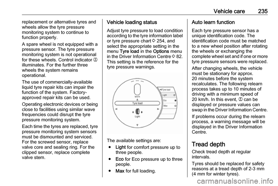
Adjust tyre pressure to load condition
according to the tyre information label or tyre pressure chart 3 254, and
select the appropriate setting in the
menu Tyre load in the Options menu
in the Driver Information Centre 3 82.
This setting is the reference for the
tyre pressure warnings.
The available settings are:
● Light for comfort pressure up to
three people.
● Eco for Eco pressure up to three
people.
● Max for full loading.
Auto learn function
Each tyre pressure sensor has a
unique identification code. The
identification code must be matched
to a new wheel position after rotating
the wheels or exchanging the
complete wheel set and if one or more
tyre pressure sensors were replaced.
After changing wheels, the vehicle
must be stationary for approx.
20 minutes before the system
recalculates. The following relearn
process takes up to 10 minutes of
driving with a minimum speed of
20 km/h. In this event, w can be
displayed or pressure values can
swap in the Driver Information Centre.
If problems occur during the relearn
process, a warning message will be
displayed in the Driver Information
Centre.
Tread depthCheck tread depth at regular
intervals.
Tyres should be replaced for safety
reasons at a tread depth of 2-3 mm
(4 mm for winter tyres).