Page 307 of 432
CRANKSHAFT ASSEMBLY AND BALANCER SHAFT
6-78
EAS2GBB317
CRANKSHAFT ASSEMBLY AND BALANCER SHAFT
Removing the crankshaft assembly and balancer shaft
Order Part name Q’ty Remarks
CrankcaseSeparate.
Refer to “CRANKCASE” on page 6-72.
Transmission Refer to “TRANSMISSION” on page 6-81.
1 Balancer shaft 1
2 Crankshaft assembly 1
For installation, reverse the removal proce-
dure.
M
M
1
2
Page 310 of 432
TRANSMISSION
6-81
EAS2GBB322
TRANSMISSION
Removing the transmission, shift drum assembly, and shift forks
Order Part name Q’ty Remarks
Engine Refer to “ENGINE REMOVAL” on page 6-1.
CrankcaseSeparate.
Refer to “CRANKCASE” on page 6-72.
1 Main axle 1
2 Drive axle 1
3 Long shift fork guide bar 1
4 Short shift fork guide bar 1
5Spring 4
6 Shift cam 1
7 Shift fork 3 (R) 1
8 Shift fork 2 (C) 1
9 Shift fork 1 (L) 1
10 Collar 1
For installation, reverse the removal proce-
dure.
2
10
1
53
4 578
69
M
M
M
M
EE
E
E
LS
New
M
Page 311 of 432
TRANSMISSION
6-82
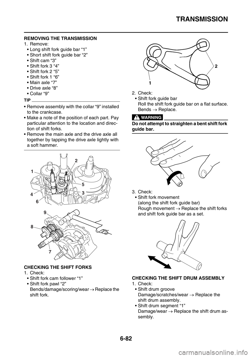
EAS2GBB323REMOVING THE TRANSMISSION
1. Remove:
• Long shift fork guide bar “1”
• Short shift fork guide bar “2”
• Shift cam “3”
• Shift fork 3 “4”
• Shift fork 2 “5”
• Shift fork 1 “6”
• Main axle “7”
• Drive axle “8”
• Collar “9”
TIP
• Remove assembly with the collar “9” installed
to the crankcase.
• Make a note of the position of each part. Pay
particular attention to the location and direc-
tion of shift forks.
• Remove the main axle and the drive axle all
together by tapping the drive axle lightly with
a soft hammer.
EAS2GBB324CHECKING THE SHIFT FORKS
1. Check:
• Shift fork cam follower “1”
• Shift fork pawl “2”
Bends/damage/scoring/wear Replace the
shift fork.2. Check:
• Shift fork guide bar
Roll the shift fork guide bar on a flat surface.
Bends Replace.
EWA
WARNING
Do not attempt to straighten a bent shift fork
guide bar.
3. Check:
• Shift fork movement
(along the shift fork guide bar)
Rough movement Replace the shift forks
and shift fork guide bar as a set.
EAS2GBB325CHECKING THE SHIFT DRUM ASSEMBLY
1. Check:
• Shift drum groove
Damage/scratches/wear Replace the
shift drum assembly.
• Shift drum segment “1”
Damage/wear Replace the shift drum as-
sembly.
1
4
62
5
3
8
7
9
Page 312 of 432

TRANSMISSION
6-83
EAS2GBB326CHECKING THE TRANSMISSION
1. Measure:
• Main axle runout
(with a centering device and dial gauge “1”)
Out of specification Replace the main ax-
le.
2. Measure:
• Drive axle runout
(with a centering device and dial gauge “1”)
Out of specification Replace the drive ax-
le.3. Check:
• Transmission gears
Blue discoloration/pitting/wear Replace
the defective gear (s).
• Transmission gear dogs
Cracks/damage/rounded edges Replace
the defective gear (s).
4. Check:
• Transmission gear movement
Rough movement Replace the defective
gear (s).EAS2GBB327INSTALLING THE TRANSMISSION
1. Install:
• 6th pinion gear (27T) “1”
• 3rd/4th pinion gear (18T/21T) “2”
• Collar “3”
• 5th pinion gear (23T) “4”
• 2nd pinion gear (16T) “5”
(to the main axle “6”)
TIP
Before installation, apply molybdenum disulfide
oil to the inner and end surface of the idler gear
and to the inner surface of the sliding gear, then
install.
2. Install:
• 2nd wheel gear (29T) “1”
• 5th wheel gear (22T) “2”
• 3rd wheel gear (26T) “3”
• 4th wheel gear (24T) “4”
• 6th wheel gear (22T) “5”
• Collar “6”
• 1st wheel gear (31T) “7”
• O-ring “8”
(to the drive axle “9”)
TIP
• Before installation, apply molybdenum disul-
fide oil to the inner and end surface of the idler
gear and the collar and to the inner surface of
the sliding gear, then install.
• Apply the lithium-soap-based grease on the
O-ring. Main axle runout limit
0.08 mm (0.0032 in)
Drive axle runout limit
0.08 mm (0.0032 in)
34
2
1
6
5
M
New
Page 313 of 432

TRANSMISSION
6-84
3. Install:
• Washer “1”
• Circlip “2”
TIP
• Be sure the circlip sharp-edged corner “a” is
positioned opposite side to the washer and
gear “b”.
• Install the circlip with its ends “c” settled even-
ly on the spline crests.
4. Install:
• Collar “1”
TIP
• Apply the lithium-soap-based grease on the
oil seal lip.
• When installing the collar into the crankcase,
pay careful attention to the crankcase oil seal
lip.5. Install:
• Main axle “1”
• Drive axle “2”
TIP
• Install to the left crankcase simultaneously.
• Apply engine oil to the main axle and the drive
axle bearing.
6. Install:
• Shift fork 1 (L) “1”
• Shift fork 2 (C) “2”
• Shift fork 3 (R) “3”
• Shift cam “4”
(to the main axle and the drive axle)
TIP
• Apply engine oil to the shift fork grooves.
• Apply engine oil to the shift cam groove and
the bearing contact surface.
• Mesh the shift fork 1 (L) with the 5th wheel
gear “5” and shift fork 3 (R) with the 6th wheel
gear “7” on the drive axle.
• Mesh the shift fork 2 (C) with the 3rd/4th pin-
ion gear “6” on the main axle.
891
234
567
New
LS
M
M
New
21
2
ab
cc
1
2
EE
Page 314 of 432
TRANSMISSION
6-85
7. Install:
• Long shift fork guide bar “1”
• Short shift fork guide bar “2”
• Spring “3”
TIP
• Screw the spring into the shift fork guide bar
lightly beforehand.
• Apply the engine oil on the shift fork guide
bars.8. Check:
• Operation of shift cam and shift fork
• Transmission operation
Unsmooth operation Repair.
3
12
6
2
4
5
3
7
1
E
E
E
2 13
E
Page 344 of 432
ELECTRIC STARTING SYSTEM
9-8
EAS2GBB361STARTING CIRCUIT CUT-OFF SYSTEM OPERATION
If the meter light comes on, the starter motor can only operate if at least one of the following condi-
tions is met:
• The transmission is in neutral (the neutral switch is closed).
• The clutch lever is pulled to the handlebar (the clutch switch is closed).
The starting circuit cut-off relay prevents the starter motor from operating when neither of these con-
ditions has been met. In this instance, the starting circuit cut-off relay is open so current cannot reach
the starter motor. When at least one of the above conditions has been met the starting circuit cut-off
relay is closed and the engine can be started by pressing the start switch.
Page 345 of 432
ELECTRIC STARTING SYSTEM
9-9
a. WHEN THE TRANSMISSION IS IN NEU-
TRAL
b. WHEN THE CLUTCH LEVER IS PULLED
TO THE HANDLEBAR
1. Battery
2. Main fuse
3. Main relay
4. Starting circuit cut-off relay
5. Start switch
6. Diode
7. Clutch switch
8. Neutral switch
9. Starter relay
10.Starter motor


