2017 YAMAHA VIKING brake light
[x] Cancel search: brake lightPage 73 of 172

6-4
6
Shifting: neutral to reverse
WARNING
EWB03300Before you shift into reverse, make sure
there are no obstacles or people behind
you. When it is safe to proceed, go slowly.
Hitting an obstacle or person could result
in serious injury or death. 1. Stop the vehicle, take your foot off the ac-celerator pedal, and check behind you.
2. Apply the brake pedal.
3. Shift from neutral to reverse or vice versa by moving the drive select lever along the
shift guide.
When in reverse, the reverse indicator
light should be on. If the light does not
come on, ask a Yamaha dealer to in-
spect the reverse indicator light electri-
cal circuit.
Due to the synchronizing mechanism in
the engine, the light may not come on
until the vehicle starts moving. 4. Release the parking brake, if applied.
5. Check behind the vehicle for people or
obstacles, and then release the brake
pedal.
6. Press the accelerator pedal gradually and
continue to watch to the rear while back-
ing.
1. Drive select lever
2. L (Low-range)
3. H (High-range)
4. N (Neutral)
5. R (Reverse)
1
2
5 4
3
UB427BE0.book Page 4 Friday, February 5, 2016 2:14 PM
Page 137 of 172

8-38
8
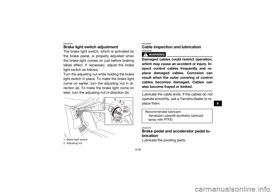
EBU32550Brake light switch adjustmentThe brake light switch, which is activated by
the brake pedal, is properly adjusted when
the brake light comes on just before braking
takes effect. If necessary, adjust the brake
light switch as follows.
Turn the adjusting nut while holding the brake
light switch in place. To make the brake light
come on earlier, turn the adjusting nut in di-
rection (a). To make the brake light come on
later, turn the adjusting nut in direction (b).
EBU35930Cable inspection and lubrication
WARNING
EWB03380Damaged cables could restrict operation,
which may cause an accident or injury. In-
spect control cables frequently and re-
place damaged cables. Corrosion can
result when the outer covering of control
cables becomes damaged. Cables can
also become frayed or kinked. Lubricate the cable ends. If the cables do not
operate smoothly, ask a Yamaha dealer to re-
place them.EBU32570Brake pedal and accelerator pedal lu-
bricationLubricate the pivoting parts.
1. Brake light switch
2. Adjusting nut
1(a)
(b)
2
Recommended lubricant: Yamalube LubezAll (synthetic lubricant
spray with PTFE)
UB427BE0.book Page 38 Friday, February 5, 2016 2:14 PM
Page 152 of 172

8-53
8
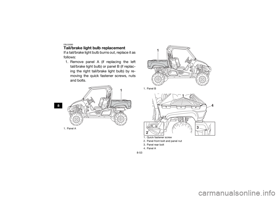
EBU32690Tail/brake light bulb replacementIf a tail/brake light bulb burns out, replace it as
follows:1. Remove panel A (if replacing the left
tail/brake light bulb) or panel B (if replac-
ing the right tail/brake light bulb) by re-
moving the quick fastener screws, nuts
and bolts.1. Panel A
1
1. Panel B
1. Quick fastener screw
2. Panel front bolt and panel nut
3. Panel rear bolt
4. Panel A
1
3
4
2 1
UB427BE0.book Page 53 Friday, February 5, 2016 2:14 PM
Page 153 of 172

8-54
8
2. Remove the tail/brake light bulb holder(together with the bulb) by turning it
counterclockwise.
3. Push the burnt-out bulb in and turn it counterclockwise to remove it from the
bulb holder.
4. Push a new bulb in and turn it clockwise to install in the bulb holder.
5. Install the bulb holder (together with the
bulb) by turning it clockwise.
6. Install the panel. 7. Install the quick fastener screws, bolts,
and nuts, and then tighten the panel nuts
and the panel rear bolt to the specified
torques.
EBU32700TroubleshootingAlthough Yamaha vehicles receive an inspec-
tion before shipment from the factory, trouble
may occur during operation. Any problem in
the fuel, compression, or ignition systems can
cause poor starting and loss of power. The
troubleshooting chart describes a quick, easy
procedure for making checks. If your vehicle
requires any repair, take it to a Yamaha deal-
er.
1. Tail/brake light bulb holder
1
Tightening torques:Panel nut:7 Nm (0.7 m·kgf, 5.1 ft·lbf)
Panel rear bolt: 4.0 Nm (0.40 m·kgf, 2.9 ft·lbf)
UB427BE0.book Page 54 Friday, February 5, 2016 2:14 PM
Page 163 of 172

10-4
10
Rear:120.0 kPa (1.200 kgf/cm², 17 psi)
Front wheel:Wheel type:
Cast wheel (YXM70VPSH)
Panel wheel (YXM70VPHH, YXM70VPXH)
Rim size:
12 x 6.0AT (YXM70VPSH)
12 x 7.5AT (YXM70VPHH, YXM70VPXH)Rear wheel:Wheel type:Cast wheel (YXM70VPSH)
Panel wheel (YXM70VPHH, YXM70VPXH)
Rim size: 12 x 7.5ATFront brake:Type:
Hydraulic disc brake
Operation: Unified brake
Specified brake fluid: DOT 4Rear brake:Type:Hydraulic disc brake
Operation: Unified brake
Specified brake fluid:
DOT 4
Front suspension:Type:Double wishbone
Spring/shock absorber type:
Coil spring/gas-oil damper
Wheel travel: 205 mm (8.1 in)Rear suspension:Type:
Double wishbone
Spring/shock absorber type: Coil spring/gas-oil damper
Wheel travel: 205 mm (8.1 in)Electrical system:Ignition system:TCI
Charging system: AC magnetoBattery:Model:U1-H11L
Voltage, capacity: 12 V, 28.0 AhHeadlight(s):Bulb type:Halogen bulbBulb voltage, wattage × quantity:Headlight:
12 V, 35.0/35.0 W × 2
UB427BE0.book Page 4 Friday, February 5, 2016 2:14 PM
Page 164 of 172

10-5
10
Tail/brake light:12 V, 5.0/21.0 W × 2
Neutral indicator light: LED
Reverse indicator light:
LED
Coolant temperature warning light: LED
Engine trouble warning light: LED
Park indicator light:
LED
High-range indicator light: LED
Low-range indicator light: LED
Differential gear lock indicator light:
LED
EPS warning light: LED
Helmet/Seat belt indicator light: 14 V, 0.85 W × 2Fuses:Main fuse:
40.0 A
Fuel injection system fuse: 10.0 A
EPS fuse:
40.0 A
Headlight fuse: 15.0 A Signaling system fuse:
10.0 A
Ignition fuse: 10.0 A
Auxiliary DC jack fuse:
10.0 A
Backup fuse: 10.0 A
Four-wheel-drive motor fuse: 10.0 A
Radiator fan motor fuse:
25.0 A
EBU33221For Europe only
The figures quoted are emission levels and
are not necessarily safe working levels. Whilst
there is a correlation between the emission
and exposure levels, this cannot be used reli-
ably to determine whether or not further pre-
cautions are required. Factors that influence
the actual level of exposure of work-force in-
clude the characteristics of the work room,
the other sources of noise, etc. i.e. the num-
ber of machines and other adjacent process-
es, and the length of time for which an
UB427BE0.book Page 5 Friday, February 5, 2016 2:14 PM
Page 168 of 172

12-1
12
INDEX
AAccelerator pedal ......................................................... 4-12
Accelerator pedal, Pre-operation check ........................ 5-6
Air filter case/duct check hose, cleaning ..................... 8-30
Air filter element, cleaning ............................................ 8-25
Auxiliary DC jack .......................................................... 4-24
Axle boots .................................................................... 8-22BBasic guide for safe use ................................................. 7-1
Battery, Periodic maintenance ..................................... 8-42
Brake fluid level, checking ........................................... 8-34
Brake fluid, replacing ...................................................8-36
Brake light switch, adjusting ........................................ 8-38
Brake pedal .................................................................. 4-12
Brake pedal and accelerator pedal, lubrication ........... 8-38
Brake pedal, checking ................................................. 8-36
Brakes, Periodic maintenance ..................................... 8-33
Brakes, Pre-operation check ......................................... 5-3CCable, inspecting and lubrication ................................ 8-38
Cargo bed .................................................................... 4-21
Cleaning ......................................................................... 9-1
Control cables, Pre-operation check ............................. 5-8
Coolant, Periodic maintenance .................................... 8-21
Coolant, Pre-operation check ........................................ 5-6
Coolant temperature warning light ................................. 4-4
Cup holders .................................................................. 4-20DDifferential gear oil, Periodic maintenance .................. 8-19Differential gear, Pre-operation check ........................... 5-6
Doors ........................................................................... 4-15
Driver seat position ...................................................... 4-16
Drive select lever .......................................................... 4-14
Drive select lever operation and reverse driving ............ 6-3
EEngine break-in .............................................................. 6-1
Engine oil and oil filter cartridge, Periodic
maintenance .............................................................. 8-11
Engine oil, Pre-operation check ..................................... 5-5
Engine trouble warning light .......................................... 4-4
EPS warning light ........................................................... 4-5FFinal gear oil, Periodic maintenance ............................ 8-16
Final gear, Pre-operation check ..................................... 5-6
Fittings and fasteners, Pre-operation check .................. 5-7
Front and rear brake pads, checking ........................... 8-33
Front and rear shock absorber assemblies ................. 4-23
Fuel, Pre-operation check .............................................. 5-3
Fuel tank cap ............................................................... 4-14
Fuse, replacing ............................................................. 8-47GGlove compartment ..................................................... 4-18HHeadlight beam, adjusting ........................................... 8-52
Headlight bulb, replacing ............................................. 8-50
Helmet indicator light ..................................................... 4-5
High-range indicator light .............................................. 4-2
Hood ............................................................................ 8-10
Horn switch .................................................................. 4-12
UB427BE0.book Page 1 Friday, February 5, 2016 2:14 PM
Page 169 of 172

12-2
12
IIdentification number records ...................................... 11-1
Indicator lights and warning lights ................................. 4-2
Instruments, lights and switches, Pre-operation check ........................................................................... 5-7JJump-starting .............................................................. 8-46LLabel locations ............................................................... 1-1
Light switch .................................................................. 4-10
Loading .......................................................................... 6-7
Low-range indicator light ............................................... 4-2MMain switch .................................................................... 4-1
Maintenance and lubrication chart ................................ 8-6
Maintenance chart, emission control system ................ 8-4
Model label .................................................................. 11-1
Multi-function meter unit ............................................... 4-6NNeutral indicator light ..................................................... 4-3OOn-Command drive knob ............................................ 4-11
On-Command drive knob, operation ............................. 6-5
On-Command four-wheel-drive/differential gear lock indicator ....................................................................... 4-3
Owner’s manual and tool kit .......................................... 8-2PParking ........................................................................... 6-7
Parking brake indicator light .......................................... 4-3
Parking brake lever ...................................................... 4-13
Parking brake lever free play, adjusting ....................... 8-36 Parking brake pads, checking ..................................... 8-34
Passenger handhold, Pre-operation check ................... 5-7
RRear knuckle upper and lower pivot, lubrication ......... 8-39
Reverse indicator light ................................................... 4-3SSafety information .......................................................... 2-1
Seat belt indicator light .................................................. 4-5
Seat belts ..................................................................... 4-17
Seat belts, Pre-operation check .................................... 5-6
Seats ............................................................................ 4-15
Spark arrester, cleaning ............................................... 8-31
Spark plug, inspecting ................................................. 8-23
Specifications .............................................................. 10-1
Stabilizer bushes, checking ..........
............................... 8-39
Starting the engine ........................................................ 6-2
Steering, Pre-operation check ....................................... 5-7
Steering shaft, lubrication ............................................ 8-40
Storage .......................................................................... 9-2
Storage compartments ................................................ 4-18TTail/brake light bulb, replacing .................................... 8-53
Tire, replacing .............................................................. 8-41
Tires, Pre-operation check ............................................ 5-8
Trailer hitch bracket and receiver ................................ 4-23
Troubleshooting ........................................................... 8-54
Troubleshooting charts ................................................ 8-56VValve clearance ............................................................ 8-33
V-belt case drain plug .................................................. 8-31
Vehicle identification number ...................................... 11-1
UB427BE0.book Page 2 Friday, February 5, 2016 2:14 PM