2017 VOLVO S60 INSCRIPTION lock
[x] Cancel search: lockPage 290 of 398

STARTING AND DRIVING
288
Towing the vehicle Always check with state and local authorities before attempting to tow another vehiclebecause this type of towing is subject to regula-tions regarding maximum towing speed, lengthand type of towing device, lighting, etc.
1. With the remote key fully pressed into theignition slot 14
, press START/STOP ENGINE
for approximately 2 seconds to activate igni- tion mode II.
2. The remote key must remain in the ignition slot15
for the entire time that the vehicle is
being towed.
3. Keep the tow rope taut when the towing vehicle slows down by applying light pressure on the brake pedal. This will help prevent jar-ring movements of the vehicle being towed.
4. Be prepared to apply the brakes to stop the vehicle being towed.
CAUTION
General towing precautions:
• Please check with state and local author- ities before attempting this type of tow-ing, as vehicles being towed are subjectto regulations regarding maximum towingspeed, length and type of towing device,lighting, etc.
• If the vehicle's battery is dead, see Jumpstarting (p. 255) to provide current forreleasing the electric parking brake and to move the gear selector from the
P
position to N. If this is not possible, see
Transmission – shiftlock override (p. 261) for information about manually overridingthe shiftlock system to move the gear selector from P to N.
• Maximum speed: 50 mph (80 km/h). Do not exceed the maximum allowable tow-ing speed.
• Maximum distance with front wheels onground: 50 miles (80 km).
• The vehicle should only be towed in theforward direction.
Related information
• Towing eyelet (p. 288)
• Remote key – functions (p. 147)
Towing eyelet
When used, the towing eyelet should always be securing attached.
Location of the towing eyelet
Removing the front/rear covers
14 Not necessary in vehicles with the optional keyless drive.
15 For vehicles with the optional keyless drive, the remote key must be in the vehicle.
Page 298 of 398

||
WHEELS AND TIRES
2963.
Tool for removing the plastic covers on the wheel nuts
Remove the wheel cover (where applicable) using the removal tool or remove the wheelcover by hand.
4. Block the wheels that are on the ground with wooden blocks or large stones.
Lug wrench and towing eyelet
5. Screw the towing eyelet into the lug wrenchas shown in the illustration.
CAUTION
The towing eyelet must be screwed into the lug wrench as far as possible.
6. With the vehicle still on the ground, remove the plastic covers on the wheel nuts with the tool provided and use the lug wrench/towingeyelet to loosen the wheel nuts ½ – 1 turn byexerting downward (counterclockwise) pres-sure.
Jack attachment points
Page 299 of 398

WHEELS AND TIRES
297
7. There are two jack attachment points on
each side of the vehicle. Position the jack under the attachment point to be used on alevel, firm, non-slippery surface and crank itup until it is correctly aligned and seated inthe attachment point. Before raising the vehi-cle, check that the jack is still correctly posi-tioned in the attachment.
8. Raise the vehicle until the wheel to be changed is lifted off the ground.
9. Unscrew the wheel nuts completely and remove the wheel.
WARNING
• The jack must correctly engage the jack attachment.
• Be sure the jack is on a firm, level, non-slippery surface.
• Never allow any part of your body to beextended under a vehicle supported by ajack.
• Use the jack intended for the vehiclewhen changing a tire. For any other job,use stands to support the vehicle.
• Apply the parking brake and put the gear selector in the Park (
P) position.
• Block the wheels standing on the ground, use rigid wooden blocks or large stones.
• The jack should be kept well-greased andclean, and should not be damaged.
• No objects should be placed between thebase of jack and the ground, or betweenthe jack and the attachment bar on thevehicle.
NOTE
The jack provided with your vehicle is intended to be used only in temporary situa-tions such as changing wheels in the event ofa flat tire. Only the jack that came with yourparticular model should be used to lift thevehicle. If the vehicle needs to be lifted morefrequently or for a prolonged period, using agarage jack or hoist is recommended. Alwaysfollow this device
Page 301 of 398

WHEELS AND TIRES
}}
* Option/accessory, for more information, see Introduction.299
Changing a wheel – accessing the spare wheel
The following procedure explains how to access the spare wheel (where applicable).
1. Release the bag's retaining straps.
2. Lift the bag out of the vehicle and remove the spare wheel from the bag.
3. Fold up the floor hatch in the trunk.4. Remove the jack * and tools * from the foam
block and change the wheels (see the instructions in the following section "Chang-ing a wheel").
5. After changing wheels, return the jack and tools to the foam block and close the floorhatch.
6. If possible, place the wheel with the punc- tured tire in the bag. 7. If there is a wheel in the bag, strap the bag
securely in place in the trunk.
WARNING
•If there is a wheel in the bag, the bag must be securely restrained using its straps andthe load anchoring eyelets in the trunk.See (p. 298) and carefully follow theinstructions.
• If the wheel with the punctured tire is toobig to fit in the bag, it should be securelyrestrained in the trunk using suitablestraps, a net for anchoring cargo, etc.
Changing a wheel – installing a wheel
It is important to re-install wheels properly.
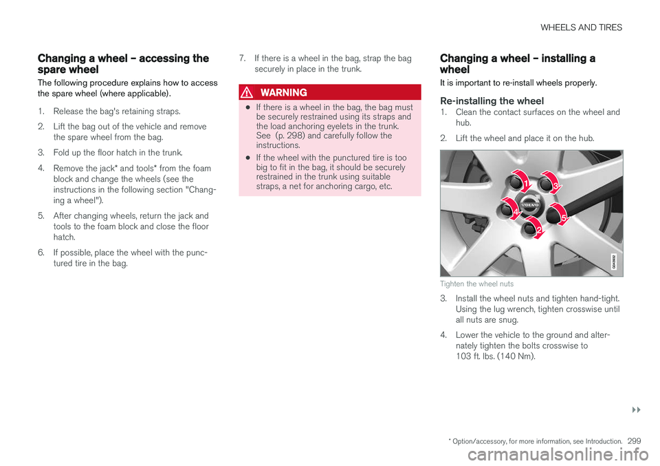
Re-installing the wheel1. Clean the contact surfaces on the wheel and hub.
2. Lift the wheel and place it on the hub.
Tighten the wheel nuts
3. Install the wheel nuts and tighten hand-tight. Using the lug wrench, tighten crosswise until all nuts are snug.
4. Lower the vehicle to the ground and alter- nately tighten the bolts crosswise to103 ft. lbs. (140 Nm).
Page 309 of 398

WHEELS AND TIRES
307
WARNING
The temperature grade for this tire is estab- lished for a tire that is properly inflated andnot overloaded. Excessive speed, under-infla-tion, or excessive loading, either separately orin combination, can cause heat buildup andtire failure.
Snow chains
Snow chains can be used on your Volvo with the following restrictions:
• Snow chains should be installed on front wheels only. Use only Volvo approved snowchains.
• If accessory, aftermarket or "custom" tiresand wheels are installed and are of a size dif-ferent than the original tires and wheels,chains in some cases CANNOT be used.Sufficient clearances between chains andbrakes, suspension and body componentsmust be maintained.
• Some strap-on type chains will interfere withbrake components and therefore CANNOTbe used.
• All Wheel Drive models
: Snow chains
should only be installed on the front wheels.
• Certain size tires may not allow the assemblyof snow chains/traction devices.
Consult your Volvo retailer for additional snowchain information.
CAUTION
• Check local regulations regarding the use of snow chains before installing.
• Use single-sided snow chains only.
• Always follow the chain manufacturer'sinstallation instructions carefully. Installchains as tightly as possible andretighten periodically.
• Never exceed the chain manufacturer'sspecified maximum speed limit. (Underno circumstances should you exceed31 mph (50 km/h).
• Avoid bumps, holes or sharp turns whendriving with snow chains.
• The handling of the vehicle can beadversely affected when driving withchains. Avoid fast or sharp turns as wellas locked wheel braking.
Page 331 of 398

MAINTENANCE AND SERVICING
329
retailer can access or search for this information using your vehicle's VIN number. This numbercan be found in your warranty booklet or on thedashboard at the lower left corner of the wind-shield.
–Select Maintenance & repairSend
vehicle data.
Booking information and vehicle dataWhen you opt to book service from your vehicle, booking information and vehicle data will betransmitted. Vehicle data consists of a number ofparameters in the following areas:
• Service requirements
• Function status
• Fluid levels
• Odometer reading (mileage)
• Vehicle Identification Number (VIN)
• The vehicle's software version
Related information
•
Volvo ID (p. 20)
Maintenance – opening/closing hood The hood is opened by first releasing the lock from the passenger compartment and thenpressing the release control.
Opening and closing the hood
Turn the handle located under the left side of the dash approximately 20-25 degreesclockwise to release the hood lock.
Lift the hood slightly. Press the release con- trol (located under the right front edge of thehood) to the left, and lift the hood.
WARNING
Check that the hood locks properly when closed.
Related information
•Maintenance – owner maintenance (p. 325)
• Engine compartment – overview (p. 330)
Page 339 of 398

MAINTENANCE AND SERVICING
}}
* Option/accessory, for more information, see Introduction.337
WARNING
•The engine should not be running when changing bulbs.
• If the engine has been running just priorto replacing bulbs in the headlight hous-ing, please keep in mind that componentsin the engine compartment will be hot.
WARNING
•
Active Bending Lights
* – due to the high
voltage used by these headlights, these bulbs should only be replaced by atrained and qualified Volvo service techni-cian.
• Turn off the lights and remove the remotekey from the ignition before changing anybulbs.
Related information
•Bulbs – headlight housing (p. 337)
• Bulbs – taillight housing (p. 342)
• Bulbs – vanity mirror lighting (p. 343)
• Bulbs – license plate lighting (p. 342)
Bulbs – headlight housing
The entire headlight housing must be lifted out when replacing all front bulbs.
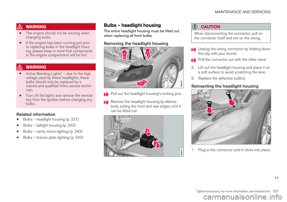
Removing the headlight housing
Pull out the headlight housing's locking pins.
Remove the headlight housing by alterna- tively pulling the front and rear edges until itcan be lifted out.
CAUTION
When disconnecting the connector, pull on the connector itself and not on the wiring.
Unplug the wiring connector by holding down the clip with your thumb.
Pull the connector out with the other hand.
5. Lift out the headlight housing and place it on a soft surface to avoid scratching the lens.
6. Replace the defective bulb(s).
Reinserting the headlight housing
1. Plug in the connector until it clicks into place.
Page 340 of 398

||
MAINTENANCE AND SERVICING
3382. Reinstall the headlight housing and locking
pins. The short locking pin should be closest to the grille. Check that they are correctlyinserted. The headlight housing must be properly in place and the wiring connector correctlyreconnected before the lighting is switchedon or the remote key is inserted into the igni-tion slot.
3. Check that the lights function properly.
Related information
• Bulbs – introduction (p. 336)
• Bulbs – cover (p. 338)
• Bulbs – specifications (p. 343)
Bulbs – cover The larger cover has to be removed in order to change the high/low beam headlight bulbs.
Removing the cover to access the
bulbs
NOTE
Before starting to replace a bulb, see Bulbs – introduction (p. 336).
1. Loosen the cover's four retaining screws (3-4 turns) with a Torx T20 tool (1). The screws should not be removed completely.
2. Push the cover to the side.
3. Remove the cover.Reinstall the cover in the reverse order.
Related information
• Bulbs – headlight housing (p. 337)
• Bulbs – low beam, Halogen (p. 339)
• Bulbs – high beam, Halogen (p. 339)
• Bulbs – extra high beam (p. 340)