Page 92 of 289
90StorageInstallation behind front seats
● There are installation openingson both sides in the roof frame
above the front seats: suspend
and engage rod of net at one
side, compress rod and suspend and engage at the other side.
● Attach hooks of safety net straps
to the lashing eyes on both sides in the floor in front of the seats.
● Tension both straps by pulling at the loose end.
Removal
Push button on the tightener to
release the strap on both sides.
Detach hooks from the eyes. Unhook
the safety net rods from the brackets in the roof frame. Roll up the net and
secure with a strap.
Stowing Open the cover of the storage in the
load compartment floor in front of the
tailgate.
Page 93 of 289
Storage91
Insert the safety net in the storage
and close cover.
Folding tray Located in the front seat backrests.
Open by pulling upwards until it
engages.
Fold away by pressing down past the resistance point.
Do not place any heavy objects on the
folding tray.
Warning triangle
Stow the warning triangle in the
storage of the load compartment floor
in front of the tailgate.
First aid kit Stow the first aid kit and the high
visibility vest under the driver's seat.
Use the straps to fix.
Page 95 of 289

Storage93Loading information
● Heavy objects in the loadcompartment should be placed
against the seat backrests.
Ensure the backrests are
securely engaged. If objects can
be stacked, the heavier objects should be placed at the bottom.
● Secure objects with lashing straps attached to lashing eyes
3 87.
● Secure loose objects in load compartment to prevent sliding.
● Do not allow the load to protrudeabove the upper edge of the
backrests.
● Do not place any objects on the load compartment cover or the
instrument panel.
● The load must not obstruct the operation of the pedals, parking
brake and gear selector lever, or
hinder the freedom of movement of the driver. Do not place any
unsecured objects in the interior.
● Do not drive with an open load compartment.9Warning
Always make sure that the load in
the vehicle is securely stowed.
Otherwise objects can be thrown
around inside the vehicle and
cause personal injury or damage
to the load or car.
● The payload is the difference between the permitted gross
vehicle weight (see identification
plate 3 261) and the EC kerb
weight.
To calculate the payload, enter
the data for your vehicle in the
weights table at the front of this
manual.
The EC kerb weight includes
weights for the driver (68 kg),
luggage (7 kg) and all fluids (fuel
tank 90% full).
Optional equipment and
accessories increase the kerb
weight.
● Driving with a roof load increases
the sensitivity of the vehicle to
cross-winds and has a
detrimental effect on vehicle
handling due to the vehicle's
higher centre of gravity.
Distribute the load evenly and secure it properly with retaining
straps. Adjust the tyre pressure
and vehicle speed according to
the load conditions. Check and
retighten the straps frequently.
Do not drive faster than 75 mph.
The permissible roof load is
75 kg for vehicles without roof
railing and 100 kg for vehicles
with roof railing. The roof load is
Page 104 of 289
102Instruments and controlsFurther 12 Volt power outlets are
located in the rear console
and at the left sidewall in the load
compartment.
Do not exceed the maximum power
consumption of 120 watts.
With ignition off, the power outlets are
deactivated. Additionally the power
outlets are deactivated in the event of
low vehicle battery voltage.
Electrical accessories that are
connected must comply with the
electromagnetic compatibility
requirements laid down in
DIN VDE 40 839.
Do not connect any current-delivering
accessories, e.g. electrical charging devices or batteries.
Do not damage the outlet by using
unsuitable plugs.
Stop-start system 3 153.
Cigarette lighter
The cigarette lighter is located in the
front console. Fold the cover
downwards.
Press in cigarette lighter. It switches off automatically once the element is
glowing. Pull out lighter.
AshtraysCaution
To be used only for ash and not for combustible rubbish.
The portable ashtray can be placed in
the cupholders.
Page 135 of 289

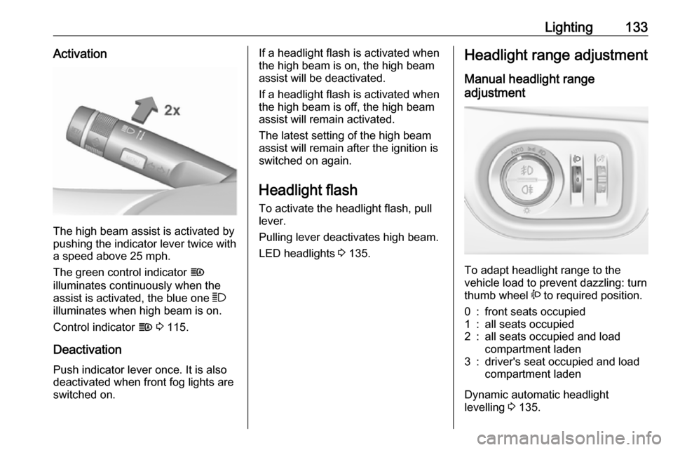
Lighting133Activation
The high beam assist is activated by
pushing the indicator lever twice with
a speed above 25 mph.
The green control indicator f
illuminates continuously when the
assist is activated, the blue one 7
illuminates when high beam is on.
Control indicator f 3 115.
Deactivation
Push indicator lever once. It is also
deactivated when front fog lights are
switched on.
If a headlight flash is activated when the high beam is on, the high beam
assist will be deactivated.
If a headlight flash is activated when
the high beam is off, the high beam
assist will remain activated.
The latest setting of the high beam
assist will remain after the ignition is
switched on again.
Headlight flash
To activate the headlight flash, pull
lever.
Pulling lever deactivates high beam.
LED headlights 3 135.Headlight range adjustment
Manual headlight range
adjustment
To adapt headlight range to the
vehicle load to prevent dazzling: turn
thumb wheel ? to required position.
0:front seats occupied1:all seats occupied2:all seats occupied and load
compartment laden3:driver's seat occupied and load
compartment laden
Dynamic automatic headlight
levelling 3 135.
Page 158 of 289

156Driving and operatingNotice
In the event of an accident with
airbag deployment, the engine is
turned off automatically if the vehicle
comes to a standstill within a certain time.Engine exhaust9 Danger
Engine exhaust gases contain
poisonous carbon monoxide,
which is colourless and odourless and could be fatal if inhaled.
If exhaust gases enter the interior
of the vehicle, open the windows.
Have the cause of the fault
rectified by a workshop.
Avoid driving with an open load
compartment, otherwise exhaust
gases could enter the vehicle.
Diesel particle filter
Automatic cleaning process
The diesel particle filter system filters
harmful soot particles out of the
exhaust gases. The system includes
a self-cleaning function that runs
automatically during driving without
any notification. The filter is cleaned
by periodically burning off the soot
particles at high temperature. This
process takes place automatically
under set driving conditions and may take up to 25 minutes. Typically it
needs between seven and twelve
minutes. Autostop is not available
and fuel consumption may be higher
during this period. The emission of
smells and smoke during this process is normal.
System requires manual cleaning
process
Under certain driving conditions, e.g.
short distances, the system cannot
clean itself automatically.
If cleaning of the filter is required and
if previous driving conditions did not
enable automatic cleaning, it will be
Page 205 of 289

Driving and operating203The misfuel inhibitor ensures that the
flap of the fuel filler neck can only be
opened by using a nozzle for diesel
fuel or a funnel for emergency
refilling.
Turn the fuel filler cap slowly
anticlockwise.
The cap can be retained in the
bracket on the fuel filler flap.
Place the nozzle in a straight line to the filler neck and press with slight
force to insert.
In case of an emergency, refill with a
canister. A funnel must be used to
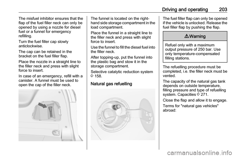
open the cap of the filler neck.The funnel is located on the right-
hand side storage compartment in the load compartment.
Place the funnel in a straight line to
the filler neck and press with slight force to insert.
Use the funnel to fill the diesel fuel into
the filler neck.
After topping-up, put the funnel into
the plastic bag and stow it in the storage compartment.
Selective catalytic reduction system
3 158.
Natural gas refuellingThe fuel filler flap can only be opened
if the vehicle is unlocked. Release the
fuel filler flap by pushing the flap.9 Warning
Refuel only with a maximum
output pressure of 250 bar. Use
only temperature-compensated
filling stations.
The refuelling procedure must be
completed, i.e. the filler neck must be
vented.
The capacity of the natural gas tank depends on outside temperature,
filling pressure and type of refuelling
system. Capacities 3 271.
Close the flap and allow it to engage. Terms for "natural gas vehicles"
abroad:
Page 211 of 289
Driving and operating209Stowage of coupling ball bar
The bag with the coupling ball bar is
stowed in the load compartment.
Place the strap through the right rear lashing eye, wrap around twice and
tighten the strap to secure the bag.
Fitting the coupling ball bar
Disengage and fold down the socket. Remove the sealing plug from the
opening for the coupling ball bar and
stow it.
Checking the tensioning of the
coupling ball bar
● Red marking on rotary knob must
point towards green marking on
coupling ball bar.
● The gap between the rotary knob
and the coupling ball bar must be approx. 6 mm.
● The key must be in position c.
Otherwise, the coupling ball bar must be tensioned before being inserted:
● Unlock coupling ball bar by turning key to position c.