Page 69 of 464

691-1. For safe use
1
For safety and security
MIRAI_OM_USA_OM62023U
After installing the child restraint system, rock it back and forth to
ensure that it is installed securely.
■Laws and regulations pertaining to anchors
The LATCH system conforms to FMVSS225 or CMVSS210.2.
Child restraint systems conforming to FMVSS213 or CMVSS213 specifica-
tions can be used.
This vehicle is designed to conform to SAE J1819.
■
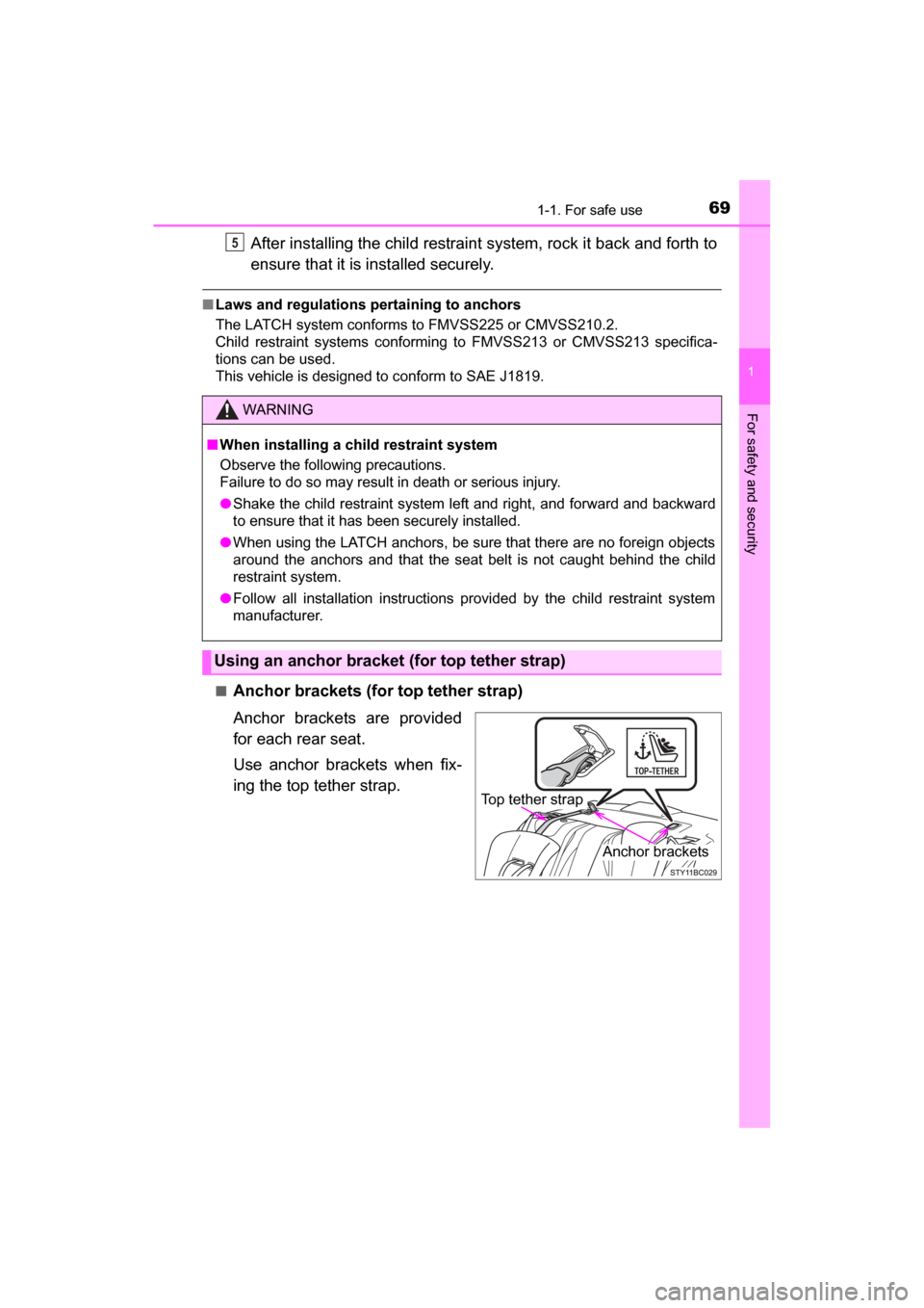
Anchor brackets (for top tether strap)
Anchor brackets are provided
for each rear seat.
Use anchor brackets when fix-
ing the top tether strap.
WARNING
■ When installing a child restraint system
Observe the following precautions.
Failure to do so may result in death or serious injury.
● Shake the child restraint system left and right, and forward and backward
to ensure that it has been securely installed.
● When using the LATCH anchors, be sure that there are no foreign objects
around the anchors and that the seat belt is not caught behind the child
restraint system.
● Follow all installation instructions provided by the child restraint system
manufacturer.
Using an anchor bracket (for top tether strap)
5
Top tether strap
Anchor brackets
Page 71 of 464
711-1. For safe use
1
For safety and security
MIRAI_OM_USA_OM62023U
WARNING
■When installing a child restraint system
Observe the following precautions.
Failure to do so may result in death or serious injury.
● Firmly attach the top tether strap and make sure that the belt is not twisted.
● Do not attach the top tether strap to anything other than the anchor
bracket.
● Shake the child restraint system left and right, and forward and backward
to ensure that it has been securely installed.
● Follow all installation instructions provided by the child restraint system
manufacturer.
● When installing the child restraint system with the head restraint being
raised, after the head restraint has been raised and then the anchor
bracket has been fixed, do not lower the head restraint.
NOTICE
■ Anchor brackets (for top tether strap)
When not in use, make certain to close the lid. If it remains open, the lid
may be damaged.
Page 73 of 464

731-2. Theft deterrent system
1
For safety and security
MIRAI_OM_USA_OM62023U
■System maintenance
The vehicle has a maintenance-free type immobilizer system.
■ Conditions that may cause the system to malfunction
●If the grip portion of the key is in contact with a metallic object
● If the key is in close proximity to or touching a key registered to the security
system (key with a built-in transponder chip) of another vehicle
■ Certification for the immobilizer system
FCC ID: NI4TMIMB-3
This device complies with part 15 of the FCC Rules. Operation is subject to
the following two conditions: (1) This device may not cause harmful interfer-
ence, and (2) this device must accept any interference received, including
interference that may cause undesired operation.
Changes or modifications not expressly approved by the party responsible for
compliance could void the user’s authority to operate the equipment.
WARNING
■ Certifications for the immobilizer system
Changes or modifications not expressly approved by the party responsible
for compliance could void the user’s authority to operate the equipment.
NOTICE
■To ensure the system operates correctly
Do not modify or remove the system. If modified or removed, the proper
operation of the system cannot be guaranteed.
Page 82 of 464
822. Fuel cell vehicle
MIRAI_OM_USA_OM62023U
Fuel cell vehicle precautions
The fuel cell vehicle has hydrogen tanks (10150 psi [70 MPa,
714 kgf/cm2, 700 bar]), fuel cell stack, and hydrogen pipelines as
hydrogen-related components. Pay attention to all warning labels
attached to the vehicle.
This diagram is for illust rative purposes only and may differ from the
actual vehicle.
Hydrogen-related components
Warning label
Hydrogen detectors
Fuel cell stack Hydrogen tanks
Hydrogen tank valves
Hydrogen pipelines
Page 83 of 464
832. Fuel cell vehicle
2
Fuel cell system
MIRAI_OM_USA_OM62023U
The fuel cell vehicle has high-voltage components (about 650 V maxi-
mum) such as a fuel cell stack, traction battery, power control unit,
high-voltage cables (which are distinguished from low-voltage cables
by their orange covers), electric motor (traction motor), etc., and high-
temperature parts such as the radiator for cooling. Pay attention to all
warning labels attached to the vehicle.
This diagram is for illust rative purposes only and may differ from the
actual vehicle.
High-voltage and high-temperature components
Warning label
Power control unit
High-voltage cables (orange)
Fuel cell stack
Traction battery
Service plug
Fuel cell converter Electric motor (traction motor)
Air conditioning compressor
Radiator for inverter cooling
Radiator for fuel cell stack
cooling
Auxiliary inverter
Cabin coolant heater
Page 84 of 464

842. Fuel cell vehicle
MIRAI_OM_USA_OM62023U
When a certain level of impact from an accident is detected, the fuel
cell system is shut down and the system shuts out the high voltage.
Also, the fuel supply is stopped from the hydrogen tank valves. If the
emergency shut off system activates, your vehicle will not restart. To
restart the fuel cell system, contact your Toyota dealer.
A message is automatically displa yed when a malfunction occurs in
the fuel cell system or an im proper operation is attempted.
If a warning message is shown on
the multi-information display, read
the message and follow the
instructions. ( →P. 376)
Fuel cell vehicles do not have engi ne sounds like gasoline vehicles.
Therefore, it makes an artificial no ise at low speeds to notify pedestri-
ans and nearby vehicles that it is approaching. The sound varies with
speed and will stop when the v ehicle exceeds approximately 15 mph
(25 km/h).
Emergency shut off system
Fuel cell warning message
Vehicle proximity notification system
Page 85 of 464

852. Fuel cell vehicle
2
Fuel cell system
MIRAI_OM_USA_OM62023U
There is an air intake vent beside
the rear left seat for the purpose
of cooling the traction battery. If
the air intake vent is blocked, it
could lead to a reduction in trac-
tion battery output.
■ If a warning light comes on, a warn ing message is displayed, or the 12-
volt battery connection is disconnected
The fuel cell system may not be able to restart.
If the “READY” indicator does not come on, even when the start pro\
cedure is
repeated, contact your Toyota dealer.
■ If “Hydrogen Leakage Detected Visit Your Dealer” is displayed on the
multi-information display
A small amount of hydrogen gas may be leaking. Have the vehicle inspected
immediately at the nearest Toyota dealer.
■ If “FC System Shutdown due to Hydrogen Leakage Stop Your Vehicle in
a Safe Place and Contact Your Dealer ” is displayed on the multi-informa-
tion display
● Hydrogen gas may be leaking.
When hydrogen gas is leaking or some other malfunction is detected:
→P. 9 0
● The air conditioning system will shut off automatically.
■ Running out of fuel
When the vehicle has run out of fuel and the fuel cell system cannot be
started, refuel the vehicle until the low fuel level warning light ( →P. 371) turns
off before trying to restart. It may not be able to restart if the refueled amount
is too low (less than about 2.7 lb. [1.2 kg]).
Traction battery air intake vent
Page 88 of 464

882. Fuel cell vehicle
MIRAI_OM_USA_OM62023U■
Power output restriction
When the power output is restricted, the vehicle may fail to accelerate or even
decelerate, even though the accelerator pedal is depressed. If a safe driving
speed cannot be maintained, stop the vehicle in a safe place away from the
traffic. This may be caused by the following conditions:
●The coolant temperature may be too high. This can be caused by driving
conditions such as repeated sudden acceleration and deceleration, continu-
ous driving on an incline, continuous driving at high altitudes with a high
load, etc. In such situations, the power output restriction indicator (amber) is
displayed on the main display, “High FC Temperature Reduced Power” is
displayed on the multi-information display, and the power output is
restricted. Once the coolant returns to normal temperature, the power out-
put will return to normal. ( →P. 377)
● The remaining fuel may be low. After the low fuel warning indicator comes
on, the output power will be gradually restricted in order to extend the possi-
ble driving distance. Once getting to this point, the remaining driving dis-
tance possible is short. Immediately refill the vehicle with hydrogen.
● On cold days, the low fuel warning indicator comes on faster than usual and
the output power is restricted.
■ Vehicle proximity notification system
In the following cases, the vehicle proximity notification system may be diffi-
cult to hear for people around.
●In very noisy areas
● In wind or rain
Also, because the vehicle proximity notification system is located in the front
of the vehicle, it may be more difficult to hear from the rear of the vehicle
compared to the front.
■ Electromagnetic waves (EMF)
●High-voltage parts and cables in fuel cell vehicles have an electromagne\
tic
shielding configuration, and therefore emit approximately the same amount
of electromagnetic waves as conventional gasoline-powered vehicles or
home electronic appliances.
● Your vehicle may cause sound interference in some third party-produced
radio parts.
■ Traction battery
The traction battery has a limited service life. The lifespan of the traction bat-
tery can change according to driving style and driving conditions.