Page 222 of 505
222
2-2. Instrument cluster
86_EE (OM18071E)
Scale of the G-force display
The scale of the record of the
maximum G-forces and G-force
ball trace can be changed
between 1.0 G and 0.5 G by
pressing and holding while
the normal display screen is dis-
played.
Accelerator pedal input
Brake fluid pressure
Steering amount
If the steering wheel is turned
completely to the left or right, the
bottom side of the gauge on the
corresponding side will be illumi-
nated in red.
This display is intended for use as a guideline. Depending on factors such as
the road surface condition, temperature and vehicle speed, the display may
not show the actual condition of the vehicle.
■ Power and torque curve
Power output
Torque
Current engine speed
The vertical bar will slide laterally
according to the current engine
speed.
This chart is intended for reference only and does not show the actual
engine torque or output.
Page 447 of 505

5
447
5-2. Steps to take in an emergency
When trouble arises
86_EE (OM18071E)
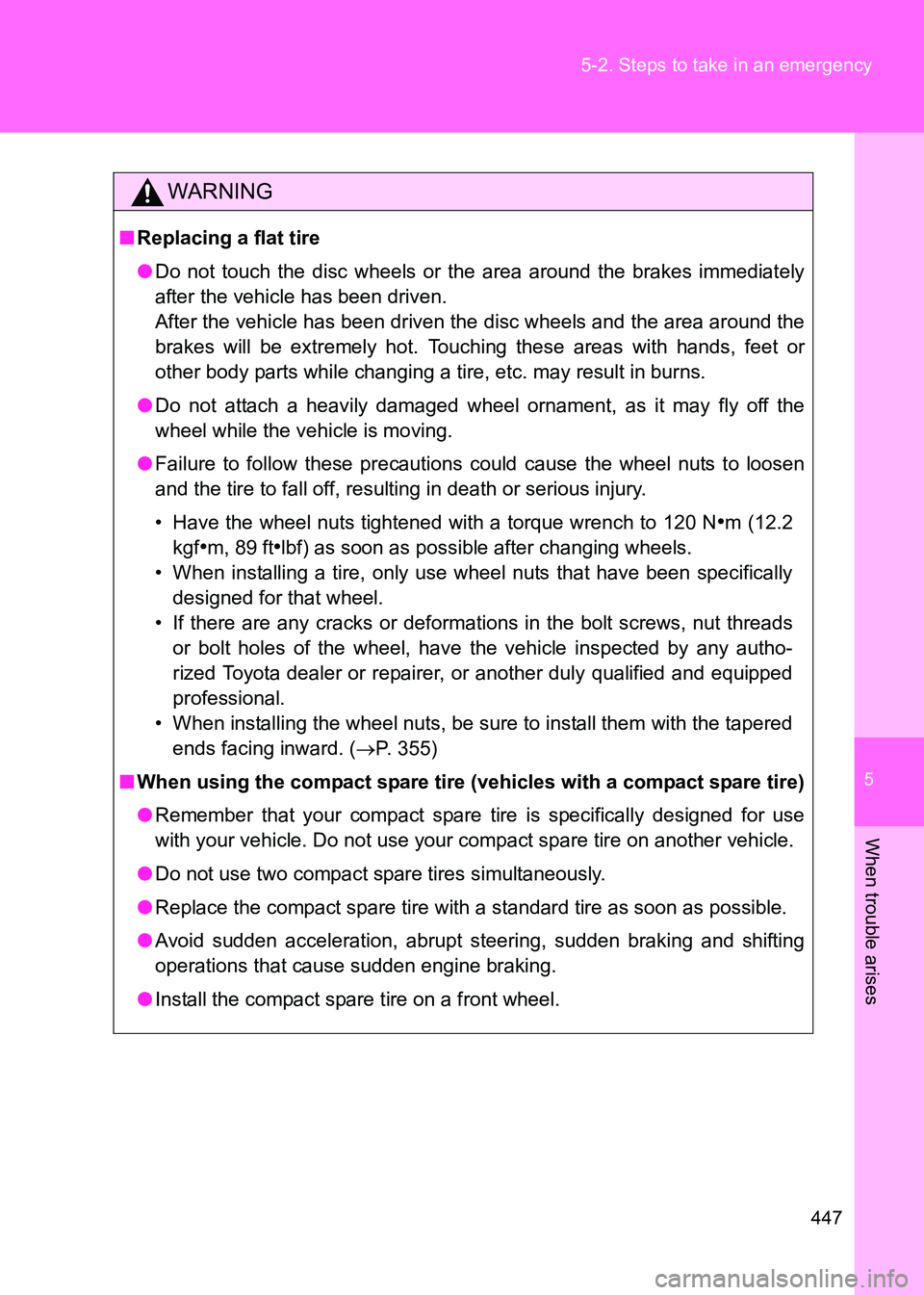
WARNING
■
Replacing a flat tire
●Do not touch the disc wheels or the area around the brakes immediately
after the vehicle has been driven.
After the vehicle has been driven the disc wheels and the area around the
brakes will be extremely hot. Touching these areas with hands, feet or
other body parts while changing a tire, etc. may result in burns.
● Do not attach a heavily damaged wheel ornament, as it may fly off the
wheel while the vehicle is moving.
● Failure to follow these precautions could cause the wheel nuts to loosen
and the tire to fall off, resulting in death or serious injury.
• Have the wheel nuts tightened with a torque wrench to 120 N
•m (12.2
kgf
•m, 89 ft•lbf) as soon as possible after changing wheels.
• When installing a tire, only use wheel nuts that have been specifically designed for that wheel.
• If there are any cracks or deformations in the bolt screws, nut threads or bolt holes of the wheel, have the vehicle inspected by any autho-
rized Toyota dealer or repairer, or another duly qualified and equipped
professional.
• When installing the wheel nuts, be sure to install them with the tapered ends facing inward. ( →P. 355)
■ When using the compact spare tire (vehicles with a compact spare tire)
●Remember that your compact spare tire is specifically designed for use
with your vehicle. Do not use your compact spare tire on another vehicle.
● Do not use two compact spare tires simultaneously.
● Replace the compact spare tire with a standard tire as soon as possible.
● Avoid sudden acceleration, abrupt steering, sudden braking and shifting
operations that cause sudden engine braking.
● Install the compact spare tire on a front wheel.
Page 483 of 505
483
6-1. Specifications
6
Vehicle specifications
86_EE (OM18071E)
Brakes
*1: Minimum pedal clearance when depressed with a force of 490 N (50 kgf,
110 lbf) while the engine is running.
*2: Parking brake lever travel when pulled up with a force of 200 N (20.4 kgf,45.0 lbf).
Steering
Tires and wheels
Pedal clearance*155.0 mm (2.16 in.) min.
Pedal free play 0.5 2.7 mm (0.020 0.106 in.)
Parking brake lever travel*27 8 clicks
Fluid type SAE J1703 or FMVSS No.116 DOT 3 or
SAE J1704 or FMVSS No.116 DOT 4
Free play Less than 30 mm (1.2 in.)
Tire size205/55R16 91V, 215/45R17 87W,
T135/80D16 101M
Tire inflation pressure
(Recommended cold tire
inflation pressure)240 kPa (2.4 kgf/cm2 or bar, 35 psi)
Tire inflation pressure
(compact spare)
(Recommended cold tire
inflation pressure)420 kPa (4.2 kgf/cm
2 or bar, 60 psi)
Wheel size
16
× 6 1/2 J, 17 × 7 J, 16 × 4T (compact
spare)
Wheel nut torque 120 N•m (12.2 kgf•m, 89 ft•lbf)