2017 SUBARU LEGACY shift lever
[x] Cancel search: shift leverPage 21 of 610

MT models1) Shift lever (page 7-23)
2) Climate control (page 4-1)
3) Audio (page 5-1)/Navigation system (Re-
fer to the Owner ’s Manual supplement for
the navigation system)
4) Glove box (page 6-6)
5) Accessory power outlet (page 6-10)
6) Cup holder (page 6-8)
7) Electronic parking brake switch (page 7-43)
8) Hill Holder switch (page 7-46)
16
Page 24 of 610

&Steering wheel1) Audio control switches (page 5-63)
2) Talk switch for voice command system
(page 5-81)
3) Cruise control (page 7-50)
4) Shift paddle (page 7-29)
5) Tilt/telescopic lock lever (page 3-82)
6) Hands-free phone switches (page 5-73)
7) Multi information display control switches (page 3-36)
8) SRS airbag (page 1-41)
9) Horn (page 3-83)
10) Heated steering wheel switch (page 3-83)
–CONTINUED –
19
Page 162 of 610

&Switching power status
1) Operation indicator
2) Push-button ignition switch
The power status is switched every time
the push-button ignition switch is pressed.
1. Carry the access key, and sit in the
driver ’s seat.
2. Shift the select lever into the “P ”
position.
3. Press the push-button ignition switch
without depressing the brake pedal. Every
time the button is pressed, the power is
switched in the sequence of “OFF ”,
“ACC ”,“ON ”and “OFF ”. When the engine
is stopped and the push-button ignition
switch is in “ACC”or “ON ”, the operation
indicator on the push-button ignition
switch illuminates in orange.
Power status Indicator color Operation
OFF Turned off Power is turned
off.
ACC Orange The following
systems can be used:
audio and ac-
cessory power
outlet.
ON Orange
(while engine is stopped) All electrical
systems can be
used.
Turned off
(while engine is
running)
CAUTION
.To prevent the vehicle battery
from discharging, do not leave
the push-button ignition switch
in the “ON ”or “ACC ”position for
a long time.
. To avoid a malfunction, observe
the following precautions.
– Do not spill drinks or other
liquids on the push-button
ignition switch.
– Do not touch the push-button
ignition switch with a hand
that is soiled with oil or other contaminants.
. If the push-button ignition switch
does not operate smoothly, stop
the operation. Contact a
SUBARU dealer immediately.
. If the push-button ignition switch
does not illuminate even when
the instrument panel illumination
is turned on, have the vehicle
inspected at a SUBARU dealer.
. If the vehicle was left in the hot
sun for a long time, the surface of
the push-button ignition switch
may get hot. Be careful not to
burn yourself.
NOTE
. When operating the push-button
ignition switch, firmly press it all the
way.
. If the push-button ignition switch is
pressed quickly, the power may not
turn on or off.
. If the indicator light on the push-
button ignition switch flashes in green
when the push-button ignition switch is
pressed, steering is locked. When this
occurs, press the push-button ignition
switch while turning the steering wheel
left and right.
Instruments and controls/Push –button ignition switch (models with push –button start system)
–CONTINUED –3-7
Page 166 of 610

to protect the engine from overrev-
ving. The engine will resume run-
ning normally after the engine speed
is reduced below the red zone.
NOTE
To protect the engine while the select
lever is in the“P ” or “N ” position (for
CVT models) or the shift lever is in the
neutral position (for MT models), the
engine is controlled so that the engine
speed may not become too high even if
the accelerator pedal is pressed hard.
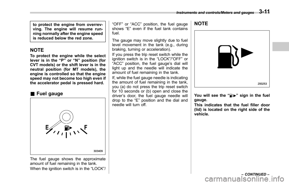
& Fuel gauge
The fuel gauge shows the approximate
amount of fuel remaining in the tank.
When the ignition switch is in the “LOCK”/ “OFF
”or “ACC ”position, the fuel gauge
shows “E”even if the fuel tank contains
fuel.
The gauge may move slightly due to fuel
level movement in the tank (e.g., during
braking, turning or acceleration).
If you press the trip reset switch while the
ignition switch is in the “LOCK”/“OFF ”or
“ACC ”position, the fuel gauge ’s dial will
light up and the needle will indicate the
amount of fuel remaining in the tank.
If, while the fuel gauge needle is indicating
the amount of fuel remaining in the tank,
you (a) do not press the trip reset switch
for 10 seconds or (b) open and close the
driver ’s door, the fuel gauge needle will
drop to the “E”position and the dial and
needle will turn off.
NOTE
You will see the “”sign in the fuel
gauge.
This indicates that the fuel filler door
(lid) is located on the right side of the
vehicle.
Instruments and controls/Meters and gauges
–CONTINUED –3-11
Page 183 of 610

Instruments and controls/Warning and indicator lights
Inside warningchime Outside warning
chime Operation indicator
on push-button
ignition switch Status Action
Ding —— Access key warning for engine start:
The push-button ignition switch is pressed
while the access key is not inside the
vehicle. Carry the access key, and press the push-
button ignition switch.
Ding Beep, beep,
beep (3 times) —Access key takeout warning:
The driver exits the vehicle with the access
key and closes the driver
’s door while the
push-button ignition switch is in a position
other than “OFF ”and the select lever is in
the “P ”position. Switch the push-button ignition switch to
“
OFF” , and get out of the vehicle.
Ding Beep, beep,
beep (3 times) —Passenger access key takeout warning:
A fellow passenger exits the vehicle with the
access key and closes a door other than the
driver
’s door while the push-button ignition
switch is in a position other than “OFF ”. Return the access key to inside the vehicle,
or switch the push-button ignition switch to
“
OFF” .
Long beep
(continuous) Long beep
(continuous) —Access key takeout without
“P ” position
warning:
The driver exits the vehicle with the access
key and closes the driver ’s door while the
push-button ignition switch is in a position
other than “OFF ”and the select lever is in a
position other than the “P ”position. Shift the select lever to the
“P ”position,
switch the push-button ignition switch to
“ OFF” and exit the vehicle.
Long beep
(continuous) —— Select lever position warning:
.
Case
1: The engine is turned off by
pressing the push-button ignition switch
while the select lever is in a position
other than the “P ”position.
. Case 2: The driver ’s door is opened
while the push-button ignition switch is in
a position other than “OFF ”and the
select lever is in a position other than the
“ P ”position. .
Case 1: Start the engine, shift the
select lever to the “P ”position, switch the
push-button ignition switch to “OFF ”and
exit the vehicle.
. Case 2: Shift the select lever to the
“ P ”position, switch the push-button
ignition switch to “OFF ”and exit the
vehicle.
3-28
Page 186 of 610

&Select lever/gear position in-
dicator
1) Upshift indicator
2) Downshift indicator
3) Select lever/gear position indicator
For CVT models, the select lever position
is displayed on the indicator.
For MT models, the current gear selection
is displayed on the indicator.
! Upshift/downshift indicator (CVT
models)
When the manual mode is selected, the
gear position indicator (which shows the
current gear selection) and the upshift/
downshift indicator light up. Refer to
“Selection of manual mode ”F 7-29. !
Gear position indicator setting (MT
models)
The gear position indicator light can be
activated or deactivated. For details about
the setting procedure, refer to “Gear
Position Indicator Settings (MT models) ”
F 3-44.
&Turn signal indicator
lights
These lights show the operation of the turn
signal or lane change signal.
If the indicator lights do not blink or blink
rapidly, the turn signal bulb may be burned
out. Replace the bulb as soon as possible.
Refer to “Replacing bulbs ”F 11-40.
&High beam indicator
light
This light shows that the headlights are in
the high beam mode.
This indicator light also illuminates when
operating the headlight flasher.
&High beam assist indi-
cator (green) (if
equipped)
This indicator appears when the high
beam assist function is activated. For
details about the high beam assist func- tion, refer to
“High beam assist function ”
F 3-49.
&High beam assist
warning indicator
(yellow) (if equipped)
This warning indicator appears when the
high beam assist function malfunctions.
When this warning indicator appears,
have your vehicle inspected by your
SUBARU dealer.
&Cruise control indica-
tor
This indicator appears when the cruise
control main button is pressed to activate
the cruise control function. For details,
refer to “To set cruise control ”F 7-50.
CAUTION
If the CHECK ENGINE warning light/
malfunction indicator light illumi-
nates, the cruise control indicator
flashes at the same time. At this
time, do not drive at high speed and
have your vehicle inspected at a
SUBARU dealer as soon as possi-
ble.
Instruments and controls/Warning and indicator lights
–CONTINUED –3-31
Page 215 of 610

Instruments and controls/Wiper and washer
Windshield washer fluid warning indicator
NOTE
The windshield washer fluid warning
indicator appears when the washer
fluid level in the tank has dropped to
the lower limit. If the warning indicator
appears, refill the tank with fluid. For
the tank refilling method, refer to
“Windshield washer fluid ”F 11-32.
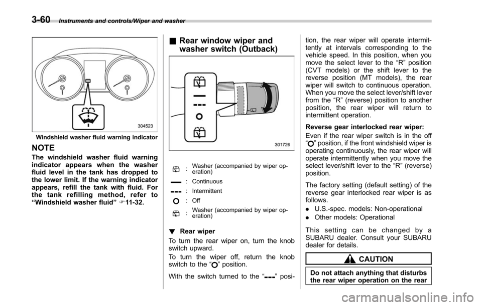
& Rear window wiper and
washer switch (Outback)
:Washer (accompanied by wiper op-
eration)
: Continuous
: Intermittent
: Off
:Washer (accompanied by wiper op-
eration)
!
Rear wiper
To turn the rear wiper on, turn the knob
switch upward.
To turn the wiper off, return the knob
switch to the “
”position.
With the switch turned to the “
”posi- tion, the rear wiper will operate intermit-
tently at intervals corresponding to the
vehicle speed. In this position, when you
move the select lever to the
“R”position
(CVT models) or the shift lever to the
reverse position (MT models), the rear
wiper will switch to continuous operation.
When you move the select lever/shift lever
from the “R”(reverse) position to another
position, the rear wiper will return to
intermittent operation.
Reverse gear interlocked rear wiper:
Even if the rear wiper switch is in the off
“
” position, if the front windshield wiper is
operating continuously, the rear wiper will
operate intermittently when you move the
select lever/shift lever to the “R”(reverse)
position.
The factory setting (default setting) of the
reverse gear interlocked rear wiper is as
follows.
. U.S.-spec. models: Non-operational
. Other models: Operational
This setting can be changed by a
SUBARU dealer. Consult your SUBARU
dealer for details.
CAUTION
Do not attach anything that disturbs
the rear wiper operation on the rear
3-60
Page 224 of 610

1) HomeLink®button 1
2) HomeLink®button 2
3) HomeLink®button 3
1. Press and hold the two outer buttons
(button 1 and button 3) until the indicator
light begins to flash (after approximately
20 seconds).
2. Release both buttons.
!In case a problem occurs
If you cannot activate a device using the
corresponding HomeLink
®button after
programming, contact HomeLink®at
www.homelink.com or call 1-800-355-
3515 for assistance.
& Auto-dimming mirror with
HomeLink
®(except U.S.-
spec. models - if equipped)
1) HomeLink®button 1
2) HomeLink®button 2
3) LED
4) HomeLink
®button 3
5) Sensor
6) Automatic dimming on button
7) Automatic dimming off button
The auto-dimming mirror has an anti-glare
feature which automatically reduces glare
coming from headlights of vehicles behind
you. It also contains a HomeLink
®wireless
control system.
By pressing the automatic dimming on/off
button, the automatic dimming function is
turned on or off. When the automatic dimming function is on, the LED indicator
will illuminate.
Even with the mirror in the automatic
dimming mode, the mirror surface turns
bright if the shift lever/select lever is
shifted into the
“R ”(reverse) position. This
is to ensure good rearward visibility during
reversing.
When cleaning the mirror, use a paper
towel or similar material dampened with
glass cleaner. Do not spray glass cleaner
directly on the mirror as that may cause
the liquid cleaner to enter the mirror
housing and damage the mirror.
! Photosensors
The mirror has a photosensor attached on
both the front and back sides. During
nighttime driving, these sensors detect
Instruments and controls/Mirrors
–CONTINUED –3-69