2017 SUBARU LEGACY warning lights
[x] Cancel search: warning lightsPage 406 of 610

If the brake system warning light and ABS
warning light illuminate simultaneously,
take the following steps.
1. Stop the vehicle in the nearest safe,
flat location.
2. Apply the parking brake and turn off
the engine.
3. Restart the engine.
4. Release the parking brake.
Even if both warning lights turn off:
The EBD system may be malfunctioning.
Drive carefully to the nearest SUBARU
dealer and have the system inspected.
If both warning lights illuminate again
and remain illuminated after restarting
the engine:
1. Turn off the engine again.
2. Apply the parking brake.
3. Check the brake fluid level. For details
about checking the brake fluid level, refer
to“Checking the fluid level ”F 11-20.
. If the brake fluid level is not below the
“MIN ”mark, the EBD system may be
malfunctioning. Drive carefully to the
nearest SUBARU dealer and have the
system inspected.
. If the brake fluid level is below the
“MIN ”mark, DO NOT drive the vehicle.
Instead, have the vehicle towed to the nearest SUBARU dealer for repair.
WARNING
.
Driving with the brake system
warning light on is dangerous.
This indicates your brake system
may not be working properly. If
the light remains on, have the
brakes inspected by a SUBARU
dealer immediately.
. If at all in doubt about whether
the brakes are operating prop-
erly, do not drive the vehicle.
Have your vehicle towed to the
nearest SUBARU dealer for re-
pair.
Vehicle Dynamics Control
system
WARNING
Always use the utmost care in
driving –overconfidence because
you are driving with a Vehicle Dy-
namics Control system equipped
vehicle could easily lead to a ser-
ious accident.
CAUTION
. Even if your vehicle is equipped
with Vehicle Dynamics Control
system, winter tires should be
used when driving on snow-cov-
ered or icy roads; in addition,
vehicle speed should be reduced
considerably. Simply having a
Vehicle Dynamics Control sys-
tem does not guarantee that the
vehicle will be able to avoid
accidents in any situation.
. Activation of the Vehicle Dy-
namics Control system is an
indication that the road being
travelled on has a slippery sur-
face; since having Vehicle Dy-
Starting and operating/Vehicle Dynamics Control system
–CONTINUED –7-35
Page 415 of 610

Starting and operating/Parking your vehicle
position (CVT models). When
the select lever cannot be
shifted into the“P ” position,
you must release shift lock.
Refer to “Shift lock function ”
F 7-28.
– Use tire stops under the tires
to prevent the vehicle from
moving.
. Never drive with the parking
brake applied in order to avoid
unnecessary wear on the brake
linings. Before starting to drive,
always make sure that the park-
ing brake has been released and
that the electronic parking brake
indicator light has turned off.
. The braking power of the electro-
nic parking brake may not be
sufficient when strong braking
power is needed (e.g., when
parking on a steep slope while
towing a trailer (Outback)).
Your vehicle is equipped with an electronic
parking brake. You can apply/release the
parking brake by operating the parking
brake switch.
To apply: Depress the brake pedal and
pull up the parking brake switch.
To release: Press the parking brake switch firmly while the ignition switch is
in the
“ON”position and the brake pedal is
depressed.
Electronic parking brake indicator light
When the parking brake is applied while
the ignition switch is in the “ON”position,
the following indicator lights illuminate.
. the indicator light on the parking brake
switch
. the electronic parking brake indicator
light on the combination meter (for details,
refer to “Electronic parking brake indicator
light ”F 3-21.)
NOTE
. The parking brake will not be re-
leased under the following conditions
even if the parking brake switch is
pressed. –
Theignitionswitchisinthe
“ ACC ”or “LOCK ”/“ OFF ”position.
– The brake pedal (all models) and/
or clutch pedal (MT models) are not
depressed.
. The electronic parking brake system
uses motors to apply the parking
brake. Therefore, operating sounds
from the motors will be heard when
applying or releasing the parking
brake. Make sure that the motor
sounds are heard when applying or
releasing the parking brake.
. When the electronic parking brake
system has a malfunction or the elec-
tronic parking brake operation is pro-
hibited temporarily, if the parking brake
switch is operated, a chirp sound is
heard and the electronic parking brake
indicator light flashes.
. When you cannot release the park-
ing brake due to, for example, a system
malfunction, contact your SUBARU
dealer and have your SUBARU dealer
release the parking brake.
. If the operation of the electronic
parking brake switch is stopped mid-
way or performed extremely slowly, the
system may detect an error and turn on
the brake system warning light. How-
ever, this does not indicate a malfunc-
tion if the warning light turns off after
7-44
Page 429 of 610

Starting and operating/BSD/RCTA
tected.
The indicator light will
flash to warn the
driver of dangers under the following
conditions.
. While the indicator light is illuminating,
if the turn signal lever is operated toward
the side in which this light turned on
. When reversing the vehicle while the
system detects a vehicle approaching
from either side
! BSD/RCTA approach indicator
light dimming function
When the headlights are turned on, the
brightness of the BSD/RCTA approach
indicator light will be reduced.
NOTE
. You may have difficulty seeing the
BSD/RCTA approach indicator light
under the following conditions.
–When sunlight shines directly on
it
– When the headlight beams from a
vehicle traveling behind shines di-
rectly on it
. While the illumination brightness
control dial is in the fully upward
position, even if the headlights are
turned on, the brightness of the BSD/
RCTA approach indicator light will not
be reduced. For details about the illumination brightness control dial,
refer to
“Illumination brightness con-
trol” F3-55.
! BSD/RCTA approach warning buz-
zer (only when reversing)
A warning buzzer sounds along with
flashing of the BSD/RCTA approach in-
dicator light to warn the driver of dangers.
The setting of the warning buzzer volume
can be changed by operating the multi
information display of the combination
meter. For details, refer to “BSD/RCTA”
F 3-45.
! Safety tips regarding the BSD/RCTA
approach indicator light/warning
buzzer
. In the following cases, operation of the
BSD/RCTA approach indicator light and
the warning buzzer may be delayed or the
system may fail to issue these warnings.
–Whenavehiclemovestothe
neighboring lane from a lane next to
the neighboring lane
– When driving on a steep incline or
on repeated sharp uphill and downhill
grades
– When going beyond a pass
– When both your vehicle and a
vehicle driving on a neighboring lane
are driving on the far side of each lane. –
When several narrowly-spaced ve-
hicles are approaching in a row
– In low radius bends (tight bends or
when making turns at an intersection)
– When there is a difference in height
between your lane and the neighbor-
ing lane
– Immediately after the BSD/RCTA is
activated by pressing the BSD/RCTA
OFF switch
– Immediately after the shift lever/
select lever is shifted to the “R ”
position
– When extremely heavy cargo is
loaded in the trunk or cargo area
. During reversing, operation of the BSD/
RCTA approach indicator light and the
warning buzzer may be delayed or the
system may fail to issue these warnings
under the following conditions.
–When backing out of an angled
parking space
– When a large-sized vehicle is
parked next to your vehicle (That
vehicle prevents the propagation of
radar waves.)
– When reversing on sloped roads
– When reversing at a high speed
7-58
Page 464 of 610
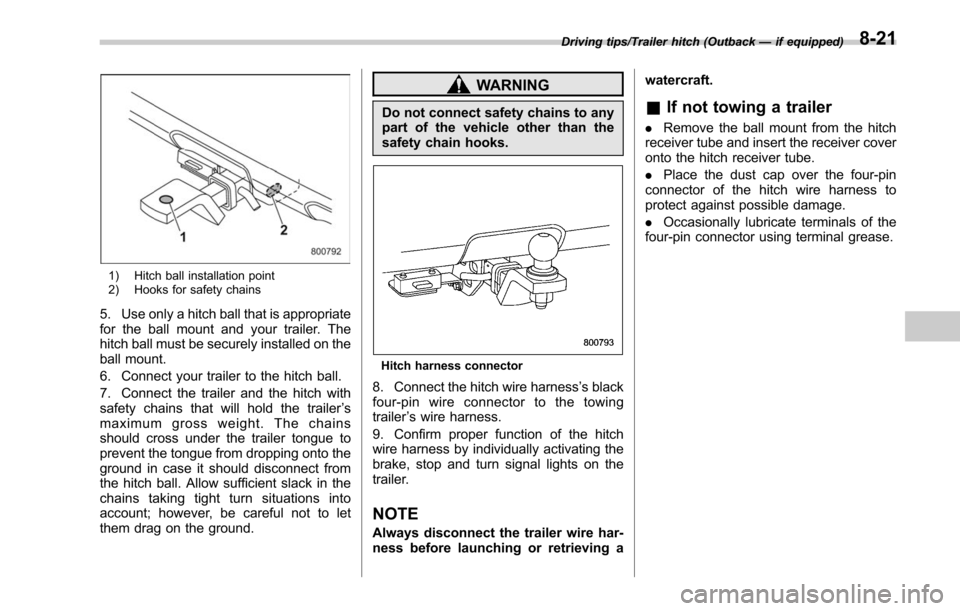
1) Hitch ball installation point
2) Hooks for safety chains
5. Use only a hitch ball that is appropriate
for the ball mount and your trailer. The
hitch ball must be securely installed on the
ball mount.
6. Connect your trailer to the hitch ball.
7. Connect the trailer and the hitch with
safety chains that will hold the trailer’s
maximum gross weight. The chains
should cross under the trailer tongue to
prevent the tongue from dropping onto the
ground in case it should disconnect from
the hitch ball. Allow sufficient slack in the
chains taking tight turn situations into
account; however, be careful not to let
them drag on the ground.
WARNING
Do not connect safety chains to any
part of the vehicle other than the
safety chain hooks.
Hitch harness connector
8. Connect the hitch wire harness ’s black
four-pin wire connector to the towing
trailer ’s wire harness.
9. Confirm proper function of the hitch
wire harness by individually activating the
brake, stop and turn signal lights on the
trailer.
NOTE
Always disconnect the trailer wire har-
ness before launching or retrieving a watercraft.
&
If not towing a trailer
. Remove the ball mount from the hitch
receiver tube and insert the receiver cover
onto the hitch receiver tube.
. Place the dust cap over the four-pin
connector of the hitch wire harness to
protect against possible damage.
. Occasionally lubricate terminals of the
four-pin connector using terminal grease.
Driving tips/Trailer hitch (Outback —if equipped)8-21
Page 470 of 610
ground.
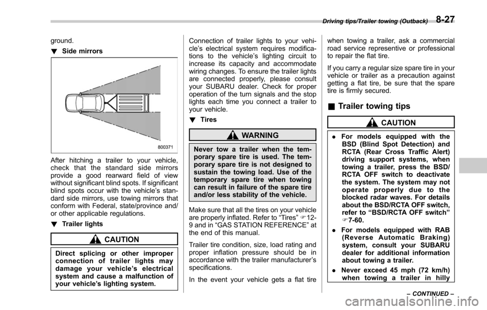
!Side mirrors
After hitching a trailer to your vehicle,
check that the standard side mirrors
provide a good rearward field of view
without significant blind spots. If significant
blind spots occur with the vehicle’ s stan-
dard side mirrors, use towing mirrors that
conform with Federal, state/province and/
or other applicable regulations.
! Trailer lights
CAUTION
Direct splicing or other improper
connection of trailer lights may
damage your vehicle ’s electrical
system and cause a malfunction of
your vehicle ’s lighting system. Connection of trailer lights to your vehi-
cle
’s electrical system requires modifica-
tions to the vehicle ’s lighting circuit to
increase its capacity and accommodate
wiring changes. To ensure the trailer lights
are connected properly, please consult
your SUBARU dealer. Check for proper
operation of the turn signals and the stop
lights each time you connect a trailer to
your vehicle.
! Tires
WARNING
Never tow a trailer when the tem-
porary spare tire is used. The tem-
porary spare tire is not designed to
sustain the towing load. Use of the
temporary spare tire when towing
can result in failure of the spare tire
and/or less stability of the vehicle.
Make sure that all the tires on your vehicle
are properly inflated. Refer to “Tires”F 12-
9 and in “GAS STATION REFERENCE ”at
the end of this manual.
Trailer tire condition, size, load rating and
proper inflation pressure should be in
accordance with the trailer manufacturer ’s
specifications.
In the event your vehicle gets a flat tire when towing a trailer, ask a commercial
road service representive or professional
to repair the flat tire.
If you carry a regular size spare tire in your
vehicle or trailer as a precaution against
getting a flat tire, be sure that the spare
tire is firmly secured.
&
Trailer towing tips
CAUTION
. For models equipped with the
BSD (Blind Spot Detection) and
RCTA (Rear Cross Traffic Alert)
driving support systems, when
towing a trailer, press the BSD/
RCTA OFF switch to deactivate
the system. The system may not
operate properly due to the
blocked radar waves. For details
about the BSD/RCTA OFF switch,
refer to “BSD/RCTA OFF switch ”
F 7-60.
. For models equipped with RAB
(Reverse Automatic Braking)
system, consult your SUBARU
dealer for additional information
about towing a trailer.
. Never exceed 45 mph (72 km/h)
when towing a trailer in hilly
Driving tips/Trailer towing (Outback)
–CONTINUED –8-27
Page 484 of 610
Jump starting
WARNING
.Battery fluid is SULFURIC ACID.
Do not let it come in contact with
the eyes, skin, clothing or the
vehicle.
If battery fluid gets on you,
thoroughly flush the exposed
area with water immediately. Get
medical help if the fluid has
entered your eyes.
If battery fluid is accidentally
swallowed, immediately drink a
large amount of milk or water,
and obtain immediate medical
help.
Keep everyone including chil-
dren away from the battery.
. The gas generated by a battery
explodes if a flame or spark is
brought near it. Do not smoke or
light a match while jump starting.
. Never attempt jump starting if the
discharged battery is frozen. It
could cause the battery to burst
or explode.
. Whenever working on or around
a battery, always wear suitable eye protectors, and remove metal
objects such as rings, bands or
other metal jewelry.
. Be sure the jumper cables and
clamps on them do not have
loose or missing insulation.
. Do not jump start unless cables
in suitable condition are avail-
able.
. A running engine can be danger-
ous. Keep your fingers, hands,
clothing, hair and tools away
from the cooling fan, belts and
any other moving engine parts.
Removing rings, watches and
ties is advisable.
. Jump starting is dangerous if it is
done incorrectly. If you are un-
sure about the proper procedure
for jump starting, consult a com-
petent mechanic.
When your vehicle does not start due to a
run down (discharged) battery, the vehicle
may be jump started by connecting your
battery to another battery (called the
booster battery) with jumper cables.
& How to jump start
1. Make sure the booster battery is 12
volts and the negative terminal is
grounded.
2. If the booster battery is in another
vehicle, do not let the two vehicles touch.
3. Turn off all unnecessary lights and
accessories.
4. Connect the jumper cables exactly in
the sequence illustrated.
In case of emergency/Jump starting
–CONTINUED –9-11
Page 543 of 610
Maintenance and service/Installation of accessories
Contact your SUBARU dealer for repairs.Installation of accessories
Always consult your SUBARU dealer
before installing fog lights or any other
electrical equipment in your vehicle. Such
accessories may cause the electronic
system to malfunction if they are incor-
rectly installed or if they are not suited for
the vehicle. We recommend that you
install only genuine SUBARU accessories
on your vehicle.
Replacing bulbs
WARNING
Bulbs may become very hot while
illuminated. Before replacing bulbs,
turn off the lights and wait until the
bulbs cool down, Otherwise, there is
the risk of sustaining a burn injury.
CAUTION
Replace any bulb only with a new
bulb of the specified wattage. Using
a bulb of different wattage could
result in a fire. For the specified
wattage of each bulb, refer to“Bulb
chart ”F12-14. For replacement,
contact your SUBARU dealer.
& HID headlights (if equipped)
WARNING
High-intensity-discharge (HID) bulbs
are used for the low beams of the
headlights. These HID bulbs use an
extremely high voltage. To avoid the
risk of an electric shock that could
result in serious injury, observe the
11-40
Page 569 of 610
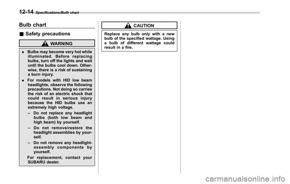
Specifications/Bulb chart
Bulb chart
&Safety precautions
WARNING
. Bulbs may become very hot while
illuminated. Before replacing
bulbs, turn off the lights and wait
until the bulbs cool down. Other-
wise, there is a risk of sustaining
a burn injury.
. For models with HID low beam
headlights, observe the following
precautions. Not doing so carries
the risk of an electric shock that
could result in serious injury
because the HID bulbs use an
extremely high voltage.
– Do not replace any headlight
bulbs (both low beam and
high beam) by yourself.
– Do not remove/restore the
headlight assemblies by your-
self.
– Do not remove any headlight-
assembly components by
yourself.
For replacement, contact your SUBARU dealer.
CAUTION
Replace any bulb only with a new
bulb of the specified wattage. Using
a bulb of different wattage could
result in a fire.
12-14