2017 SUBARU LEGACY change wheel
[x] Cancel search: change wheelPage 401 of 610

Starting and operating/Continuously variable transmission
1) Upshift indicator
2) Downshift indicator
3) Gear position indicator
When the manual mode is selected, the
gear position indicator and upshift indica-
tor and/or downshift indicator on the
combination meter illuminate. The gear
position indicator shows the currently
selected gear in the 1st-to-6th gear range.
The upshift and downshift indicators show
when a gearshift is possible. When the
upshift indicator“
”is on, upshifting is
possible. When the downshift indicator
“
” is on, downshifting is possible. When
both indicators are on, upshifting and
downshifting are both possible. When the
vehicle stops (for example, at traffic
signals), the downshift indicator turns off.
Gearshifts can be performed using the shift paddle behind the steering wheel.
To upshift to the next higher gear position,
pull the shift paddle that has
“+”indicated
on it. To downshift to the next lower gear
position, pull the shift paddle that has “–”
indicated on it.
To deselect the manual mode, return the
select lever to the “D”position from the “M”
position.
While driving with the select lever in the
“ D ” position, if you change gears by
operating the shift paddle, the gear posi-
tion indicator light illuminates and shows
the current gear condition.
CAUTION
Do not place or hang anything on
the shift paddles. Doing so may result in accidental gear shifting.
NOTE
Please read the following points care-
fully and bear them in mind when using
the manual mode.
.
If you attempt to shift down when
the engine speed is too high, i.e., when
a downshift would push the tachometer
needle beyond the red zone, beeps will
be emitted to warn you that the down-
shift is not possible.
. If you attempt to shift up when the
vehicle speed is too low, the transmis-
sion will not respond.
. You can perform a skip-shift (for
example, from 4th to 2nd) by operating
the shift paddle twice in rapid succes-
sion.
. The transmission automatically se-
lects 1st gear when the vehicle stops
moving.
. If the temperature of the transmis-
sion fluid becomes too high, the “AT
OIL TEMP ”warning light will illuminate.
Immediately stop the vehicle in a safe
place and let the engine idle until the
warning light turns off.
7-30
Page 413 of 610

Starting and operating/Parking your vehicle
sealant, the tire pressure warning
valve and transmitter may not
operate properly. If a liquid sea-
lant is used, contact your nearest
SUBARU dealer or other qualified
service shop as soon as possi-
ble. Make sure to replace the tire
pressure warning valve and
transmitter when replacing the
tire. You may reuse the wheel if
there is no damage to it and if the
sealant residue is properly
cleaned off. Do not inject any tire
liquid or aerosol tire sealant into
the tires, as this may cause a
malfunction of the tire pressure
sensors. If the light illuminates
steadily after blinking for ap-
proximately one minute,
promptly contact a SUBARU
dealer to have the system in-
spected.CAUTION
Do not place metal film or any metal
parts under the driver’s seat. This
may cause poor reception of the
signals from the tire pressure sen-
sors, and the tire pressure monitor-
ing system will not function prop-
erly.
FCC ID: CWTWD1U848
NOTE
This device complies with Part 15 of
the FCC Rules. Operation is subject to
the following two conditions: (1) This
device may not cause harmful inter-
ference, and (2) this device must
accept any interference received, in-
cluding interference that may cause
undesired operation.
FCC CAUTION
Changes or modifications not ex-
pressly approved by the party respon-
sible for compliance could void the
user ’s authority to operate the equip-
ment.
Parking your vehicle
WARNING
. Never leave unattended children
or pets in the vehicle. They could
accidentally injure themselves or
others through inadvertent op-
eration of the vehicle. Also, on
hot or sunny days, the tempera-
ture in a closed vehicle could
quickly become high enough to
cause severe or possibly fatal
injuries to them.
. Do not park the vehicle over
flammable materials such as dry
grass, waste paper or rags, as
they may burn easily if they come
near hot engine or exhaust sys-
tem parts.
. Be sure to stop the engine if you
take a nap in the vehicle. If
engine exhaust gas enters the
passenger compartment, occu-
pants in the vehicle could die
from carbon monoxide (CO) con-
tained in the exhaust gas.
7-42
Page 468 of 610

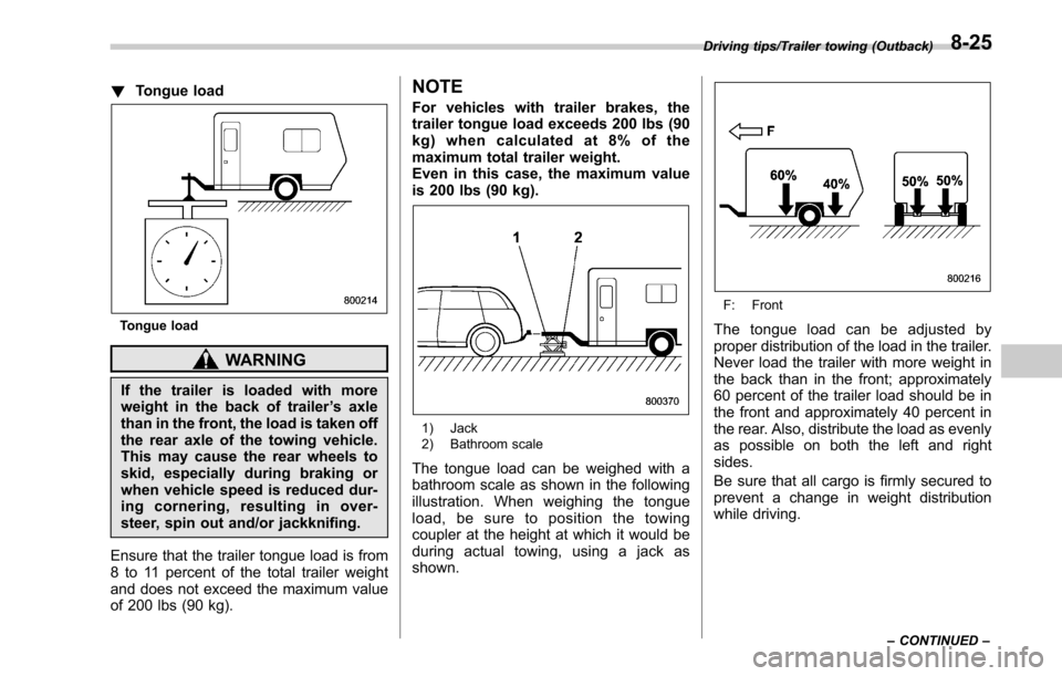
!Tongue load
Tongue load
WARNING
If the trailer is loaded with more
weight in the back of trailer ’s axle
than in the front, the load is taken off
the rear axle of the towing vehicle.
This may cause the rear wheels to
skid, especially during braking or
when vehicle speed is reduced dur-
ing cornering, resulting in over-
steer, spin out and/or jackknifing.
Ensure that the trailer tongue load is from
8 to 11 percent of the total trailer weight
and does not exceed the maximum value
of 200 lbs (90 kg).
NOTE
For vehicles with trailer brakes, the
trailer tongue load exceeds 200 lbs (90
kg) when calculated at 8% of the
maximum total trailer weight.
Even in this case, the maximum value
is 200 lbs (90 kg).
1) Jack
2) Bathroom scale
The tongue load can be weighed with a
bathroom scale as shown in the following
illustration. When weighing the tongue
load, be sure to position the towing
coupler at the height at which it would be
during actual towing, using a jack as
shown.
F: Front
The tongue load can be adjusted by
proper distribution of the load in the trailer.
Never load the trailer with more weight in
the back than in the front; approximately
60 percent of the trailer load should be in
the front and approximately 40 percent in
the rear. Also, distribute the load as evenly
as possible on both the left and right
sides.
Be sure that all cargo is firmly secured to
prevent a change in weight distribution
while driving.
Driving tips/Trailer towing (Outback)
–CONTINUED –8-25
Page 471 of 610

Driving tips/Trailer towing (Outback)
country on hot days.
. When towing a trailer, steering,
stability, stopping distance and
braking performance will be dif-
ferent when compared to normal
operation. You should never
drive at excessive speeds but
always employ extra caution
when towing a trailer. You should
also keep the following tips in
mind.
. When parking on a steep slope
with a trailer attached to your
vehicle, the braking power of the
electronic parking brake may not
be sufficient since strong brak-
ing power is needed.
! Before starting out on a trip
. Check the towing regulations for trailer
or caravan vehicles that vary by state/
region. Failure to comply with the proce-
dures set forth will not only compromise
your safety, but will also negate your
insurance coverage and/or may violate
the state road and traffic acts and regula-
tions.
. Check that the vehicle and vehicle-to-
hitch mounting are in good condition. If
any problems are apparent, do not tow the
trailer. .
Check that the vehicle rests horizon-
tally with the trailer attached. If the vehicle
is tipped sharply up at the front and down
at the rear, check the total trailer weight,
GVW, GAWs and tongue load again, then
confirm that the load and its distribution
are acceptable.
. Check that the tire pressures are
correct.
. Check that the vehicle and trailer are
connected properly. Confirm that
–the trailer tongue is connected
properly to the hitch ball.
– the trailer lights connector is con-
nected properly and trailer ’s stop lights
illuminate when the vehicle’ s brake
pedal is pressed, and that the trailer ’s
turn signal lights flash when the
vehicle’ s turn signal lever is operated.
– the safety chains are connected
properly.
– all cargo in the trailer is secured
safely in position.
– the side mirrors provide a good
rearward field of view without a sig-
nificant blind spot.
. Sufficient time should be taken to learn
the “feel ”of the vehicle/trailer combination
before starting out on a trip. In an area free
of traffic, practice turning, stopping and
backing up. !
Driving with a trailer
. You should allow for considerably more
stopping distance when towing a trailer.
Avoid sudden braking because it may
result in skidding or jackknifing and loss of
control.
. Avoid abrupt starts and sudden accel-
erations. For MT models, always start out
in first gear and release the clutch pedal at
moderate engine revolution.
. Avoid uneven steering, sharp turns and
rapid lane changes.
. Slow down before turning. Make a
longer than normal turning radius because
the trailer wheels will be closer than the
vehicle wheels to the inside of the turn. In
a tight turn, the trailer could hit your
vehicle.
. Crosswinds will adversely affect the
handling of your vehicle and trailer, caus-
ing sway. Crosswinds can be due to
weather conditions or the passing of large
trucks or buses. If swaying occurs, firmly
grip the steering wheel and promptly begin
decelerating your vehicle at a gradual
pace.
. When passing other vehicles, consid-
erable distance is required because of the
added weight and length caused by
attaching the trailer to your vehicle.
8-28
Page 529 of 610
![SUBARU LEGACY 2017 6.G Owners Manual Maintenance and service/Tires and wheels
Outside
temperature Adjusted pressure
[psi (kPa, kgf/cm2)]
Front Rear
30 8F( −18C) 38 (265, 2.65) 36 (250, 2.5)
10 8F( −12 8C) 40 (280, 2.8) 38 (265, 2.65) SUBARU LEGACY 2017 6.G Owners Manual Maintenance and service/Tires and wheels
Outside
temperature Adjusted pressure
[psi (kPa, kgf/cm2)]
Front Rear
30 8F( −18C) 38 (265, 2.65) 36 (250, 2.5)
10 8F( −12 8C) 40 (280, 2.8) 38 (265, 2.65)](/manual-img/17/7291/w960_7291-528.png)
Maintenance and service/Tires and wheels
Outside
temperature Adjusted pressure
[psi (kPa, kgf/cm2)]
Front Rear
30 8F( −18C) 38 (265, 2.65) 36 (250, 2.5)
10 8F( −12 8C) 40 (280, 2.8) 38 (265, 2.65)
−10 8F( −23 8C) 42 (295, 2.95) 40 (280, 2.8)
If the low tire pressure warning light
illuminates when you drive the vehicle in
cold outside air after adjusting the tire
pressures in a warm garage, re-adjust the
tire pressures using the method described
above. Then, increase the vehicle speed
to at least 20 mph (32 km/h) and check to
see that the low tire pressure warning light
goes off a few minutes later. If the low tire
pressure warning light does not go off, the
tire pressure monitoring system may not
be functioning normally. In this event, go
to a SUBARU dealer to have the system
inspected as soon as possible.
While the vehicle is driven, friction be-
tween tires and the road surface causes
the tires to warm up. After illumination of
the low tire pressure warning light, any
increase in the tire pressures caused by
an increase in the outside air temperature
or by an increase in the temperature in the
tires can cause the low tire pressure
warning light to go off. System resetting is necessary when the
wheels are changed (for example, a
switch to snow tires) and new TPMS
valves are installed on the newly fitted
wheels. Have this work performed by a
SUBARU dealer following wheel replace-
ment.
It may not be possible to install TPMS
valves on certain wheels that are on the
market. Therefore, if you change the
wheels (for example, a switch to snow
tires), use wheels that have the same part
number as the standard-equipment
wheels. Without four operational TPMS
valve/sensors on the wheels, the TPMS
will not fully function and the warning light
in the instrument panel will illuminate
steadily after blinking for approximately
one minute.
When a tire is replaced, adjustments are
necessary to ensure continued normal
operation of the tire pressure monitoring
system. As with wheel replacement, there-
fore, you should have the work performed
by a SUBARU dealer.
WARNING
If the low tire pressure warning light
does not illuminate briefly after the
ignition switch is turned ON or the
light illuminates steadily after blink-ing for approximately one minute,
you should have your Tire Pressure
Monitoring System checked at a
SUBARU dealer as soon as possi-
ble.
If this light illuminates while driving,
never brake suddenly. Instead, per-
form the following procedure. Other-
wise an accident involving serious
vehicle damage and serious perso-
nal injury could occur.
1) Keep driving straight ahead while
gradually reducing speed.
2) Slowly pull off the road to a safe place.
If this light still illuminates while
driving after adjusting the tire pres-
sure, a tire may have significant
damage and a fast leak that causes
the tire to lose air rapidly. If you have
a flat tire, replace it with a spare tire
as soon as possible.
When a spare tire is mounted or a
wheel rim is replaced without the
original pressure sensor/transmitter
being transferred, the low tire pres-
sure warning light will illuminate
steadily after blinking for approxi-
mately one minute. This indicates
the TPMS is unable to monitor all
four road wheels. Contact your
11-26
Page 533 of 610

Maintenance and service/Tires and wheels
the direction mark facing forward.
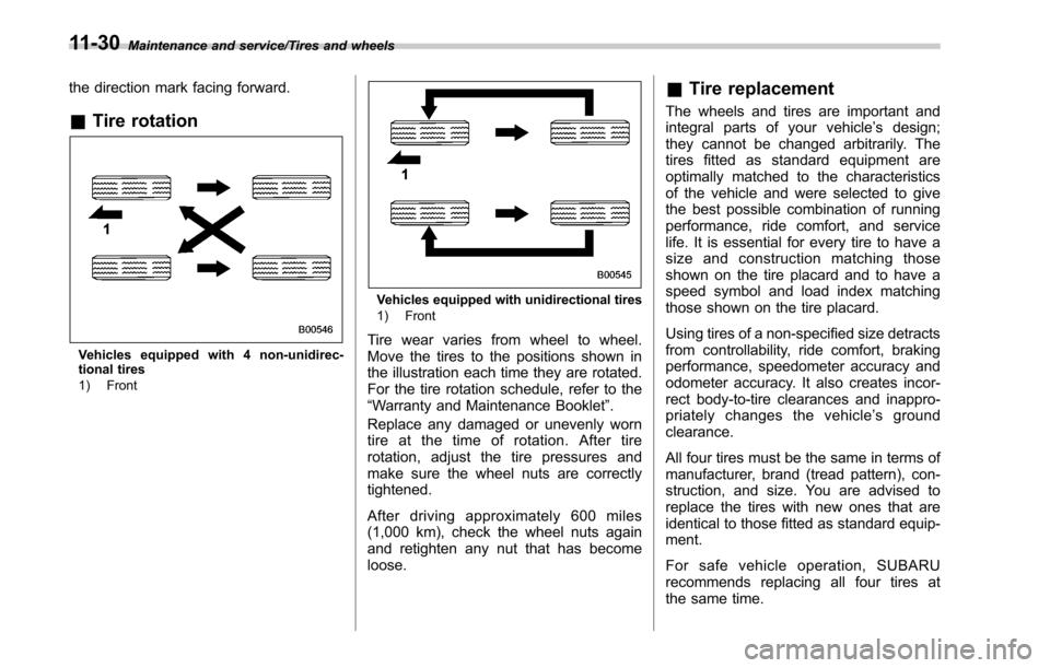
&Tire rotation
Vehicles equipped with 4 non-unidirec-
tional tires
1) Front
Vehicles equipped with unidirectional tires
1) Front
Tire wear varies from wheel to wheel.
Move the tires to the positions shown in
the illustration each time they are rotated.
For the tire rotation schedule, refer to the
“Warranty and Maintenance Booklet ”.
Replace any damaged or unevenly worn
tire at the time of rotation. After tire
rotation, adjust the tire pressures and
make sure the wheel nuts are correctly
tightened.
After driving approximately 600 miles
(1,000 km), check the wheel nuts again
and retighten any nut that has become
loose.
& Tire replacement
The wheels and tires are important and
integral parts of your vehicle’ s design;
they cannot be changed arbitrarily. The
tires fitted as standard equipment are
optimally matched to the characteristics
of the vehicle and were selected to give
the best possible combination of running
performance, ride comfort, and service
life. It is essential for every tire to have a
size and construction matching those
shown on the tire placard and to have a
speed symbol and load index matching
those shown on the tire placard.
Using tires of a non-specified size detracts
from controllability, ride comfort, braking
performance, speedometer accuracy and
odometer accuracy. It also creates incor-
rect body-to-tire clearances and inappro-
priately changes the vehicle’ s ground
clearance.
All four tires must be the same in terms of
manufacturer, brand (tread pattern), con-
struction, and size. You are advised to
replace the tires with new ones that are
identical to those fitted as standard equip-
ment.
For safe vehicle operation, SUBARU
recommends replacing all four tires at
the same time.
11-30
Page 535 of 610

Maintenance and service/Aluminum wheels
Aluminum wheels
Aluminum wheels can be scratched and
damaged easily. Handle them carefully to
maintain their appearance, performance,
and safety.
.When any of the wheels is removed
and replaced for tire rotation or to change
a flat, always check the tightness of the
wheel nuts after driving approximately 600
miles (1,000 km). If any nut is loose,
tighten it to the specified torque.
. Never apply oil to the threaded parts,
wheel nuts, or tapered surface of the
wheel.
. Never let the wheel rub against sharp
protrusions or curbs.
. When wheel nuts, balance weights, or
the center cap is replaced, be sure to
replace them with genuine SUBARU parts
designed for aluminum wheels.
Windshield washer fluid
CAUTION
Never use engine coolant as washer
fluid because it could cause paint
damage.
Windshield washer fluid warning indicator
When there is only a small amount of
washer fluid remaining, the windshield
washer fluid warning indicator will appear.
When this occurs, refill the washer fluid as
follows.
1) “FULL ”mark
Remove the washer tank filler cap, then
add fluid until it reaches the “FULL”mark
on the tank.
Use windshield washer fluid. If windshield
washer fluid is unavailable use clean
water.
In areas where water freezes in winter,
use an anti-freeze type windshield washer
fluid. SUBARU Windshield Washer Fluid
contains 58.5% methyl alcohol and 41.5%
surfactant, by volume. Its freezing tem-
perature varies according to how much it
is diluted, as indicated in the following
table.
11-32
Page 557 of 610

Specifications/Specifications
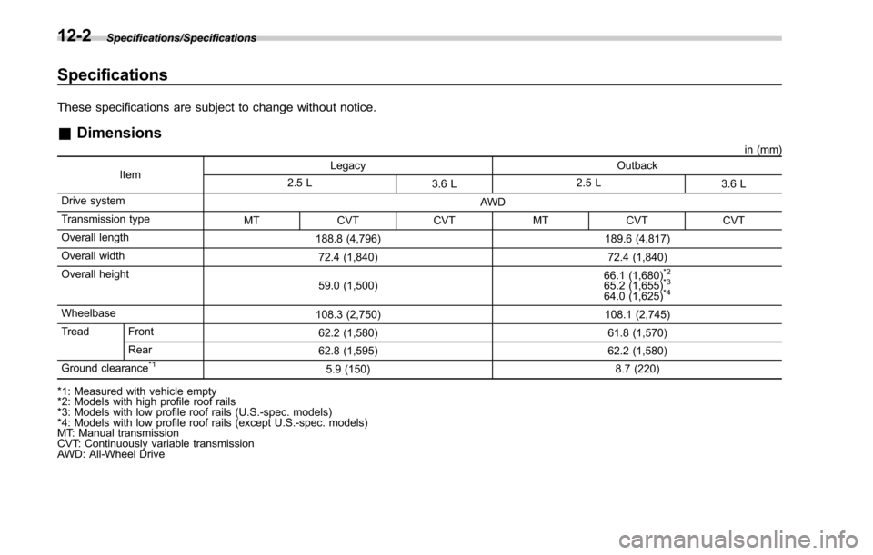
Specifications
These specifications are subject to change without notice.
&Dimensions
in (mm)
Item Legacy Outback
2.5 L 3.6 L 2.5 L
3.6 L
Drive system AWD
Transmission type MT CVT CVT MT CVT CVT
Overall length 188.8 (4,796) 189.6 (4,817)
Overall width 72.4 (1,840) 72.4 (1,840)
Overall height 59.0 (1,500) 66.1 (1,680)
*2
65.2 (1,655)*3
64.0 (1,625)*4
Wheelbase
108.3 (2,750) 108.1 (2,745)
Tread Front 62.2 (1,580) 61.8 (1,570)
Rear 62.8 (1,595) 62.2 (1,580)
Ground clearance
*15.9 (150) 8.7 (220)
*1: Measured with vehicle empty
*2: Models with high profile roof rails
*3: Models with low profile roof rails (U.S.-spec. models)
*4: Models with low profile roof rails (except U.S.-spec. models)
MT: Manual transmission
CVT: Continuously variable transmission
AWD: All-Wheel Drive
12-2