2017 SUBARU FORESTER ac control
[x] Cancel search: ac controlPage 180 of 634

Inside warningchime Outside warning
chime Access key
warning light on
meter Operation indica-
tor on push-button
ignition switch Status Action
Long beep
(continuous) —— — Select lever position warning:
The engine is turned off by press-
ing the push-button ignition switch
and the select lever is in a position
other than the
“P ”position. Start the engine, shift the select
lever to the
“P ”position, switch the
push-button ignition switch to “OFF ”
and exit the vehicle.
Long beep
(continuous) —— — Select lever position warning:
The driver
’s door was opened while
the push-button ignition switch is in
a position other than “OFF ”and the
select lever is in a position other
than the “P ”position. Shift the select lever to the
“P ”
position, switch the push-button
ignition switch to “OFF ”and exit the
vehicle.
Ding —— — The battery of the access key is
low.Replace the battery of the access
key.
Ding —— Flashes in green
(15 seconds max.) Steering lock warning:
The engine start procedure was
performed, but the steering is still
locked. While turning the steering wheel
right and left lightly, depress the
brake pedal and press the push-
button ignition switch.
Ding —— Flashes in orangeSystem malfunction warning:
A malfunction was detected in the
power system or steering lock. Contact a SUBARU dealer imme-
diately and have the vehicle in-
spected.
NOTEAn electronic chirp will sound while the select lever is in the
“R ” position. In this case, the select lever position warning chime
will not sound.
Instruments and controls/Warning and indicator lights
–CONTINUED –3-29
Page 181 of 634

Instruments and controls/Warning and indicator lights
&Security indicator light
This indicator light shows the status of the
alarm system. It also indicates operation
of the immobilizer system.
!Alarm system
It blinks to show the driver the operational
status of the alarm system. For detailed
information, refer to “Alarm system ”F 2-
25.
! Immobilizer system
The security indicator light starts blinking
in the following conditions.
For models with “keyless access with
push-button start system ”:
. Immediately after the push-button igni-
tion switch is turned to the “OFF”position.
. Immediately after the driver ’s door is
opened or closed when all of the following
conditions are met.
–The push-button ignition switch is in
the “ON ”or “ACC ”position.
– The access key is outside the
vehicle.
– The engine is not running.
In the event that the push-button ignition
switch is pressed to turn it on or to start
the engine carrying an unauthorized key
(for example, the key is unregistered or
the ID code does not match), the power is not switched to
“ON ”and the security
indicator light continues blinking.
For models without “keyless access
with push-button start system ”:
. Approximately 60 seconds after the
ignition switch is turned from the “ON ”
position to the “ACC”or “LOCK ”position.
. Immediately after the key is pulled out.
If the indicator light does not blink in the
above conditions, it may indicate that
immobilizer system may be malfunction-
ing. Contact your nearest SUBARU dealer
immediately.
In the event that an unauthorized key (for
example, an unauthorized duplicate) is
used to start the engine, the security
indicator light illuminates. For details
about the immobilizer system, refer to
“Immobilizer ”F 2-3.
NOTE
. The security indicator light remains
off in the following conditions. It means
that the matching of the ID code is
completed and the immobilizer system
is deactivated, and it does not indicate
a malfunction.
Models with “keyless access with
push-button start system ”:
– while the engine is running
– the push-button ignition switch
has been turned to the “ON ”or
“ ACC” position and the driver ’s
door has not been opened or closed
Models without “keyless access
with push-button start system ”:
– while the engine is running
– for approximately 60 seconds
after the ignition switch is turned
from the “ON ”position to the
“ ACC ”or “LOCK ”position
– when the ignition switch is in the
“ ON ”position
. Even if a malfunction occurs, such
as if the security indicator light flashes
irregularly, it will not affect the func-
tionality of the immobilizer system.
3-30
Page 182 of 634

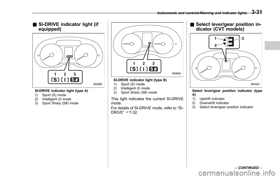
&SI-DRIVE indicator light (if
equipped)
SI-DRIVE indicator light (type A)
1) Sport (S) mode
2) Intelligent (I) mode
3) Sport Sharp (S#) mode
SI-DRIVE indicator light (type B)
1) Sport (S) mode
2) Intelligent (I) mode
3) Sport Sharp (S#) mode
This light indicates the current SI-DRIVE
mode.
For details of SI-DRIVE mode, refer to “SI-
DRIVE ”F 7-32.
& Select lever/gear position in-
dicator (CVT models)
Select lever/gear position indicator (type
A)
1) Upshift indicator
2) Downshift indicator
3) Select lever/gear position indicator
Instruments and controls/Warning and indicator lights
–CONTINUED –
3-31
Page 183 of 634

Instruments and controls/Warning and indicator lights
Select lever/gear position indicator (type
B)
1) Upshift indicator
2) Downshift indicator
3) Select lever/gear position indicator
This indicator shows the position of the
select lever.
For models with manual mode, when the
manual mode is selected, the gear posi-
tion indicator (which shows the current
gear selection) and the upshift/downshift
indicator light up. Refer to“Continuously
variable transmission ”F 7-24.
For models with SI-DRIVE, the upshift/
downshift indicators are switched off while
the Sport Sharp (S#) mode is selected.
&Turn signal indicator
lights
These lights show the operation of the turn
signal or lane change signal.
If the indicator lights do not blink or blink
rapidly, the turn signal bulb may be burned
out. Replace the bulb as soon as possible.
Refer to “Replacing bulbs ”F 11-39.
&High beam indicator
light
This light shows that the headlights are in
the high beam mode.
This indicator light also illuminates when
the headlight flasher is operated.
&High beam assist indi-
cator light (if equipped)
This light illuminates when the high beam
assist function is activated. For details
about the high beam assist function, refer
to “High beam assist function ”F 3-95.
&Cruise control indica-
tor light (if equipped)
This light illuminates when the cruise
control main button is pressed to activate
the cruise control function. For details,
refer to “To set cruise control ”F 7-53.
CAUTION
If the CHECK ENGINE warning light/
malfunction indicator light illumi-
nates, the cruise control indicator
light flashes at the same time. At
this time, avoid driving at high
speed and have your vehicle in-
spected at a SUBARU dealer as
soon as possible.
&Cruise control set in-
dicator light (if
equipped)
This light illuminates when vehicle speed
has been set to use the cruise control
function. Refer to “To set cruise control ”
F 7-53.
&Automatic headlight
beam leveler warning
light (if equipped)
This light illuminates when the automatic
headlight beam leveler does not operate
normally.
If this light illuminates while driving or does
not turn off approximately 3 seconds after
turning the ignition switch to the “ON”
position, have your vehicle inspected at
your SUBARU dealer.
3-32
Page 184 of 634

&Steering Responsive
Headlight warning light/
Steering Responsive
Headlight OFF indicator
light (if equipped)
This light illuminates when the Steering
Responsive Headlight OFF switch is
pressed to deactivate the Steering Re-
sponsive Headlight. Also, the light flashes
when a malfunction occurs in the Steering
Responsive Headlight. Refer to“Steering
Responsive Headlight (SRH) ”F 3-99.
&Front fog light indicator
light (if equipped)
This indicator light illuminates while the
front fog lights are illuminated.
&Headlight indicator
light (if equipped)
This indicator light illuminates under the
following conditions.
. when the light switch is turned to the
“
” or “”position
. when the light control switch is in the
“AUTO ”position and the headlights illumi-
nate automatically
&X-mode indicator light
(if equipped)
This light illuminates while the X-mode is
activated. It will turn off when the X-mode
is deactivated. Refer to “To activate/
deactivate the X-mode ”F 7-43.
&Hill descent control
indicator light (if
equipped)
This indicator illuminates while the hill
descent control function is in standby. It
will flash while the hill descent control
function is operating. It will turn off when
the hill descent control function is not
available. Refer to “Hill descent control
function ”F 7-44.
&Steering responsive
fog lights warning indi-
cator/Steering respon-
sive fog lights OFF in-
dicator (if equipped)
NOTE
For details about the steering respon-
sive fog lights system, refer to “Steer-
ing responsive fog lights system ”F 3-
103. !
Steering responsive fog lights
warning indicator
This indicator starts blinking when the
steering responsive fog lights system
malfunctions. When this indicator is blink-
ing while the system is activated, contact
your SUBARU dealer for an inspection.
! Steering responsive fog lights OFF
indicator
This indicator appears when the steering
responsive fog lights system is deacti-
vated. This indicator disappears when the
system is activated.
&BSD/RCTA warning in-
dicator (if equipped)
This warning indicator appears when the
BSD/RCTA is malfunctioning.
For models with type A combination
meter, the BSD/RCTA warning indicator
will be shown on the combination meter.
For models with type B combination
meter, the BSD/RCTA warning indicator
will be shown on the multi information
display of the combination meter.
When this indicator appears, have your
vehicle inspected by your SUBARU dealer
as soon as possible.
Instruments and controls/Warning and indicator lights
–CONTINUED –3-33
Page 185 of 634

Instruments and controls/Information display (Mexico–spec. models)
&BSD/RCTA OFF indica-
tor (if equipped)
The indicator appears when the BSD/
RCTA OFF switch is pressed to deactivate
the BSD/RCTA.
For models with type A combination
meter, the BSD/RCTA OFF indicator will
be shown on the combination meter. For
models with type B combination meter, the
BSD/RCTA OFF indicator will be shown
on the multi information display of the
combination meter.
For details, refer to “BSD/RCTA ”F 7-58.
&RAB warning light (if
equipped)
This indicator illuminates if the Reverse
Automatic Braking System malfunctions.
Refer to “Reverse Automatic Braking
System ”F 7-66.
&RAB OFF indicator
light (if equipped)
This indicator illuminates when the Re-
verse Automatic Braking System is turned
OFF, or when the Reverse Automatic
Braking System is suspended temporarily.
Refer to “Reverse Automatic Braking
System ”F 7-66.
Information display (Mexico-
spec. models)
NOTE
If your vehicle is equipped with a color
multi function display, refer to “Multi
function display ”F 3-44.
1) Outside temperature indicator
2) Driving information display
3) Clock
With the ignition switch in the “ACC ”
position, the clock appears on the display.
Withtheignitionswitchinthe“ ON”
position, the outside temperature indica-
tor, driving information display and clock
all appear on the display.
& Outside temperature indica-
tor
This indicator displays the outside tem-
perature between −408 F( −408 C) and
122 8F (50 8C).
NOTE
The outside temperature indicator
shows the temperature around the
sensor. Therefore, the temperature in-
dication may differ from the actual
outside air temperature.
3-34
Page 186 of 634

!Road surface freeze warning indi-
cation
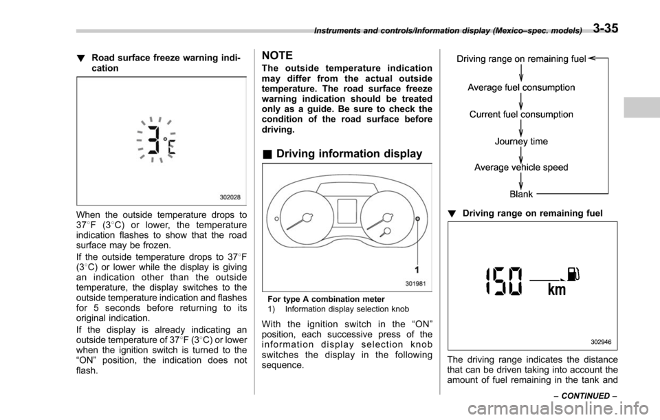
When the outside temperature drops to
378F(3 8C) or lower, the temperature
indication flashes to show that the road
surface may be frozen.
If the outside temperature drops to 37 8F
(3 8C) or lower while the display is giving
an indication other than the outside
temperature, the display switches to the
outside temperature indication and flashes
for 5 seconds before returning to its
original indication.
If the display is already indicating an
outside temperature of 37 8F(3 8C) or lower
when the ignition switch is turned to the
“ ON ”position, the indication does not
flash.
NOTE
The outside temperature indication
may differ from the actual outside
temperature. The road surface freeze
warning indication should be treated
only as a guide. Be sure to check the
condition of the road surface before
driving.
& Driving information display
For type A combination meter
1) Information display selection knob
Withtheignitionswitchinthe“ ON”
position, each successive press of the
information display selection knob
switches the display in the following
sequence.
! Driving range on remaining fuel
The driving range indicates the distance
that can be driven taking into account the
amount of fuel remaining in the tank and
Instruments and controls/Information display (Mexico –spec. models)
–CONTINUED –3-35
Page 187 of 634

Instruments and controls/Information display (Mexico–spec. models)
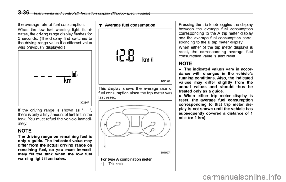
the average rate of fuel consumption.
When the low fuel warning light illumi-
nates, the driving range display flashes for
5 seconds. (The display first switches to
the driving range value if a different value
was previously displayed.)
If the driving range is shown as “”,
there is only a tiny amount of fuel left in the
tank. You must refuel the vehicle immedi-
ately.
NOTE
The driving range on remaining fuel is
only a guide. The indicated value may
differ from the actual driving range on
remaining fuel, so you must immedi-
ately fill the tank when the low fuel
warning light illuminates. !
Average fuel consumption
This display shows the average rate of
fuel consumption since the trip meter was
last reset.
For type A combination meter
1) Trip knob
Pressing the trip knob toggles the display
between the average fuel consumption
corresponding to the A trip meter display
and the average fuel consumption corre-
sponding to the B trip meter display.
When either of the trip meter displays is
reset, the corresponding average fuel
consumption value is also reset.
NOTE
.The indicated values vary in accor-
dance with changes in the vehicle ’s
running conditions. Also, the indicated
values may differ slightly from the
actual values and should thus be
treated only as a guide.
. When either trip meter display is
reset, the average fuel consumption
corresponding to that trip meter dis-
play is not shown until the vehicle has
subsequently covered a distance of 1
mile (or 1 km).
3-36