2017 SUBARU FORESTER brake light
[x] Cancel search: brake lightPage 450 of 634

mitter being transferred, the low
tire pressure warning light will
illuminate steadily after blinking
for approximately one minute.
This indicates the TPMS is un-
able to monitor all four road
wheels. Contact your SUBARU
dealer as soon as possible for
tire and sensor replacement and/
or system resetting.
. Do not inject any tire liquid or
aerosol tire sealant into the tires,
as this may cause a malfunction
of the tire pressure sensors. If
the light illuminates steadily after
blinking for approximately one
minute, promptly contact a
SUBARU dealer to have the sys-
tem inspected.
CAUTION
. Do not place metal film or any
metal parts in the cargo area.
This may cause poor reception of
the signals from the tire pressure
sensors, and the tire pressure
monitoring system will not func-
tion properly.
. FCC WARNING
Changes or modifications not expressly approved by the party
responsible for compliance
could void the user
’s authority
to operate the equipment.
NOTE
This device complies with Part 15 of
the FCC Rules. Operation is subject to
the following two conditions:
. U.S.-spec. models
FCC ID: CWTWD1U781
NOTE
This device complies with Part 15 of
the FCC Rules. Operation is subject to
the following two conditions: (1) This
device may not cause harmful inter-
ference, and (2) this device must
accept any interference received, in-
cluding interference that may cause
undesired operation.
Parking your vehicle
& Parking brake
To set the parking brake, depress the
brake pedal firmly and hold it down until
the parking brake lever is fully pulled up.
To release the parking brake, perform the
following procedure.
1. Pull the lever up slightly.
2. Press the release button.
3. Lower the lever while keeping the
button pressed.
When the parking brake is set while the
engine is running, the parking brake
warning light illuminates. After starting
the vehicle, be sure that the warning light
has turned off before the vehicle is driven.
Refer to “Brake system warning light ”F 3-
Starting and operating/Parking your vehicle
–CONTINUED –7-47
Page 453 of 634
Starting and operating/Hill start assist system
ditions.
.when the clutch pedal is depressed
while the brake pedal is also depressed
(MT models)
. when the vehicle has stopped with the
brake pedal depressed (CVT models)
Braking power is maintained temporarily
(for approximately 2 seconds) by the Hill
start assist system after the brake pedal is
released. The driver is therefore able to
start the vehicle in the same way as on a
level grade, just using the clutch pedal
(MT models only) and accelerator pedal
(all models).
If the braking power of the Hill start assist
system is insufficient after the brake pedal
is released, apply more braking power by
depressing the brake pedal again.
The Hill start assist system may not
operate on slight grades. Also, the Hill
start assist system does not operate in the
following cases.
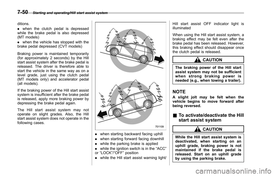
. when starting backward facing uphill
. when starting forward facing downhill
. while the parking brake is applied
. while the ignition switch is in the “ACC”
or “LOCK”/ “OFF”position
. while the Hill start assist warning light/ Hill start assist OFF indicator light is
illuminated
When using the Hill start assist system, a
braking effect may be felt even after the
brake pedal has been released. However,
this braking effect should disappear once
the clutch pedal is released.
CAUTION
The braking power of the Hill start
assist system may not be sufficient
when strong braking power is
needed (e.g., when towing a trailer).
NOTE
A slight jolt may be felt when the
vehicle begins to move forward after
being reversed.
&
To activate/deactivate the Hill
start assist system
CAUTION
While the Hill start assist system is
deactivated, when starting on an
uphill grade, braking power is not
maintained if the brake pedal is
released. Start on an uphill grade
by using the parking brake.
7-50
Page 454 of 634
You can activate/deactivate the Hill start
assist system according to the following
procedure.
NOTE
If you make an error when performing
any steps in the following procedure,
placetheignitionswitchinthe
“LOCK ”/“OFF ”position once and then
start over again.
! To deactivate
1. Park your vehicle in a flat and safe
location and apply the parking brake.
2. Turn the ignition switch to the “LOCK” /
“OFF ”position.
3. Restart the engine.
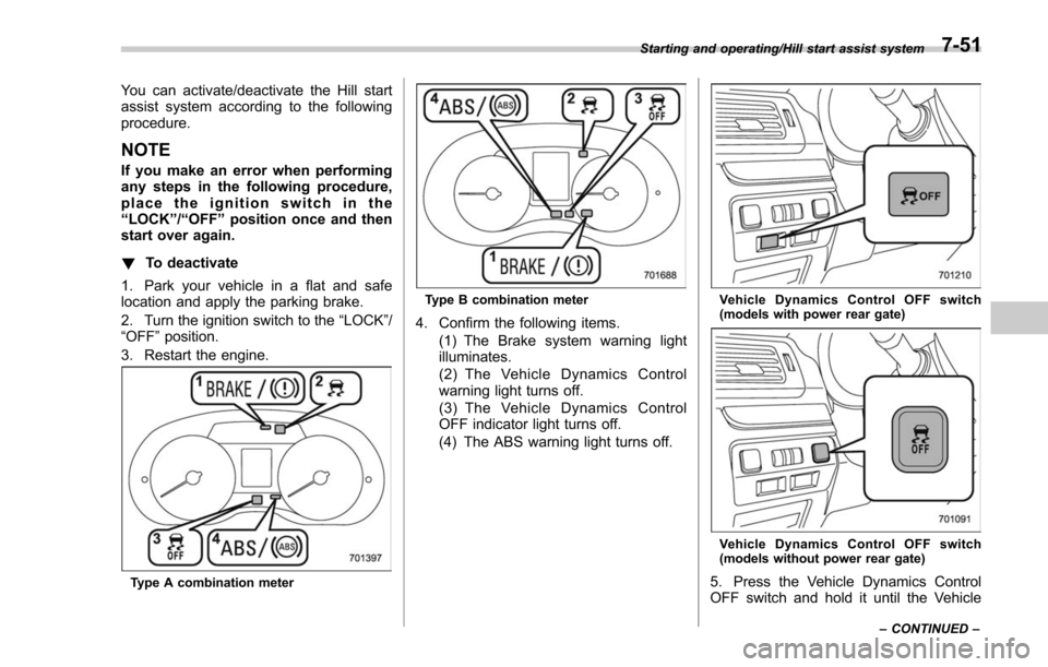
Type A combination meter
Type B combination meter
4. Confirm the following items. (1) The Brake system warning light
illuminates.
(2) The Vehicle Dynamics Control
warning light turns off.
(3) The Vehicle Dynamics Control
OFF indicator light turns off.
(4) The ABS warning light turns off.
Vehicle Dynamics Control OFF switch
(models with power rear gate)
Vehicle Dynamics Control OFF switch
(models without power rear gate)
5. Press the Vehicle Dynamics Control
OFF switch and hold it until the Vehicle
Starting and operating/Hill start assist system
–CONTINUED –7-51
Page 458 of 634
&To temporarily cancel the
cruise control
The cruise control can be temporarily
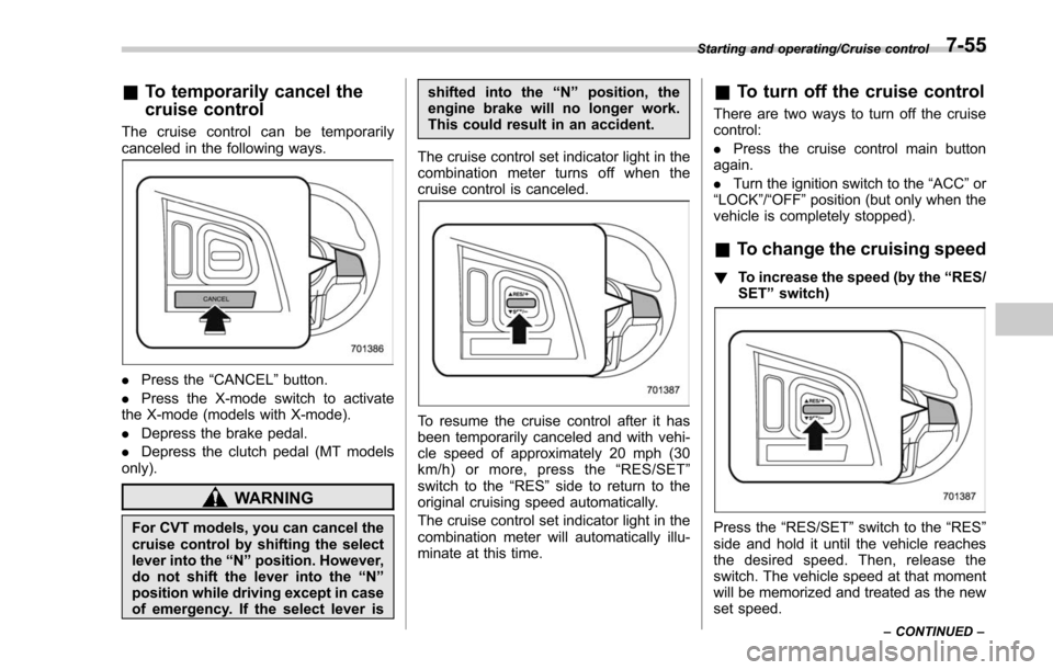
canceled in the following ways.
. Press the “CANCEL”button.
. Press the X-mode switch to activate
the X-mode (models with X-mode).
. Depress the brake pedal.
. Depress the clutch pedal (MT models
only).
WARNING
For CVT models, you can cancel the
cruise control by shifting the select
lever into the “N ” position. However,
do not shift the lever into the “N ”
position while driving except in case
of emergency. If the select lever is shifted into the
“N ” position, the
engine brake will no longer work.
This could result in an accident.
The cruise control set indicator light in the
combination meter turns off when the
cruise control is canceled.
To resume the cruise control after it has
been temporarily canceled and with vehi-
cle speed of approximately 20 mph (30
km/h) or more, press the “RES/SET ”
switch to the “RES ”side to return to the
original cruising speed automatically.
The cruise control set indicator light in the
combination meter will automatically illu-
minate at this time.
& To turn off the cruise control
There are two ways to turn off the cruise
control:
. Press the cruise control main button
again.
. Turn the ignition switch to the “ACC”or
“ LOCK ”/“OFF ”position (but only when the
vehicle is completely stopped).
& To change the cruising speed
! To increase the speed (by the “RES/
SET ”switch)
Press the “RES/SET ”switch to the “RES”
side and hold it until the vehicle reaches
the desired speed. Then, release the
switch. The vehicle speed at that moment
will be memorized and treated as the new
set speed.
Starting and operating/Cruise control
–CONTINUED –7-55
Page 460 of 634
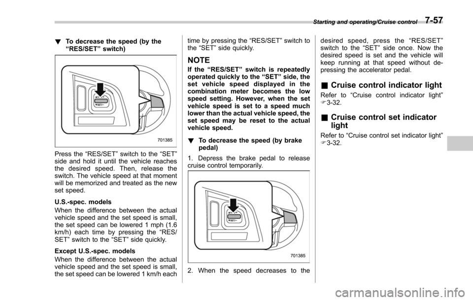
!To decrease the speed (by the
“RES/SET ”switch)
Press the “RES/SET”switch to the “SET”
side and hold it until the vehicle reaches
the desired speed. Then, release the
switch. The vehicle speed at that moment
will be memorized and treated as the new
set speed.
U.S.-spec. models
When the difference between the actual
vehicle speed and the set speed is small,
the set speed can be lowered 1 mph (1.6
km/h) each time by pressing the “RES/
SET ”switch to the “SET”side quickly.
Except U.S.-spec. models
When the difference between the actual
vehicle speed and the set speed is small,
the set speed can be lowered 1 km/h each time by pressing the
“RES/SET”switch to
the “SET ”side quickly.
NOTE
If the “RES/SET ”switch is repeatedly
operated quickly to the “SET ”side, the
set vehicle speed displayed in the
combination meter becomes the low
speed setting. However, when the set
vehicle speed is set to a speed much
lower than the actual vehicle speed, the
set speed may be reset to the actual
vehicle speed.
! To decrease the speed (by brake
pedal)
1. Depress the brake pedal to release
cruise control temporarily.
2. When the speed decreases to the desired speed, press the
“RES/SET ”
switch to the “SET”side once. Now the
desired speed is set and the vehicle will
keep running at that speed without de-
pressing the accelerator pedal.
& Cruise control indicator light
Refer to “Cruise control indicator light ”
F 3-32.
& Cruise control set indicator
light
Refer to “Cruise control set indicator light ”
F 3-32.
Starting and operating/Cruise control7-57
Page 484 of 634

common sense precautions such as those
in the following list should be taken.
.Make certain that you and all of your
passengers are wearing seatbelts.
. Carry some emergency equipment,
such as a towing rope or chain, a shovel,
wheel blocks, first aid kit and cell phone or
citizens band radio.
. Drive carefully. Do not take unneces-
sary risks by driving in dangerous areas or
over rough terrain.
. Slow down and employ extra caution at
all times. When driving off-road, you will
not have the benefit of marked traffic
lanes, banked curves, traffic signs and
the like.
. Do not drive across steep slopes.
Instead, drive either straight up or straight
down the slopes. A vehicle can much
more easily tip over sideways than it can
end over end. Avoid driving straight up or
down slopes that are too steep.
. Avoid sharp turning maneuvers, espe-
cially at higher speeds.
. Do not grip the inside or spokes of the
steering wheel. A bad bump could jerk the
wheel and injure your hands. Instead drive
with your fingers and thumbs on the
outside of the rim.
. If driving through water, such as when
crossing shallow streams, first check the depth of the water and the bottom of the
stream bed for firmness and ensure that
the bed of the stream is flat. Drive slowly
and cross the stream without stopping.
The water should be shallow enough that
it does not reach the vehicle’
s under-
carriage. Water entering the engine air
intake or the exhaust pipe or water
splashing onto electrical parts may da-
mage your vehicle and may cause it to
stall. Never attempt to drive through
rushing water; regardless of its depth, it
can wash away the ground from under
your tires, resulting in possible loss of
traction and even vehicle rollover.
. Always check your brakes for effec-
tiveness immediately after driving in sand,
mud or water. Do this by driving slowly
and stepping on the brake pedal. Repeat
that process several times to dry out the
brake discs and brake pads.
. Do not drive or park over or near
flammable materials such as dry grass or
fallen leaves, as they may burn easily. The
exhaust system is very hot while the
engine is running and right after engine
stops. This could create a fire hazard.
. After driving through tall grass, mud,
rocks, sand, rivers, etc., check that there
is no grass, bush, paper, rags, stones,
sand, etc. adhering to or trapped on the
underbody. Clear off any such matter from the underbody. If the vehicle is used with
these materials trapped or adhering to the
underbody, a mechanical breakdown or
fire could occur.
.
Secure all cargo carried inside the
vehicle and make certain that it is not
piled higher than the seatbacks. During
sudden stops or jolts, unsecured cargo
could be thrown around in the vehicle and
cause injury. Do not pile heavy loads on
the roof. Those loads raise the vehicle’ s
center of gravity and make it more prone
to tip over.
. If you must rock the vehicle to free it
from sand or mud, depress the accelerator
pedal slightly and move the shift lever/
select lever back and forth between “1”/
“D ”and “R”repeatedly. Do not race the
engine. For the best possible traction,
avoid spinning the wheels when trying to
free the vehicle.
. When the road surface is extremely
slippery, you can obtain better traction by
starting the vehicle with the transmission
in 2nd than 1st. For CVT models with
manual mode, refer to “Selection of
manual mode ”F 7-27.
. Never equip your vehicle with tires
larger than those specified in this manual.
. Wash the vehicle’ s underbody after off-
road driving. Suspension components are
particularly prone to dirt buildup, so they
Driving tips/On –road and off –road driving
–CONTINUED –8-7
Page 495 of 634
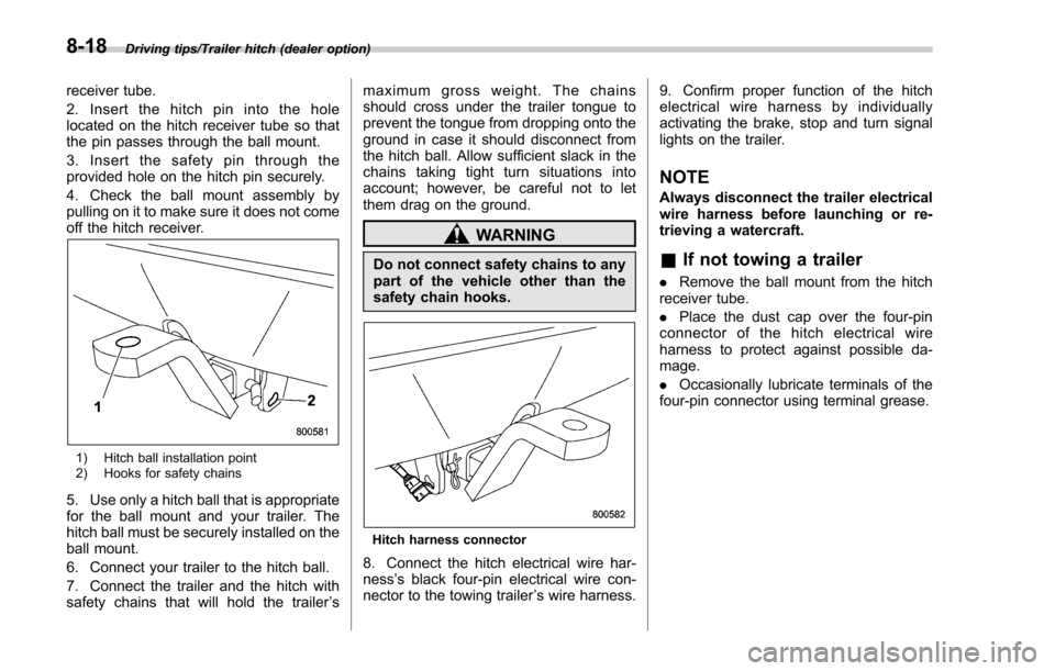
Driving tips/Trailer hitch (dealer option)
receiver tube.
2. Insert the hitch pin into the hole
located on the hitch receiver tube so that
the pin passes through the ball mount.
3. Insert the safety pin through the
provided hole on the hitch pin securely.
4. Check the ball mount assembly by
pulling on it to make sure it does not come
off the hitch receiver.
1) Hitch ball installation point
2) Hooks for safety chains
5. Use only a hitch ball that is appropriate
for the ball mount and your trailer. The
hitch ball must be securely installed on the
ball mount.
6. Connect your trailer to the hitch ball.
7. Connect the trailer and the hitch with
safety chains that will hold the trailer’s maximum gross weight. The chains
should cross under the trailer tongue to
prevent the tongue from dropping onto the
ground in case it should disconnect from
the hitch ball. Allow sufficient slack in the
chains taking tight turn situations into
account; however, be careful not to let
them drag on the ground.
WARNING
Do not connect safety chains to any
part of the vehicle other than the
safety chain hooks.
Hitch harness connector
8. Connect the hitch electrical wire har-
ness
’s black four-pin electrical wire con-
nector to the towing trailer ’s wire harness. 9. Confirm proper function of the hitch
electrical wire harness by individually
activating the brake, stop and turn signal
lights on the trailer.
NOTE
Always disconnect the trailer electrical
wire harness before launching or re-
trieving a watercraft.
&
If not towing a trailer
. Remove the ball mount from the hitch
receiver tube.
. Place the dust cap over the four-pin
connector of the hitch electrical wire
harness to protect against possible da-
mage.
. Occasionally lubricate terminals of the
four-pin connector using terminal grease.
8-18
Page 500 of 634

total, one to the right side and the other to
the left side trailer tongue. Pass the chains
crossing each other under the trailer
tongue to prevent the trailer from dropping
onto the ground in case the trailer tongue
should disconnect from the hitch ball.
Allow sufficient slack in the chains taking
tight turn situations into account; however,
be careful not to let them drag on the
ground.
!Side mirrors
After hitching a trailer to your vehicle,
check that the standard side mirrors
provide a good rearward field of view
without significant blind spots. If significant
blind spots occur with the vehicle’ s stan-
dard side mirrors, use towing mirrors that
conform with Federal, state/province and/
or other applicable regulations. !
Trailer lights
CAUTION
Direct splicing or other improper
connection of trailer lights may
damage your vehicle’ s electrical
system and cause a malfunction of
your vehicle ’s lighting system.
Connection of trailer lights to your vehi-
cle ’s electrical system requires modifica-
tions to the vehicle ’s lighting circuit to
increase its capacity and accommodate
wiring changes. To ensure the trailer lights
are connected properly, please consult
your SUBARU dealer. Check for proper
operation of the turn signals and the brake
lights each time you connect a trailer to
your vehicle.
! Tires
WARNING
Never tow a trailer when the tem-
porary spare tire is used. The tem-
porary spare tire is not designed to
sustain the towing load. Use of the
temporary spare tire when towing
can result in failure of the spare tire
and/or less stability of the vehicle.
Make sure that all the tires on your vehicle are properly inflated. Refer to
“Tires”F 12-
10.
Trailer tire condition, size, load rating and
proper inflation pressure should be in
accordance with the trailer manufacturer ’s
specifications. Also check federal, state,
province and/or other applicable regula-
tions.
In the event your vehicle gets a flat tire
when towing a trailer, ask a commercial
road service representative or profes-
sional to repair the flat tire.
If you carry a regular size spare tire in your
vehicle or trailer as a precaution against
getting a flat tire, be sure that the spare
tire is firmly secured.
& Trailer towing tips
CAUTION
. For models equipped with the
BSD (Blind Spot Detection) and
RCTA (Rear Cross Traffic Alert)
driving support systems, when
towing a trailer, press the BSD/
RCTA OFF switch to deactivate
the system. The system may not
operate properly due to the
blocked radar waves. For details
about the BSD/RCTA OFF switch,
Driving tips/Trailer towing
–CONTINUED –8-23