2017 Seat Leon SC sport mode
[x] Cancel search: sport modePage 171 of 332

Transport and practical equipment
Hook the net bag next to the load threshold
● Secure the short net hooks to the fastening
rin g
s
››› Fig. 182 1
› ›› . The bag zip should
be f ac
in
g upwards.
● Secure the straps in the bag hooks 2 .
R emo
v
ing the net bag
The hooked up net bag is taut ››› .
● Remove the hooks and the net bag straps
fr om the f
a
stening rings and from the bag
hooks.
● Store the net bag in the luggage compart-
ment. WARNING
To secure the elastic net bag on the fastening
ring s
it must be stretched out. Once hooked
up it is taut. If the net bag is hooked up or un-
hooked incorrectly the hooks could cause in-
juries.
● Always secure the net hooks properly so
that they
do not suddenly release from the
fastening rings when hooking or unhooking
them.
● On hooking or unhooking them, protect
your eye
s and face in case the hooks are re-
leased suddenly.
● Always hook up the net bag hooks in the
desc
ribed order. If a hook is unexpectedly re-
leased the risk of injury is increased. Luggage compartment variable floor
3 Applies to the model: LEON/LEON SC
Fig. 183
Luggage compartment: variable
floor Fig. 184
Luggage compartment: variable
floor Variable floor in the tilted position
When the
v
ari
able floor is tilted you can ac-
cess the spare wheel/anti-puncture kit area. ●
Lift the
variable floor using handle
››› Fig. 183 1 , pull it back and push the
b ac
k
rest of the rear seat until the movable
part of the floor is resting on it.
● Rest the floor on its housings ›››
Fig. 184
(arrows).
169Technical data
Advice
Operation
Emergencies
Safety
Page 174 of 332

Operation
Fig. 188
Leon ST: attachment points for the
roof r
ailings for the roof carrier system. The crossbars are the basis of a series of spe-
c
i
al
roof carrier systems. For safety reasons,
special fixtures must be used to safely trans-
port luggage, bicycles, skis, surf boards or
boats on the roof. Suitable accessories can
be acquired at SEAT dealerships.
Always secure the crossbars and the roof car-
rier system properly. Always take the assem-
bly instructions that come with the crossbars
and the roof carrier system in question into
account.
LEON model
The front and rear attachment points 1 and
2 are only visible when the doors are open
› ›
›
Fig. 187 A.
Leon SC model
The front and rear attachment points 1 are
on ly
visible when the doors are open. The rear attachment points
3 are marked on the
t op edg
e of
the glass with arrow heads
››› Fig. 187 B.
LEON ST model
The crossbars are assembled on the roof rail-
ings. The attachment points can be seen on
bottom of the roof railing ››› Fig. 188. WARNING
Incorrect attachment and use of the cross-
bar s
and the roof carrier system may cause
the whole system to detach from the roof and
cause an accident and injuries.
● Always take the manufacturer assembly in-
structions
into account.
● Use only crossbars and the roof carrier sys-
tem when they ar
e in perfect condition and
are properly secured.
● Secure the crossbars and the roof carrier
syst
em properly.
● Check threaded joints and attachments
travel
ling and if necessary tighten them after
you have travelled a short distance. When
making long trips, check the threaded joints
whenever you stop for a rest.
● Always fit the special roof carrier systems
correctly
for wheels, skis and surfboards, etc.
● Do not modify or repair the crossbars or
roof c
arrier system. Note
Always read the assembly instructions that
come w ith the c
rossbars and the roof carrier
system carefully and keep them in the vehi-
cle. Loading the roof carrier system
The load can only be secured if the crossbars
and the roof
c
arrier system are properly in-
stalled ››› .
Max imum authori
sed roof load
The maximum permissible roof load is 75 kg.
This figure comes from the combined weight
of the roof carrier, the cross bars and the load
itself on the roof ››› .
A lw
a
ys check the weight of the roof carrier
system, the cross bars and the weight of the
load to be transported and weigh them if
necessary. Never exceed the maximum au-
thorised roof load.
If you are using cross bars and a roof carrier
with a lower weight rating, you will not be
able to carry the maximum authorised roof
load. In this case, do not exceed the maxi-
mum weight limit for the roof carrier which is
listed in the fitting instructions.
172
Page 188 of 332

Operation
●
Dependin g on w
eather conditions, it may
become extremely hot or cold inside the vehi-
cle. This can be fatal. Brakes
New brake pads
For the fir
s
t 400 km (250 miles), new brake
pads have not yet reached their maximum
braking capacity, and need to be “run in”
first. However, you can compensate for the
slightly reduced braking effect by applying
more pressure on the brake pedal. Avoid
overloading the brakes while running them
in.
Wear
The rate of wear on the brake pads depends
a great deal on how you drive and the condi-
tions in which the vehicle is operated. This is
a particular problem in urban traffic and
short stretches, or with very sporty driving.
Depending on the speed, the braking force
and the environmental conditions (for exam-
ple, the temperature, air humidity, etc.)
noises may be produced on braking.
Wet roads or road salt
In certain situations (for example, on driving
through flooded areas, in severe downpours
or after washing the vehicle) the braking ac- tion could be delayed if the discs and pads
are d
amp
, or frozen in winter. In this case the
brakes should be “dried” by pressing the
brake pedal several times.
At high speed and with the windscreen wip-
ers activated, the brake pads will briefly
touch the brake discs. This takes place, al-
though unnoticeable to the driver, at regular
intervals to improve the response time of the
brakes when they are wet.
The effectiveness of the brakes can also be
temporarily reduced if the vehicle is driven
for some distance without using the brakes
when there is a lot of salt on the road in win-
ter. The layer of salt that accumulates on the
discs and pads can be removed by gently ap-
plying the brakes a few times.
Corrosion
There may be a tendency for corrosion to
form on the discs and dirt to build up on the
brake pads if the vehicle is used infrequently
or the brakes are not used very often.
If the brakes are not used frequently, or if
rust has formed on the disks, it is advisable
to clean off the pads and disks by braking
firmly a few times at a moderately high speed
››› .
F au
lt
in the brake system
If the brake pedal travel should ever increase
suddenly, this may mean that one of the two brake circuits has failed. Drive immediately
to the near
est specialised workshop and
have the fault repaired. Drive there slowly
and remember that you will have to apply
more pressure on the brake pedal and allow
for longer stopping distances.
Low brake fluid level
Malfunctions can occur in the brake system if
the brake fluid level is too low. The brake flu-
id level is monitored electronically.
Brake servo
The brake servo increases the pressure you
apply to the brake pedal. It works only when
the engine is running. WARNING
● App ly
the brakes heavily to clean the brake
system only in a suitable traffic situation. Do
not put other road users in danger: there is
risk of causing an accident.
● Ensure the vehicle does not move while in
neutral, when the en
gine is stopped. Failure
to follow this instruction could result in an
accident.
● If the brake fluid loses its viscosity and is
subj
ected to heavy use, vapour bubbles can
form in the brake system. This reduces the ef-
ficiency of the brakes. 186
Page 190 of 332
Operation
at a higher speed than the inner wheel. In
thi s
w
ay, the wheel that is turning faster (out-
er wheel) receives less drive torque than the
inner wheel. This may mean that in certain
situations the torque delivered to the inner
wheel is too high, causing the wheels to
spin. On the other hand, the outer wheel is
receiving a lower drive torque than it could
transmit. This causes an overall loss of lateral
grip on the front axle, resulting in understeer
or “lengthening” of the trajectory.
The XDS system can detect and correct this
effect via the sensors and signals of the ESC.
Via the ESC, the XDS will brake the inside
wheel and counter the excess driving torque
of that wheel. This means that the driver's
desired trajectory is much more precise.
The XDS system works in combination with
the ESC and is always active, even when ASR
traction control is disconnected, or the ESC in
Sport mode or disconnected.
Multi-collision Brake
In an accident, the multi-collision brake can
help the driver by braking to avoid the risk of
skidding during the accident, which could
lead to further collisions.
The multi-collision brake works for front, side
or rear accidents, when the airbag control
unit records its activation level and the acci-
dent takes place at a speed of over 10 km/h
(6 mph). The ESC automatically brakes the vehicle, as long as the accident has not dam-
aged the ESC, the br
ake hydraulics or the on-
board network
The following actions control automatic brak-
ing during the accident:
● When the driver presses the accelerator,
the automatic
braking does not take place.
● When the braking pressure through press-
ing the brak
e pedal is greater than the sys-
tem’s braking pressure the vehicle will brake
automatically.
● Multi-collision braking will not be available
if ESC
is malfunctioning. WARNING
● The ESC, ABS, ASR, EDL, el ectr
onic self-
locking differential or selective torque control
systems cannot exceed the limits imposed by
the laws of physics. Always bear this in mind,
especially on wet or slippery roads. If you no-
tice the systems cutting in, you should re-
duce your speed immediately to suit the road
and traffic conditions. Do not be encouraged
to take risks by the presence of more safety
systems. If you do, an accident may occur.
● Please remember that the accident risk al-
way
s increases if you drive fast, especially in
corners or on a slippery road, or if you follow
too close behind the vehicle in front of you.
The ESC, ABS, brake assist, EDL, electronic
self-locking and selective torque control sys-
tems cannot prevent accidents: risk of acci-
dents! ●
Ac c
elerate with caution on slippery surfa-
ces (for example, icy or snow-covered). De-
spite the control systems, the driven wheels
could spin, affecting the stability of the vehi-
cle: risk of accident! Note
● The ABS and ASR w i
ll only operate correctly
if the four wheels have identical tyres. Any
differences in the rolling radius of the tyres
can cause the system to reduce engine power
when this is not desired.
● The regulating processes of the systems
can mak
e noises when they intervene.
● If the warning lamp lights up
, or alter-
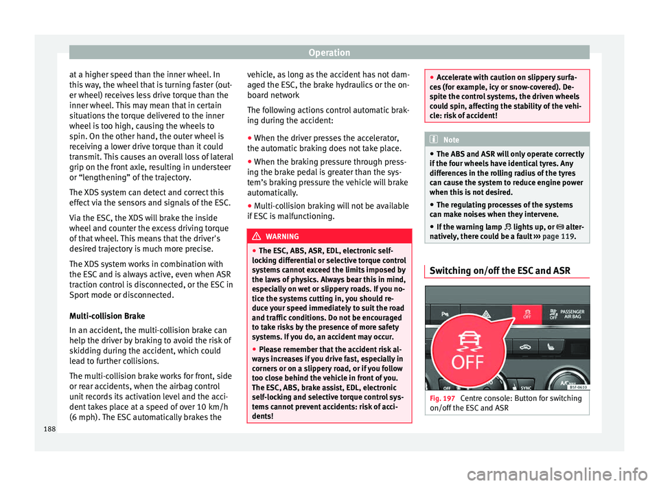
natively, there could be a fault ››› page 119. Switching on/off the ESC and ASR
Fig. 197
Centre console: Button for switching
on/off the E
SC
and ASR188
Page 191 of 332
Driving
The ESC is switched on automatically when
the en gine i
s
started, and only works when
the engine is running and includes the ABS,
EDS and ASR systems.
The ASR and ESC function should only be
switched off in situations in which traction is
insufficient, among others:
● When driving in deep snow or on surfaces
that ar
e not very firm.
● To “free” the vehicle if it gets stuck.
Then switc
h the ASR and ESC function back
on.
Depending on finishes and versions, it is
possible either to disconnect only the ASR or
else activate ESC Sport mode.
ESC in “Sport” mode
Sport mode can be connected via the Easy
Connect ››› page 120 system menu. In front-
wheel drive vehicles, the interventions by the
ESC and the ASR are limited. In four-wheel
drive vehicles, the interventions by the ESC
are limited and the ASR is switched off com-
pletely ››› .
The c ontr
o
l lamp lights up. For vehicles
with a driver information system*, the driver
will be shown the electronic stability
control (ESC) option: sport.
Warning! Limited stability. Disable ESC “Sport” mode
Through the Ea
sy Connect system menu
››› page 120. The warning lamp will switch
off. For vehicles with a driver information sys-
tem*, the driver will be shown the elec-
tronic stability control (ESC)
option: on.
Disable ASR
The Easy Connect system menu is used to
switch off the ASR ››› page 120. The traction
control system will be disabled.
The control lamp lights up. For vehicles
with a driver information system* the driver
will be informed that ASR is disabled.
Activate ASR
The Easy Connect system menu ››› page 120
is used to switch on the ASR. The traction
control system will be enabled.
The control lamp switches off. For vehicles
with a driver information system* the driver
will be informed that ASR is enabled.
Disconnection of the ESC
In some versions of the model, besides the
traction control system (ASR), the electronic
stability programme (ESC) can also be
switched off. ●
Pres s the button ››› Fig. 197 for approxi-
mately 1 second to switch to ESC Sport
mode.
● Press the button ›››
Fig. 197 for approxi-
mately 3 seconds to switch off the Electronic
Stability programme (ESC), including the ASR
function. The control lamp lights up and
the ESC OFF message is displayed perma-
nently on the instrument panel display.
● The ASR and ESC function are reconnected
by pr
essing the button ››› Fig. 197.
● OR: activate or deactivate the ESC Sport or
ESC
function in the Easy Connect system us-
ing the button and the
S
ET
TINGS and
E SC
System function buttons. The
contr
o l
lamp and the ESC OFF message on the in-
strument panel go out. WARNING
You should switch on the ESC Sport mode on-
ly if the tr
affic conditions and your driving
ability allow you to do so safely: risk of skid-
ding!
● With ESC in Sport mode, the stabilising
function w
ill be limited to allow for a sportier
drive. The driving wheels could spin and the
vehicle could “skid”.
● If the ESC is deactivated, the vehicle stabi-
lisation f
unction is not available. » 189
Technical data
Advice
Operation
Emergencies
Safety
Page 192 of 332

Operation
Note
● If the ASR i s
disconnected or the ESC’s
Sport mode is selected, cruise control* will
be switched off.
● In ESC OFF mode, the ESC w
ill be tempora-
rily reactivated to assist the driver during
braking and will then switch back to passive
mode when the brake pedal is released (de-
pending on the model version). Hill driving assistant
3 V
alid for vehicles: Without Auto Hold function
The hi
ll driving assistant helps the driver to
move off and upward on a hill when the vehi-
cle is stationary.
The system maintains brake pressure for ap-
proximately two seconds after the driver
takes his foot off the brake pedal to prevent
the vehicle from lurching backward when it is
started. During these 2 seconds, the driver
has enough time to release the clutch pedal
and accelerate without the vehicle moving
and without having to use the handbrake,
making start-up easier, more comfortable
and safer.
These are the basic operation conditions:
● being on a ramp or hill/slope,
● driver door closed,
● vehicle completely stationary, ●
engine ru nnin
g and foot on the brake,
● besides having a gear engaged or being in
neutral f
or manual gear change and with the
selector lever at position S, D or R for an au-
tomatic gearbox.
This system is also active when reversing up-
hill. WARNING
● If y
ou do not start the vehicle immediately
after taking your foot off the brake pedal, the
vehicle may start to roll back under certain
conditions. Depress the brake pedal or use
the hand brake immediately.
● If the engine stalls, depress the brake ped-
al or u
se the hand brake immediately.
● When following a line of traffic uphill, if you
want t
o prevent the vehicle from rolling back
accidentally when starting off, hold the brake
pedal down for a few seconds before starting
off. Note
The Official Service or a specialist workshop
can t el
l you if your vehicle is equipped with
this system. Manual gearbox
Ch an
gin
g gear Read the additional information carefully
›› ›
page 50
In some countries the clutch pedal must be
fully pressed down for the engine to start.
Selecting reverse gear ● Engage reverse gear only when the vehicle
is s
topped.
Changing down gears
While driving, changing down a gear must al-
ways be done gradually, i.e. to the gear di-
rectly below and when the engine speed is
not too high ››› . Changing down while by-
p a
s
sing one or various gears at high speeds
or at high engine speeds can damage the
clutch and the gearbox, even if the clutch
pedal remains depressed ››› .
WARNING
When the engine is running, the vehicle will
st ar
t to move as soon as a gear is engaged
and the clutch released. This is also the case
with the electronic parking brake switched
on.
● Never engage reverse gear when the vehi-
cle i
s moving. 190
Page 193 of 332

Driving
WARNING
If the gear is changed down inappropriately
by sel
ecting a gear that is too low, you may
lose control of the vehicle, causing an acci-
dent and serious injuries. CAUTION
When travelling at high speeds or at high en-
gine speed s, sel
ecting a gear that is too low
can cause considerable damage to the clutch
and the gearbox. This can also occur if the
clutch pedal is pressed and held and it does
not engage. CAUTION
To prevent damage and avoid premature
we ar
, please observe the following:
● Do not rest your hand on the gear lever
while driv
ing. The pressure applied by your
hand is transmitted to the gearbox selector
forks.
● Always ensure that the vehicle is complete-
ly st
opped before engaging the reverse gear.
● Always press the clutch to the floor when
chan
ging gears.
● Never hold the vehicle “on the clutch” on
hill
s with the engine on. Automatic gearbox/DSG auto-
m
atic
g
earbox*
Introduction Your vehicle is equipped with an electronical-
ly c
ontr
olled manual gearbox. Torque be-
tween the engine and the gearbox is trans-
mitted via two independent clutches. They re-
place the torque converter found on conven-
tional automatic gearboxes and allow for
smooth, uninterrupted acceleration of the ve-
hicle.
The tiptronic system allows the driver to
change gears manually if desired
››› page 193, Engaging gears with the trip-
tonic mode*.
Selector lever positions Read the additional information carefully
› ›
›
page 50
The selector lever position engaged is high-
lighted on the display in the instrument clus-
ter. With the selector lever in the manual
gearbox positions G, D, E and S, the engaged
gear is also indicated on the display.
P – Parking lock
When the selector lever is in this position,
the driven wheels are locked mechanically. The parking lock must be engaged only when
the vehic
le is stationary ››› .
The int erloc
k
button (the button on the selec-
tor lever handle) must be pressed in and si-
multaneously the brake pedal must be de-
pressed before moving the selector lever ei-
ther in or out of position P.
R – Reverse gear
Reverse gear must be engaged only when the
vehicle is stationary and the engine is idling
››› .
T o mo
v
e the selector lever to position R, the
interlock button must be pressed in and at
the same time the brake pedal must be de-
pressed. The reverse lights come on when
the selector lever is in the R position with the
ignition on.
N – Neutral (idling)
With the selector lever in this position, the
gear is in neutral.
D/S – Permanent drive (forward) position
The selector lever in the D/S position enables
the gears to be controlled in normal mode (D)
or Sport (S) mode. To select Sport mode (S),
move the selector lever backwards. Moving
the lever again will select normal mode (D).
The selected driving mode is shown on the
instrument panel display. »
191
Technical data
Advice
Operation
Emergencies
Safety
Page 194 of 332

Operation
In norm al mode
(D), the g
e arbox automatical-
ly selects the best gear ratio. This depends
on the engine load, the road speed and the
dynamic gear control programme (DCP).
Sport mode (S) must be selected for a sporty
driving style. This setting makes use of the
engine's maximum power output. When ac-
celerating the gear shifts will be noticeable.
Press the brake pedal to move the selector
lever from N to D/S when the vehicle is sta-
tionary or at speeds below 3 km/h (2 mph)
››› .
Under c er
t
ain circumstances (e.g. when driv-
ing in mountains) it can be advantageous to
switch temporarily to tiptronic mode
››› page 193, in order to manually select gear
ratios to suit the driving conditions. WARNING
● Tak e c
are not to accidentally press the ac-
celerator pedal when the vehicle is stopped.
The vehicle could otherwise start moving im-
mediately (in some cases even if the parking
brake is engaged) resulting in the risk of an
accident.
● Never move the selector lever to R or P
when driving. F
ailure to follow this instruc-
tion could result in an accident.
● With selector lever in any position (except
P) the vehic
le must always be held with the
foot brake when the engine is running. This is
because an automatic gearbox still transmits power even at idling speed, and the vehicle
tend
s
to “creep”. The accelerator pedal must
on no account be pressed inadvertently when
a gear is engaged with the vehicle stationary.
The vehicle could otherwise start moving im-
mediately (in some cases even if the parking
brake is engaged) resulting in the risk of an
accident.
● While you are selecting a gear and the vehi-
cle i
s stopped with the engine running, do
not accelerate. Failure to follow this instruc-
tion could result in an accident.
● As a driver you should never leave your ve-
hicle if
the engine is running and a gear is en-
gaged. If you have to leave your vehicle while
the engine is running, you must apply the
handbrake and engage the parking lock (P).
● To avoid accidents, apply the handbrake
and put the sel
ector lever in position P before
opening the bonnet and working on the vehi-
cle with the engine running. Please always
observe the important safety warnings
››› page 270, Working in the engine compart-
ment. Note
● If the sel ect
or lever is moved accidentally
to N when driving, release the accelerator and
let the engine speed drop to idling before se-
lecting gear range D or S again.
● Should the power supply to the selector
lever be int
errupted in position P, the selector
lever will be locked. If this should happen the
manual release can be used ›››
page 50. Selector lever lock
Fig. 198
Selector lever lock. The selector lever lock prevents gears from
bein g en
g
aged inadvertently, so that the ve-
hicle is not set in motion unintentionally.
The selector lever lock is released as follows:
– Switch the ignition on.
– Press the brake pedal and at
the same time
press in the interlock button.
Automatic selector lever lock
With the ignition switched on, the selector
lever is locked in the positions P and N. The
brake pedal must be pressed to release the
lever while pressing the release button if the
selector lever is in the position P. As a re-
minder for the driver, with the lever in posi-
tions P or N the following message will be
shown on the display:
192