2017 Seat Leon 5D radio
[x] Cancel search: radioPage 38 of 332

The essentials
Driver information System Intr oduction With the ignition switched on, it is possible
to r
e
ad the different functions of the display
by scrolling through the menus.
In vehicles with multifunction steering wheel,
the multifunction display can only be operat-
ed with the steering wheel buttons.
The number of menus displayed on the in-
strument panel will vary according to the ve-
hicle electronics and equipment.
A specialised workshop will be able to pro-
gramme or modify additional functions, ac-
cording to the vehicle equipment. SEAT rec-
ommends visiting a SEAT Official Service.
Some menu options can only be read when
the vehicle is at a standstill.
As long as a priority 1 warning is displayed, it
will not be possible to read the menus
››› page 41. Some warning messages can
be confirmed and made to disappear with the
windscreen wiper lever button or the multi-
function steering wheel button.
The information system also provides the fol-
lowing information and displays (depending
on the vehicle's equipment):
Driving data ›››
page 38
■ MFD from departure ■
MFD from r ef
uelling
■ MFD total calculation
Assist systems ››› page 40
Navigation ››› Booklet Navigation system
Audio ››› Booklet Radio or ››› Booklet Naviga-
tion system
Telephone ››› Booklet Radio or ››› Booklet
Navigation system
Vehicle status ››› page 41 WARNING
Any distraction may lead to an accident, with
the risk of
injury.
● Do not operate the instrument panel con-
trol
s when driving. Using the menus on the instrument
p
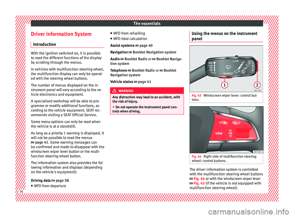
anel Fig. 43
Windscreen wiper lever: control but-
t on
s. Fig. 44
Right side of multifunction steering
wheel: c ontr
o
l buttons. The driver information system is controlled
w
ith the mu
ltif
unction steering wheel buttons
››› Fig. 44 or with the windscreen wiper lever
››› Fig. 43 (if the vehicle is not equipped with
multifunction steering wheel). 36
Page 40 of 332

The essentialsMenuFunction
Navigation
Information instructions from the acti-
vated navigation system: when a route
guidance is activated, the turning ar-
rows and proximity bars are displayed.
The appearance is similar to the Easy
Connect system.
If route guidance is not activated, the
direction of travel (compass) and the
name of the street along which you are
driving are shown
››› Booklet Naviga-
tion system.
Audio
Station display on the radio.
Track name on the CD.
Track name in Media mode ››› Booklet
Radio or ››› Booklet Navigation system.
Telephone
Information and possible configura-
tions of the mobile phone preinstalla-
tion ››› Booklet Radio or ››› Booklet Nav-
igation system.
Lap timer
In a racing circuit, measurement and
memorisation of lap times by the vehi-
cle and comparison with previously
measured best times ››› page 40.
Vehicle
statusDisplay of the current warning or infor-
mation texts and other system compo-
nents, according to equipment
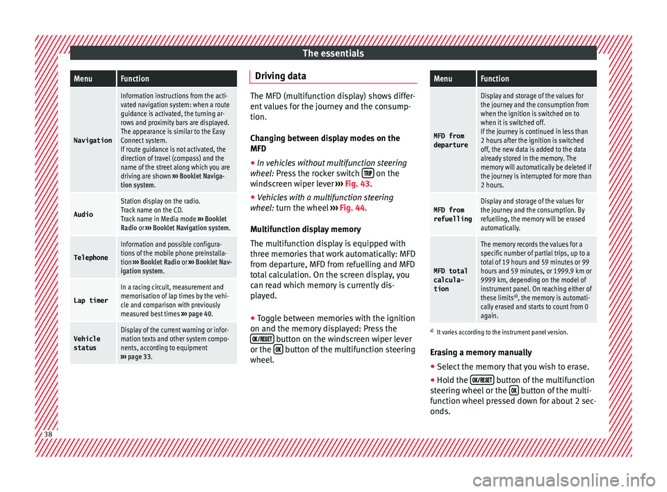
››› page 33. Driving data
The MFD (multifunction display) shows differ-
ent
v
alues for the journey and the consump-
tion.
Changing between display modes on the
MFD
● In vehicles without multifunction steering
wheel:
Press the rocker switch on the
wind s
creen wiper lever ››› Fig. 43.
● Vehicles with a multifunction steering
wheel:
turn the wheel ››› Fig. 44.
Multifunction display memory
The multifunction display is equipped with
three memories that work automatically: MFD
from departure, MFD from refuelling and MFD
total calculation. On the screen display, you
can read which memory is currently dis-
played.
● Toggle between memories with the ignition
on and the memory di
splayed: Press the
button on the windscreen wiper lever
or the button of the multifunction steering
wheel .
MenuFunction
MFD from
departure
Display and storage of the values for
the journey and the consumption from
when the ignition is switched on to
when it is switched off.
If the journey is continued in less than
2 hours after the ignition is switched
off, the new data is added to the data
already stored in the memory. The
memory will automatically be deleted if
the journey is interrupted for more than
2 hours.
MFD from refuellingDisplay and storage of the values for
the journey and the consumption. By
refuelling, the memory will be erased
automatically.
MFD total
calcula-
tion
The memory records the values for a
specific number of partial trips, up to a
total of 19 hours and 59 minutes or 99
hours and 59 minutes, or 1999.9 km or
9999 km, depending on the model of
instrument panel. On reaching either of
these limits a)
, the memory is automati-
cally erased and starts to count from 0
again.
a) It varies according to the instrument panel version.
Erasing a memory manually
● Select the memory that you wish to erase.
● Hold the button of the multifunction
s t
eerin
g wheel or the button of the multi-
f u nction wheel
pressed down for about 2 sec-
onds. 38
Page 45 of 332

The essentials
When the vehicle is at a standstill or when
tr av
el
ling at very low speeds, the tempera-
ture displayed may be higher than the true
outside temperature as a result of the heat
produced by the engine.
The temperatures measured range from
-40°C to +50°C (-40°F to +122°F).
Engine oil temperature display Vehicles without multifunction steering
wheel
● Press the rocker switch ›
››
Fig. 43 2 until
the m ain menu ap
pe
ars. Enter into Driving
data . With the button 2 move to the oil
t emper
at
ure gauge.
Vehicles with multifunction steering wheel
● Enter the submenu Driving data and
turn the thumbwheel
until the oil tempera-
ture display appears.
The engine reaches its operating temperature
when in normal driving conditions, the oil
temperature is between 80°C (180°F) and
120°C (250°F) . If the engine is required to
work hard and the outside temperature is
high, the engine oil temperature can in-
crease. This does not present any problem as
long as the warning lamps ›››
table on
page 48 or ››› table on page 48 do not
appear on the display. Additional consumers ●
Operation with the windscreen wiper lever*:
Pre s
s the rocker switch ››› Fig. 43 2 until the
main menu ap pe
ars. Enter into the section
Driving data . With the rocker switch,
move to the display Convenience con-
sumers .
● Operation with the multi-function steering
wheel*:
move with the buttons
or
to Driving data
and enter with
OK. Turn
the right thumbwheel until the Conven-
ience consumers display appears.
In addition, a scale will inform you of the cur-
rent sum of all the additional appliances.
Saving tips Tips on how to save fuel will be displayed in
c
ondition
s
that increase fuel consumption.
Follow them to reduce consumption. The indi-
cations appear automatically only with the ef-
ficiency programme. After a time, the tips will
disappear automatically.
If you wish to hide a saving tip immediately
after it appears, press any button on the
windscreen wiper lever*/multifunction steer-
ing wheel*. Note
● If y
ou hide a saving tip, it will reappear af-
ter you switch the ignition on again.
● The saving tips do not appear in all situa-
tions, but
rather with a large separation of
time. Speed warning device
The speed warning device warns the driver
when they h
av
e exceeded the pre-set speed
limit by 3 km/h (2 mph). An audible warning
signal sounds, and the warning lamp and
the driver message Speed limit excee-
ded! will be displayed simultaneously on the
instrument panel. The warning lamp
switches off when reducing speed below the
stored maximum limit.
Speed warning programming is recommen-
ded if you wish to be reminded of a maxi-
mum speed, such as when travelling in a
country with different speed limits or for a
maximum speed for winter tyres.
Setting speed limit warning
You can use the radio or the Easy Connect* to
set, alter or cancel the speed limit warning.
● Vehicles with radio : pres
s the button SETUP > control button Driver Assistant
>
Speed warning . » 43
Page 71 of 332

The essentials
● Ret
urn al
l tools to their proper storing loca-
tion.
● If the replaced wheel does not fit in the
spar
e wheel housing, store it safely in the
luggage compartment ›››
page 160.
● Check the tyre pressure of the newly moun-
ted tyr
e as soon as possible.
● In vehicles fitted with a tyre pressure indi-
cator
, adjust the pressure and store the read-
ing in the radio/Easy Connect system*
››› page 283.
● Have the tightening torque of the wheel
bolts c
hecked as soon as possible with a tor-
que wrench (it should be 120 Nm). Mean-
while, drive carefully.
● Have the flat tyre replaced as quickly as
poss
ible.
Snow chains Use Snow chains should only be used on the
fr
ont
wheel
s.
Check that they are correctly seated after
driving for a few yards; correct the position if
necessary, in accordance with the manufac-
turer's fitting instructions. Keep your speed
below 50 km/h (30 mph). If there is a danger of being trapped despite
havin
g mounted the chains, it is best to disa-
ble the driving wheels (ASR) in the ESC
››› page 188, Switching on/off the ESC
and ASR.
Snow chains will improve braking ability as
well as traction in winter conditions.
For technical reasons snow chains may only
be used with the following wheel rim/tyre
combination.
195/65 R15Chains with links of maximum 15 mm
205/55 R16Chains with links of maximum 15 mm
225/45 R17Chains with links of maximum 9 mm
225/40 R18Chains with links of maximum 9 mm Remove wheel covers and any integral trim
rin
g bef
or
e fitting snow chains.
Remove the chains when roads are free of
snow. Driving characteristics worsen, and the
wheels become damaged quickly and may
even be rendered unusable. Emergency towing of the vehi-
cle
T
owing Fig. 77
Right side of the front bumper: tow-
line anc hor
ag
e screwed in. Fig. 78
Right side of the rear bumper: towline
anc hor
ag
e screwed in. » 69
Page 104 of 332

Emergencies
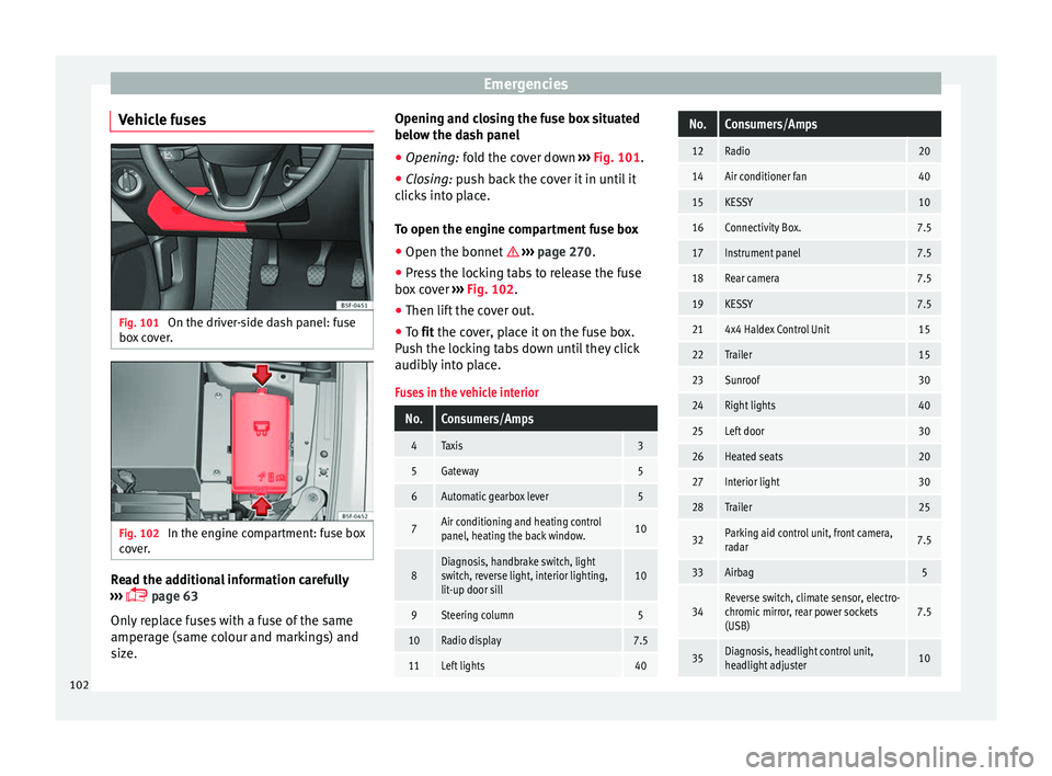
Vehicle fuses Fig. 101
On the driver-side dash panel: fuse
bo x
c
over. Fig. 102
In the engine compartment: fuse box
c o
v
er. Read the additional information carefully
› ›
›
page 63
Only replace fuses with a fuse of the same
amperage (same colour and markings) and
size. Opening and closing the fuse box situated
below the da
sh panel
● Opening: fold the cover down ››
› Fig. 101.
● Closing: push back the cover it in until it
clic
ks into place.
To open the engine compartment fuse box
● Open the bonnet ›››
page 270.
● Press the locking tabs to release the fuse
box c
over ››› Fig. 102.
● Then lift the cover out.
● To fit the cover, place it on the fuse box.
Pu
sh the locking tabs down until they click
audibly into place.
Fuses in the vehicle interior
No.Consumers/Amps
4Taxis3
5Gateway5
6Automatic gearbox lever5
7Air conditioning and heating control
panel, heating the back window.10
8Diagnosis, handbrake switch, light
switch, reverse light, interior lighting,
lit-up door sill10
9Steering column5
10Radio display7.5
11Left lights40
No.Consumers/Amps
12Radio20
14Air conditioner fan40
15KESSY10
16Connectivity Box.7.5
17Instrument panel7.5
18Rear camera7.5
19KESSY7.5
214x4 Haldex Control Unit15
22Trailer15
23Sunroof30
24Right lights40
25Left door30
26Heated seats20
27Interior light30
28Trailer25
32Parking aid control unit, front camera,
radar7.5
33Airbag5
34Reverse switch, climate sensor, electro-
chromic mirror, rear power sockets
(USB)7.5
35Diagnosis, headlight control unit,
headlight adjuster10 102
Page 115 of 332

Controls and displays
Operation
C ontr
o
ls and displays
General instrument panel Door release lever
Centr
al
locking switch . . . . . . . . . . . .128
Electric control to adjust exterior
mirrors . . . . . . . . . . . . . . . . . . . . . . . . . . . 151
Air outl
ets . . . . . . . . . . . . . . . . . . . . . . . . 176
Control lever for:
– Turn s ign
als and main beam
headlights . . . . . . . . . . . . . . . . . . . . . 141
– Lane Ass i
st . . . . . . . . . . . . . . . . . . . . . 224
– Main beam a
ssist . . . . . . . . . . . . . . . 142
– Cruise c
ontrol system (CCS) . . . . .209
Depending on equipment fitted:
– Lev er f
or cruise control . . . . . . . . . .209
Steering wheel with horn and – Driver airbag . . . . . . . . . . . . . . . . . . . 22
– On-boar d c
omputer controls . . . .36
– Contro
ls for radio, telephone,
navigation and speech dialogue
system ›››
Booklet Radio
– Paddle levers for tiptronic gear-
shift (automatic gearbox) . . . . . . .193
Instrument panel . . . . . . . . . . . . . . . . . 114
1 2
3
4
5
6
7
8 Control lever for:
– Wind
s
creen wipers and washer . .148
– Wipe and wa
sh system . . . . . . . . . . 148
– On-board c
omputer . . . . . . . . . . . . . 36
Depending on equipment fitted: ra-
dio or disp
lay for Easy Connect
(navigation, radio, TV/video) . . . . . .120
Depending on the equipment, but-
tons
for:
– SEAT driving modes . . . . . . . . . . . . .230
– Star t
-Stop system . . . . . . . . . . . . . . . 205
– Park a
ssist system . . . . . . . . . . . . . . 237
– Hazard w
arning lights . . . . . . . . . .145
– Tyr
e pressure switch . . . . . . . . . . . .285
– Airbag off di
splay . . . . . . . . . . . . . . . 89
Depending on the equipment,
glov e c
ompartment with: . . . . . . . . .158
– CD pl a
yer* and/or SD card*
››› Booklet Radio
Tyre pressure switch . . . . . . . . . . . . . .285
Front passenger airbag switch . . . .89
Front passenger airbag . . . . . . . . . . .22
Passenger seat heating control . . . .154
Depending on the equipment, con-
tro l
s for:
– Heating and ventilation system or
manual air conditioner . . . . . . . . . .56, 54
– Autom atic
air conditioner . . . . . . .52
9
10
11
12
13
14
15
16
17 Depending on the equipment:
– USB/A UX
-IN inp
ut . . . . . . . . . . . . . . 123
– Connectivity
Box/Wireless Charg-
er* . . . . . . . . . . . . . . . . . . . . . . . . . . . . . 123
– Storag
e compartment
Depending on equipment fitted,
gear lever or selector lever for:
– Manual gearbox . . . . . . . . . . . . . . . . 190
– Automatic
gearbox . . . . . . . . . . . . . 191
Electronic parking brake switch . . .183
Auto Hold switch . . . . . . . . . . . . . . . . . 208
Starter button (Keyless Access lock-
ing and ignition sys
tem) . . . . . . . . . . 180
Driver's seat heating control . . . . . .154
Ignition lock (vehicles without Key-
les
s Access) . . . . . . . . . . . . . . . . . . . . . . 178
Knee airbag . . . . . . . . . . . . . . . . . . . . . . 23
Adjustable steering column . . . . . . .21
Storage compartment
Bonnet lock
release . . . . . . . . . . . . . . . 271
Headlight range control . . . . . . . . . . .146
Headlight switch . . . . . . . . . . . . . . . . . 140
Electric windows . . . . . . . . . . . . . . . . . 136 Note
● Some of the equipment li
sted in this sec-
tion is only fitted on certain models or are op-
tional extras. » 18
19
20
21
22
23
24
25
26
27
28
29
30
31
113
Technical data
Advice
Operation
Emergencies
Safety
Page 116 of 332

Operation
●
A separ at
e Instructions Manual is enclosed
if the vehicle is equipped with a factory-fitted
radio, CD player, AUX IN connection or navi-
gation system. ●
The arran g
ement of switches and controls
on right-hand drive models* may be slightly
different from the layout shown in ›››
page 112. However, the symbols used to
identif y
the controls are the same. Instruments and warning/control lamps
Ins trument
s
View of instrument panel Fig. 122
Instrument panel, on dash panel. Details of the instruments
››
›
Fig. 122: Rev counter (with the engine ru nning, in
hundreds of revolutions per minute).
1 The beginning of the red zone of the rev
c
ou
nt
er indicates the maximum speed in
any gear after running-in and with the
114
Page 119 of 332

Instruments and warning/control lamps
Low consumption driving status (ECO)*
D ependin
g on the equipment, when driv
ing,
the “ECO ” display appears on the instrument
panel when the vehicle is in low consump-
tion status due to active cylinder manage-
ment (ACT ®
)* ››› page 200.
Identifying letters on engine (MKB)
Hold the button ››› Fig. 122 4 down for more
th an 15 sec
ond
s to display the vehicle's en-
gine code (MKB). To do this, the ignition
must be switched on and the engine switch-
ed off. WARNING
Observe the safety warnings ›››
in Warning
and contr o
l lamps on page 119. WARNING
Even though outside temperatures are above
freez in
g, some roads and bridges may be icy.
● At outside temperatures above +4°C
(+39°F), even when the “ice c
rystal” symbol
is not visible, there may still be patches of ice
on the road.
● The outside temperature sensor takes a
guideline meas
urement. Note
● Differ ent
versions of the instrument panel
are available and therefore the versions and instructions on the display may vary. In the
ca
se of
displays without warning or informa-
tion texts, faults are indicated exclusively by
the warning lamps.
● Depending on the equipment, some set-
tings
and instructions can also be carried out
in the Easy Connect system.
● When several warnings are active at the
same time, the symbol
s are shown succes-
sively for a few seconds and will stay on until
the fault is rectified. Odometer
Fig. 123
Instrument panel: odometer and re-
set b
utt
on. The distance covered is displayed in “kilome-
tr
e
s” or mi
les “m”. It is possible to change
the measurement units (kilometres
“km”/miles “m”) in the radio/Easy Connect*.
Please refer to the Easy Connect* Instructions
Manual for more details. Odometer/trip recorder
The odometer show
s the total distance cov-
ered by the vehicle.
The trip recorder shows the distance that has
been travelled since it was last reset. It is
used to measure short trips. The last digit of
the trip recorder indicates distances of 100
metres or tenths of a mile.
The trip recorder can be set to zero by press-
ing 0.0/SET
› ››
Fig. 123
.
F
ault display
If there is a fault in the instrument panel, the
letters DEF will appear in the trip recorder
display. Have the fault repaired immediately,
as far as is possible.
Coolant temperature gauge Fig. 124
Instrument panel: coolant tempera-
t ur
e g
auge » 117
Technical data
Advice
Operation
Emergencies
Safety