2017 SEAT IBIZA ST run flat
[x] Cancel search: run flatPage 48 of 248

The essentials
Repairing a tyre with the anti-punc-
t ur
e k
it Fig. 59
Standard representation: contents of
the anti-p u
nct
ure kit. The anti-puncture kit is located under the
floor p
anel
in the lug
gage compartment.
Sealing the tyre
● Unscrew the tyre valve cap and insert. Use
the ›››
Fig. 59 1 tool to remove the insert.
Pl ac
e it
on a clean surface.
● Shake the tyre sealant bottle vigorously
›››
Fig. 59 10 .
● Screw the inflator tube ››
›
Fig. 59 3 into
the se al
ant
bottle. The bottle's seal will break
automatically. ●
Remov
e the lid from the filling tube
››› Fig. 59 3 and screw the open end of the
t ube int
o the ty
re valve.
● With the tyre sealant bottle upside down,
fill
the tyre with the contents of the sealant
bottle.
● Remove the bottle from the valve.
● Place the insert back into the tyre valve us-
ing the too
l ››› Fig. 59 1 .
Infl atin
g the ty
re
● Screw the compressor tyre inflator tube
›››
Fig. 59 5 into the tyre valve.
● Check that the air bleed screw is closed
› ›
›
Fig. 59 7 .
● Start the engine and leave it running.
● Insert the connector ››
›
Fig. 59 9 into the
v ehic
l
e's 12-volt socket ›››
page 133.
● Turn the air compressor on with the ON/OFF
switc
h ››› Fig. 59 8 .
● Keep the air compressor running until it
r e
ac
hes 2.0 to 2.5 bar
(29-36 psi/200-250 kPa). A maximum of 8
minutes.
● Disconnect the air compressor.
● If it does not reach the pressure indicated,
uns
crew the tyre inflator tube from the valve.
● Move the vehicle 10m so that the sealant is
dis trib
uted throughout the tyre. ●
Scr ew the c
ompressor tyre inflator into the
valve.
● Repeat the inflation process.
● If the indicated pressure still cannot be
reac
hed, the tyre is too badly damaged. Stop
and request assistance from an authorised
technician.
● Disconnect the air compressor. Unscrew
the tyre infl
ator tube from the tyre valve.
● When the tyre pressure is between 2.5 and
2.0 bars, c
ontinue driving without exceeding
80 km/h (50 mph).
● Check the pressure again after 10 minutes
›››
page 78.
››› in TMS (Tyre Mobility System)* on
page 76
››› page 76 46
Page 55 of 248
The essentials
2. Connect one end of the re
d jump lead to
the positive + terminal of the vehicle
w ith the fl
at
battery A
› ››
Fig. 69
.
3.
Connect the other end of the red
jump
lead to the positive terminal + in the ve-
hic l
e pr
oviding assistance B .
4. For vehicles without Start-Stop system:
connect
one end of
the black jump lead to
the negative terminal – of the vehicle
pr o
v
iding the current B
› ››
Fig. 69
.
– F
or vehicles with Start-Stop system: con-
nect one end of
the black jump lead X to a
s uit
ab
le ground terminal, to a solid piece of
metal in the engine block, or to the engine
block itself ››› Fig. 70.
5. Connect the other end of the black
jump
lead X to a solid metal component bolted
t o the en
gine b
lock or to the engine block
itself of the vehicle with the flat battery.
Do not connect it to a point near the bat-
tery A .
6. Position the leads in such a way that they cannot
c
ome into contact with any moving
parts in the engine compartment.
Starting
7. Start the engine of the vehicle with the boostin
g battery and let it run at idling
speed. 8. Start the engine of the vehicle with the flat
batter
y and wait for 2 or 3 minutes until
the engine is running.
Removing the jump leads
9. Before you remove the jump leads, switch off the dipped be
am headlights if they are
switched on.
10.Turn on the heater blower and heated rear window in the
vehicle with the flat battery.
This helps minimise voltage peaks which
are generated when the leads are discon-
nected.
11.When the engine is running, disconnect the lea
ds in reverse order to the details
given above.
Make sure the battery clamps have sufficient
metal-to-metal contact with the battery termi-
nals.
If the engine fails to start, switch off the start-
er after about 10 seconds and try again after
about a minute. WARNING
● Ple a
se note the safety warnings referring to
working in the engine compartment
››› page 198, Working in the engine
compartment.
● The battery providing assistance must have
the same v
oltage as the flat battery (12 V)
and approximately the same capacity (see imprint on battery). Failure to comply could
re
s
ult in an explosion.
● Never use jump leads when one of the bat-
teries
is frozen. Danger of explosion! Even af-
ter the battery has thawed, battery acid could
leak and cause chemical burns. If a battery
freezes, it should be replaced.
● Keep sparks, flames and lighted cigarettes
awa
y from batteries, danger of explosion.
Failure to comply could result in an explo-
sion.
● Observe the instructions provided by the
manufact
urer of the jump leads.
● Do not connect the negative cable from the
other vehic
le directly to the negative terminal
of the flat battery. The gas emitted from the
battery could be ignited by sparks. Danger of
explosion.
● Do not attach the negative cable from the
other vehic
le to parts of the fuel system or to
the brake line.
● The non-insulated parts of the battery
clamp
s must not be allowed to touch. The
jump lead attached to the positive battery
terminal must not touch metal parts of the ve-
hicle, this can cause a short circuit.
● Position the leads in such a way that they
cannot c
ome into contact with any moving
parts in the engine compartment.
● Do not lean on the batteries. This could re-
sult
in chemical burns. » 53
Page 114 of 248
Operation
will initiate acoustic and optical warning sig-
n al
s
when your vehicle is tried to be forced.
The anti-theft alarm system is automatically
switched on when locking the vehicle. The
system is immediately activated and the turn
signal light located on the driver door will
flash along with the turn signals, indicating
that the alarm and the locking security sys-
tem (double lock) have been turned on.
If any of the doors or the bonnet are open,
they will not be included in the protection
zones of the vehicle when the alarm is con-
nected. If the door or the bonnet are subse-
quently closed, they will be automatically in-
cluded in the protection areas of the vehicle
and the turn signals will flash accordingly
when the doors close.
● The turn signal light will flash twice on
opening and deactiv
ating the alarm.
● The turn signal light will flash once on clos-
ing and activatin
g the alarm.
When does the system trigger an alarm?
The system triggers an alarm, if the following
unauthorised actions are carried out when
the vehicle is locked:
● Mechanical opening of the vehicle with the
vehicl
e key without switching on the ignition
in the next 15 seconds (in certain markets, such as the Netherlands, the alarm is activa-
ted immediat
ely).
● A door is opened.
● Opening the bonnet.
● The rear lid is opened.
● Ignition switched on with a non-validated
key.
● Mo
vements in the driving compartment
(vehicl
es with a volume sensor).
● Towing of the vehicle 1)
.
● Vehicle tilt angle 1)
.
● Undue manipulation of the alarm.
● Battery handling.
In this c
ase, the acoustic signals will go off
and the turn signal will flash for approximate-
ly 30 seconds. This cycle may be repeated up
to 10 times depending on the country.
Opening all the doors in manual mode
In vehicles without an alarm, when opening
the driver door manually, all doors are
opened.
How to switch the alarm off
To deactivate the anti-theft alarm, turn the
key in the opening direction, open the door and switch the ignition on, or press the un-
lock b
utton on the remote control.
In v
ehic
les equipped with an anti-theft alarm
system, you have 15 seconds to insert the
key in the ignition lock and activate the igni-
tion if the vehicle is opened using the driver
door key.
Otherwise, the alarm will trigger for 30 sec.
and the ignition will be blocked. Note
● Aft er 28 d
ays, the indicator light will be
switched off to prevent the battery from
draining if the vehicle has been left parked
for a long period of time. The alarm system
remains activated.
● The alarm will trigger again if attempts are
made t
o open another protection zone.
● The alarm system can be activated or deac-
tivated u
sing the radio frequency remote con-
trol ››› page 110.
● The anti-theft alarm is not activated when
the vehic
le is locked from within using the
central locking button .
● If the vehicle battery is run down or flat
then the anti-theft a
larm will not operate cor-
rectly.
● Vehicle monitoring remains active even if
the batter
y is disconnected or not working for
any reason. 1)
With vehicles fitted with a tow-away protection
112
Page 135 of 248
Transport and practical equipment
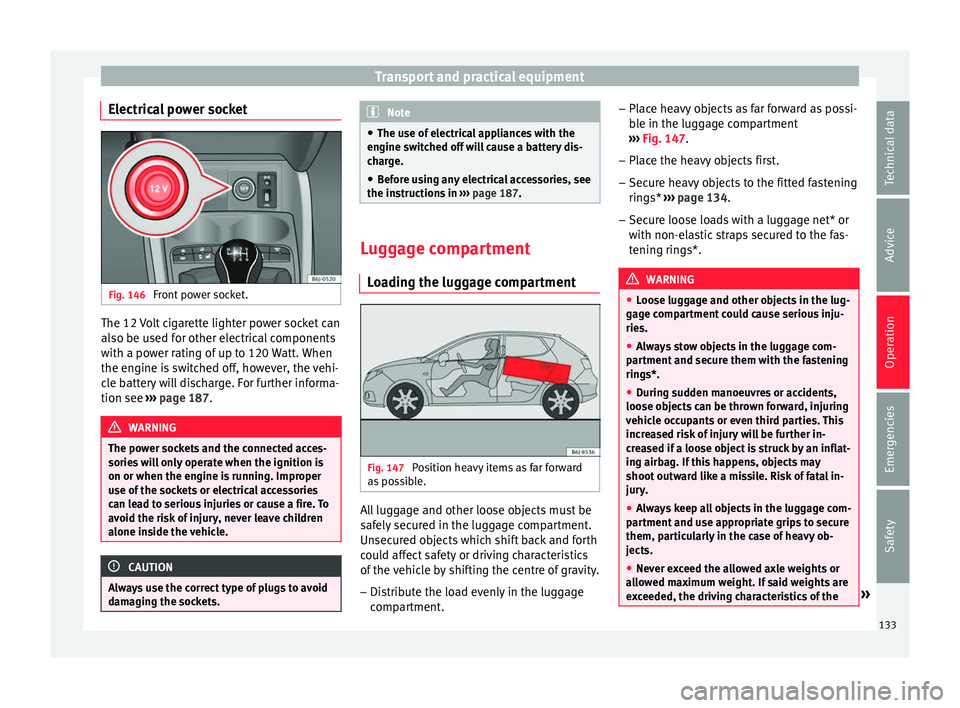
Electrical power socket Fig. 146
Front power socket. The 12 Volt cigarette lighter power socket can
al
so be u
sed f
or other electrical components
with a power rating of up to 120 Watt. When
the engine is switched off, however, the vehi-
cle battery will discharge. For further informa-
tion see ››› page 187. WARNING
The power sockets and the connected acces-
sories w
ill only operate when the ignition is
on or when the engine is running. Improper
use of the sockets or electrical accessories
can lead to serious injuries or cause a fire. To
avoid the risk of injury, never leave children
alone inside the vehicle. CAUTION
Always use the correct type of plugs to avoid
dam agin
g the sockets. Note
● The use of el
ectrical appliances with the
engine switched off will cause a battery dis-
charge.
● Before using any electrical accessories, see
the instruction
s in ››› page 187. Luggage compartment
Lo a
ding the luggage compartment Fig. 147
Position heavy items as far forward
a s
po
ssible. All luggage and other loose objects must be
s
af
ely
secured in the luggage compartment.
Unsecured objects which shift back and forth
could affect safety or driving characteristics
of the vehicle by shifting the centre of gravity.
– Distribute the load evenly in the luggage
compar
tment. –
Place he
avy objects as far forward as possi-
ble in the luggage compartment
››› Fig. 147.
– Place the heavy objects first.
– Secure heavy objects to the fitted fastening
rings* ›
›› page 134.
– Secure loose loads with a luggage net* or
with non-ela
stic straps secured to the fas-
tening rings*. WARNING
● Loo se lug
gage and other objects in the lug-
gage compartment could cause serious inju-
ries.
● Always stow objects in the luggage com-
partment
and secure them with the fastening
rings*.
● During sudden manoeuvres or accidents,
loose ob
jects can be thrown forward, injuring
vehicle occupants or even third parties. This
increased risk of injury will be further in-
creased if a loose object is struck by an inflat-
ing airbag. If this happens, objects may
shoot outward like a missile. Risk of fatal in-
jury.
● Always keep all objects in the luggage com-
partment
and use appropriate grips to secure
them, particularly in the case of heavy ob-
jects.
● Never exceed the allowed axle weights or
allo
wed maximum weight. If said weights are
exceeded, the driving characteristics of the » 133
Technical data
Advice
Operation
Emergencies
Safety
Page 136 of 248
Operation
vehicle may change, leading to accidents,
injuries
and d
amage to the vehicle.
● Please note that the centre of gravity may
shift when tr
ansporting heavy objects; this
may affect vehicle handling and lead to an ac-
cident. Therefore, it is essential to adjust
your speed and driving style accordingly, to
avoid accidents.
● Never leave your vehicle unattended, espe-
cia
lly when the rear lid is open. Children
could climb into the luggage compartment,
closing the door behind them; they will be
trapped and run the risk of death.
● Never allow children to play in or around
the vehic
le. Close and lock all the doors and
rear lid when you leave the vehicle. Before
you lock the vehicle, make sure that there are
no adults or children in the vehicle.
● Please observe the notes on the ›››
page 56. CAUTION
Hard objects on the rear shelf could chafe
again s
t the wires of the heating element in
the heated rear window and cause damage. Note
● The tyr e pr
essure must be adjusted accord-
ing to the load. When necessary check the
tyre pressures on the label located on the in-
side fuel tank flap ››› page 210.
● Air circulation in the vehicle helps reduce
foggin
g of the windows. Used air escapes through ventilation slits in the side trim of
the lugg
ag
e compartment. Ensure that the
ventilation slots are never covered.
● Straps for securing the load to the fasten-
ing ring
s* are commercially available from ac-
cessory shops. Fastening rings*
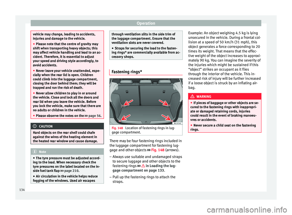
Fig. 148
Location of fastening rings in lug-
g ag
e c
ompartment. There may be four fastening rings included in
the lug
g
ag
e compartment for fastening lug-
gage and other objects ››› Fig. 148 (arrows).
– Always use suitable and undamaged straps
to secur
e luggage and other objects to the
fastening rings ››› in Loading the lug-
g ag
e c
ompartment on page 133.
– Pull up the fastening rings to attach the
strap
s. Example: An object weighing 4.5 kg is lying
unsec
ured in the vehicle. During a frontal col-
lision at a speed of 50 km/h (31 mph), this
object generates a force corresponding to 20
times its weight. That means that the effec-
tive weight of the object increases to approxi-
mately 90 kg. You can imagine the severity of
the injuries which might be sustained if this
“object” strikes an occupant as it flies
through the interior of the vehicle. This in-
creased risk of injury will be further increased
if a loose object is struck by an inflating air-
bag. WARNING
● If piec e
s of baggage or other objects are se-
cured to the fastening rings with inappropri-
ate or damaged retaining cords, injuries
could result in the event of braking manoeu-
vres or accidents.
● Never secure a child seat on the fastening
rings. 134
Page 168 of 248
Operation
the engine. Avoid running the engine at high
s peed.
P eriodic
maintenance
Periodic maintenance work guarantees that,
before beginning a journey, you will not con-
sume more than the required amount of fuel.
A well-serviced engine gives you the benefit
of improved fuel efficiency as well as maxi-
mum reliability and an enhanced resale val-
ue.
A badly serviced engine can consume up to
10% more fuel than necessary.
Avoid short journeys
To reduce the consumption and emission of
polluting exhaust gases, the engine and the
exhaust gas filtration systems should reach
the optimum operating temperature.
With the engine cold, fuel consumption is
proportionally higher. The engine does not
warm up and fuel consumption does not nor-
malise until having driven approximately four
kilometres (2.5 miles). This is why we recom-
mend avoiding short trips whenever possi-
ble.
Maintain the correct tyre pressures
Bear in mind that keeping the tyres at an ad-
equate pressure saves fuel. If the tyre pres-
sure is just one bar (14.5 psi/100 kPa) too
low, fuel consumption can increase by as much as 5%. Due to the greater rolling resist-
ance, under
-inflation also increases tyre wear
wear and impairs handling.
The tyre pressures should always be checked
when the tyres are cold.
Do not use winter tyres all year round as they
increase fuel consumption by up to 10%.
Avoid unnecessary weight
Given that every kilo of extra weight will in-
crease the fuel consumption, it is advisable
to always check the luggage compartment to
make sure that no unnecessary loads are be-
ing transported.
A roof rack is often left in place for the sake
of convenience, even when it is no longer
needed. At a speed of 100 km/h (62 mph)
and 120 km/h (75 mph) your vehicle will use
about 12% more fuel as a result of the extra
wind resistance caused by the roof rack even
when it is not in use.
Save electricity
The engine activates the alternator, which
produces electricity. With the need for elec-
tricity, fuel consumption also increases. Be-
cause of this, always turn off electrical devi-
ces when you do not need them. Examples of
devices that use a lot of electricity are: the
blower at high speeds, the rear window heat-
ing or the seat heaters*. Note
● If y
our vehicle has Start-Stop, it is not rec-
ommended that you switch this function off.
● It is recommended that you close
the win-
dows when driving at more than 60 km/h
(37 mph).
● Do not drive with your foot resting on the
clutc
h pedal,, as the pressure can make the
plate spin, more fuel will be used and it can
burn the clutch plate lining, causing a serious
fault.
● Do not hold the car on a hill with the clutch,
use the foot
brake or hand brake, using the
latter to start. The fuel consumption will be
lower and you will prevent the clutch plate
from being damaged.
● On descents, use the engine brake, chang-
ing to the g
ear that is more suitable for the
slope. Fuel consumption will be “zero” and
the brakes will not suffer. Engine management and ex-
h
au
s
t gas purification system
Introduction WARNING
● Bec au
se of the high temperatures which
can occur in the exhaust purification system
(catalytic converter or diesel particulate fil-
ter), do not park the vehicle where the 166
Page 210 of 248
Advice
WARNING
Always be aware of the danger of injury and
chemic a
l burns as well as the risk of accident
or fire when working on the battery and the
electrical system:
● Wear eye protection. Protect your eyes,
skin and clothin
g from acid and particles con-
taining lead.
● Battery acid is extremely corrosive. Wear
protectiv
e gloves and eye protection. Do not
tilt the batteries. This could spill acid through
the vents.
● Rinse battery acid from eyes immediately
for sever
al minutes with clear water. Then
seek medical care immediately. Neutralise
any acid splashes on the skin or clothing
with a soapy solution, and rinse off with plen-
ty of water. If acid is swallowed by mistake,
consult a doctor immediately.
● Fires, sparks, open flames and smoking are
prohibit
ed. When handling cables and electri-
cal equipment, avoid causing sparks and
electrostatic charge. Never short the battery
terminals. High-energy sparks can cause in-
jury.
● A highly explosive mixture of gases is re-
lea
sed when the battery is under charge. The
batteries should be charged in a well-ventila-
ted room only.
● Keep children away from acid and batteries.
● Before working on the electrical system,
you mus
t switch off the engine, the ignition
and all electrical devices. The negative cable on the battery must be disconnected. When a
light b
u
lb is changed, you need only switch
off the light.
● Deactivate the anti-theft alarm by unlock-
ing the v
ehicle before you disconnect the bat-
tery! The alarm will otherwise be triggered.
● When disconnecting the battery from the
vehicl
e on-board network, disconnect first
the negative cable and then the positive ca-
ble.
● Switch off all electrical devices before re-
connecting the b
attery. Reconnect first the
positive cable and then the negative cable.
Never reverse the polarity of the connections.
This could cause an electrical fire.
● Never charge a frozen battery, or one which
has
thawed. This could result in explosions
and chemical burns. Always replace a battery
which has frozen. A flat battery can also
freeze at temperatures close to 0°C (+32°F).
● Ensure that the vent hose is always connec-
ted to the b
attery.
● Never use a defective battery. This could
cause an e
xplosion. Replace a damaged bat-
tery immediately.
● For vehicles with the battery in the luggage
compar
tment: Check that the battery gas
ventilation hose is securely attached. CAUTION
● Never di s
connect the battery if the ignition
is switched on or if the engine is running. This could damage the electrical system or
electr
onic
components.
● Do not expose the battery to direct sunlight
over a lon
g period of time, as the intense ul-
traviolet radiation can damage the battery
housing.
● If the vehicle is left standing in cold condi-
tions f
or a long period, protect the battery
from “freezing”. If it freezes it will be dam-
aged. Warning lamp
It lights up
Alternator fault.
The control lamp
lights up when the igni-
tion i s
switched on. It should go out when the
engine has started running.
If the control lamp lights up while driving,
the alternator is no longer charging the bat-
tery. You should immediately drive to the
nearest specialised workshop.
You should avoid using electrical equipment
that is not absolutely necessary because this
will drain the battery.
208
Page 212 of 248
Advice
Wheels
Wheel s
and ty
res
General notes Avoiding damage
– If you have to drive over a kerb or similar
ob s
tacle, drive very slowly and at a right
angle.
– Keep grease, oil and fuel off the tyres.
– Inspect the tyres regularly for damage
(cuts, c r
acks or blisters, etc.). Remove any
foreign objects embedded in the treads.
Storing tyres
– When you remove the tyres, mark them in
order to m
aintain the same direction of ro-
tation when they are installed again.
– When removed, the wheels and/or tyres
should be s
tored in a cool, dry and prefera-
bly dark location.
– Store tyres in a vertical position, if they are
not fitted on wheel
rims.
New tyres
New tyres must be run in ›››
page 164.
The tread depth of new tyres may vary, ac-
cording to the type and make of tyre and the
tread pattern. Concealed damage
Damage t
o tyres and rims is often not readily
visible. If you notice unusual vibrations or the
vehicle pulling to one side, this may indicate
that one of the tyres is damaged. They
should be checked immediately by a Techni-
cal Service.
Tyres with directional tread pattern
An arrow on the tyre sidewall indicates the di-
rection of rotation on tyres with directional
tread. Always observe the direction of rota-
tion indicated when fitting the wheel. This
guarantees optimum grip and helps to avoid
aquaplaning, excessive noise and wear. WARNING
● New tyr e
s do not have maximum grip dur-
ing the first 500 km. Drive particularly care-
fully to avoid possible accidents.
● Never drive with damaged tyres. This may
cause an ac
cident.
● If you notice unusual vibrations or if the ve-
hicle p
ulls to one side when driving, stop the
vehicle immediately and check the tyres for
damage. Tyre pressure monitoring system
Fig. 176
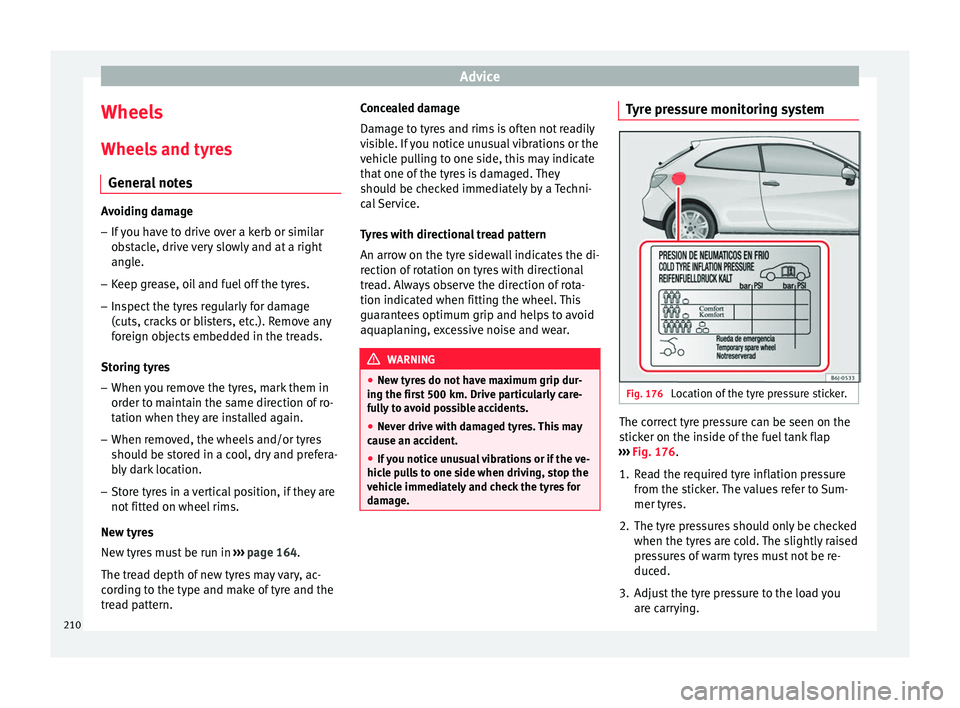
Location of the tyre pressure sticker. The correct tyre pressure can be seen on the
s
tic
k
er on the inside of the fuel tank flap
››› Fig. 176.
1. Read the required tyre inflation pressure from the stic
ker. The values refer to Sum-
mer tyres.
2. The tyre pressures should only be checked when the tyre
s are cold. The slightly raised
pressures of warm tyres must not be re-
duced.
3. Adjust the tyre pressure to the load you are carr
ying.
210