2017 RENAULT TRAFIC warning lights
[x] Cancel search: warning lightsPage 158 of 294

2.32
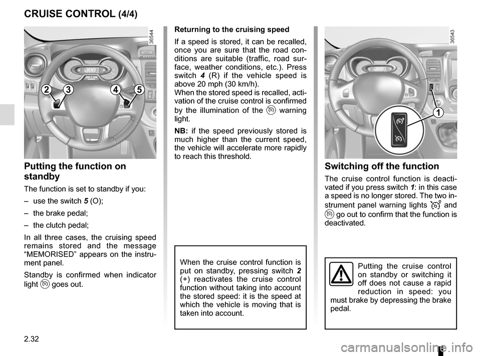
Switching off the function
The cruise control function is deacti-
vated if you press switch 1: in this case
a speed is no longer stored. The two in-
strument panel warning lights
and
go out to confirm that the function is
deactivated.
Returning to the cruising speed
If a speed is stored, it can be recalled,
once you are sure that the road con-
ditions are suitable (traffic, road sur-
face, weather conditions, etc.). Press
switch
4 (R) if the vehicle speed is
above 20 mph (30 km/h).
When the stored speed is recalled, acti-
vation of the cruise control is confirmed
by the illumination of the
warning
light.
NB: if the speed previously stored is
much higher than the current speed,
the vehicle will accelerate more rapidly
to reach this threshold.
When the cruise control function is
put on standby, pressing switch 2
(+) reactivates the cruise control
function without taking into account
the stored speed: it is the speed at
which the vehicle is moving that is
taken into account.
Putting the function on
standby
The function is set to standby if you:
– use the switch 5 (O);
– the brake pedal;
– the clutch pedal;
In all three cases, the cruising speed
remains stored and the message
“MEMORISED” appears on the instru-
ment panel.
Standby is confirmed when indicator
light
goes out.
CRUISE CONTROL (4/4)
Putting the cruise control
on standby or switching it
off does not cause a rapid
reduction in speed: you
must brake by depressing the brake
pedal.
2354
1
Page 162 of 294

2.36
Temporary deactivation of
the system
Press switch 2 to deactivate the system.
The indicator light built into the switch
lights up to remind you that the system
is deactivated.
Pressing the switch again will reacti-
vate the system and switch off the in-
dicator light.
Depending on the vehicle, you can de-
activate the parking distance control
from the touch-screen. Please see the
equipment instructions for further infor-
mation.
PARKING DISTANCE CONTROL (2/2)
Adjusting the parking
distance control volume
Depending on the vehicle, certain set-
tings can be adjusted from the touch-
screen 1. Please see the equipment in-
structions for further information.
The system is automatically reactivated
after the ignition is switched off and the
engine restarted.
Prolonged deactivation of the
system
You can deactivate the system perma-
nently by pressing and holding switch 2.
The warning light built into the switch
remains lit constantly.
The deactivated system can be re-
activated by pressing and holding the
switch again.
Operating faults
Depending on the vehicle, when the
system detects an operating fault, the
message “check parking distance con-
trol” appears on the instrument panel,
accompanied by the warning light
© and a beep lasting approxi-
mately 5 seconds. Please contact an
authorised dealer.
2
1
Page 227 of 294

5.5
TYRE PRESSURE KIT (2/3)
Before using this kit, park
the vehicle at a sufficient
distance from traffic, switch
on the hazard warning
lights, apply the handbrake, ask all
passengers to leave the vehicle and
keep them away from traffic.
Nothing should be placed
around the driver’s feet
as such objects may slide
under the pedals during
sudden braking manoeuvres and
obstruct their use.
Please be aware that a
poorly tightened or miss-
ing valve cap can make the
tyres less airtight and may
lead to pressure loss.
Always use valve caps identical to
those fitted originally and tighten
them fully.
If the vehicle is parked on
the hard shoulder, you must
warn other road users of
your vehicle’s presence
with a warning triangle or with other
devices as per the legislation apply-
ing to the country you are in.
Following repair with the kit,
do not travel further than
120 miles (200 km). In addi-
tion, reduce your speed and
under no circumstances exceed
48 mph (80 km/h). The sticker,
which you must affix in a prominent
position on the dashboard, reminds
you of this.
Depending on the country or local
legislation, a tyre repaired with the
inflation kit may need to be replaced.
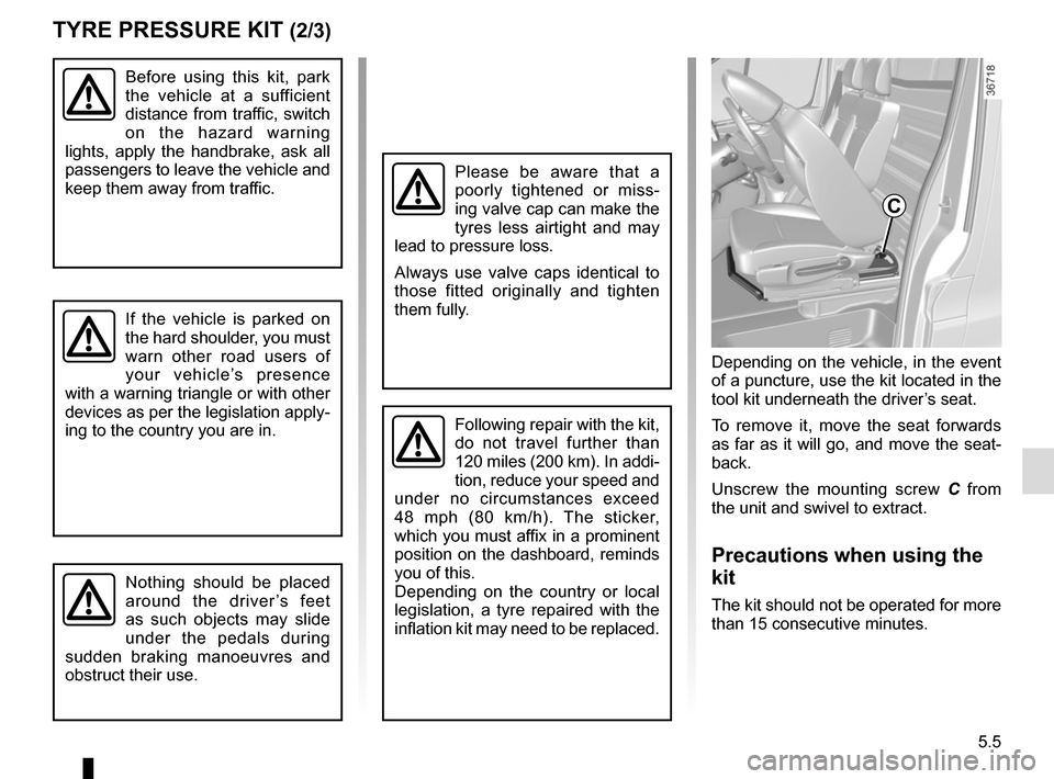
Depending on the vehicle, in the event
of a puncture, use the kit located in the
tool kit underneath the driver’s seat.
To remove it, move the seat forwards
as far as it will go, and move the seat-
back.
Unscrew the mounting screw C from
the unit and swivel to extract.
Precautions when using the
kit
The kit should not be operated for more
than 15 consecutive minutes.
C
Page 231 of 294

5.9
CHANGING A WHEEL (1/2)
Switch on the hazard warn-
ing lights.
Keep the vehicle away from
traffic and on a level surface
where it will not slip.
Apply the hand brake and engage a
gear (first or reverse, or P for auto-
matic transmissions).
Ask all the passengers to leave the
vehicle and keep them away from
traffic.
If the vehicle is parked on
the hard shoulder, you must
warn other road users of
your vehicle’s presence
with a warning triangle or with other
devices as per the legislation apply-
ing to the country you are in.
If you have a puncture, re-
place the wheel as soon as
possible.
A tyre which has been punc-
tured should always be inspected
(and repaired, where possible) by a
specialist.
Do not leave the tools un-
secured inside the vehicle
as they may come loose
under braking. After use,
check that all the tools are correctly
clipped into the tool kit, then position
it correctly in its housing: there is a
risk of injury.
The jack is designed for wheel
changing purposes only. Under no
circumstances should it be used for
carrying out repairs underneath the
vehicle or to gain access to the un-
derside of the vehicle.
Page 236 of 294

5.14
FRONT HEADLIGHTS: changing bulbs (1/2)
Take care when working in
the engine compartment
as the engine cooling fan
may start to operate at any
moment without warning.
Risk of injury.
Main headlight and dipped
beam headlight
Turn the cover B a quarter turn.
Disconnect the wiring 2.
Unclip spring 1 and remove the bulb.
Bulb type: H4.
Do not touch the bulb glass. Hold it
by its base.
Replace the bulb, replace the connec-
tors and check that the cover B is re-
placed correctly.
B
A
2
1Any operation on (or modi-
fication to) the electrical
system must be performed
by an approved dealer
since an incorrect connection might
damage the electrical equipment
(harness, components and in partic-
ular the alternator). In addition, your
Dealer has all the parts required for
fitting these units.
The bulbs are under pres-
sure and can break when
replaced.
Risk of injury.
The engine must be
stopped before any action
(and not on standby): stop
the engine (please refer
to the information on “Starting and
stopping the engine” in Section 2).
Daytime running lights
Turn the bulb holder A a quarter of a
turn and remove.
Bulb type: W21W/5W.
Change the bulb and replace the bulb
holder.
Page 251 of 294

5.29
No.Allocation
1 APC load for vehicle with
RENAULT card
2 Adjustment
3 Adjustment
4 + battery for vehicles with
RENAULT card
5 Additional heating and air
conditioning
6 Supplementary passenger
compartment heating
7 Electric door mirrors,
supplementary central unit
adjustment
8 Heated door mirror
9 Radio, multimedia, rear-view
mirror, diagnostic socket
10 Pre-equipment, towbar socket
11 Timed battery, passenger
compartment unit
12 Right-hand daytime running
light, front side lights, right-hand
main beam headlight, left-hand
dipped beam headlight
13 Hazard warning lights, direction
indicator lights
FUSES (3/3)
No.
Allocation
14 Central locking of opening
elements
15 Left-hand daytime running light,
rear side light, left-hand main
beam headlight, right-hand
dipped beam headlight
16 Registration plate lighting, front
and rear fog lights
17 Alarm, horn, lighting and wiper
stalks
18 Instrument panel
19 Heater
20 Rear screen wiper, screenwash
pump, horn
21 General APC load
22 Reversing lights
23 Brake switch
24 Injection, starting
25 Airbag, steering column lock
26 Passenger side window control
27 Power-assisted steering
28 Brake lightsNo. Allocation
29 APC load for vehicle with
RENAULT card
30 General service
31 Cigarette lighter, accessories
socket
32 Heater
33 Brake light, ABS, transponder
34 Interior lighting, air-conditioning
35 Starting for vehicles with
RENAULT card
36 Rear windscreen wiper
37 Electromagnetic notification
38 Accessories socket in the
loading area
39 Driver’s side window control
motor
40 Rear accessories socket
41 BCM starting
42 Heated seats
43 Tachograph
44 Front windscreen wiper
45 Heating, air conditioning system
Page 255 of 294

5.33
TOWING: breakdown recovery (1/2)
The steering wheel must be un-
locked and the ignition key must be
in position M (ignition on) to provide
brake lights and hazard warning
lights on the towed vehicle. At night
the vehicle must have its lights on.
Unhitch the trailer, etc., if one is
being towed.
You must observe the towing regu-
lations which apply in the country in
which you are driving: do not exceed
the towing weight for your vehicle.
Contact an approved dealer.
Never use the drive shafts or axles.
These towing points may only be used
for traction: never use them for lifting
the vehicle directly or indirectly.– Use a rigid towing bar.
If a rope or cable is used
(where the law allows this),
the vehicle being towed
must be able to brake.
– A vehicle must not be towed if it is
not fit to be driven.
– Do not accelerate or brake sud- denly when towing, as this may
result in damage being caused to
the vehicle.
– When towing a vehicle, do not exceed 15 mph (25 km/h).
– Do not push the vehicle if the steering column is locked.
When the engine is
stopped, steering and brak-
ing assistance are not op-
erational.
Do not remove the key from
the ignition switch or the
card from the reader during
towing.
Page 288 of 294

7.2
ALPHABETICAL INDEX (2/5)
driving positionsettings ............................................................1.32 → 1.36
driving recommendations ......................................2.12 → 2.15
E
ECO driving ...........................................................2.12 → 2.15
ECO mode ................................................................ 2.13, 3.10
electric beam height adjustment ......................... 1.107 – 1.108
electric windows ..................................................... 3.15 – 3.16
electronic stability control: ESC .............................2.21 → 2.25
emergency brake assist.........................................2.21 → 2.25
emergency braking ................................................2.21 → 2.25
emergency key ........................................................... 1.7 – 1.8
emergency spare wheel ............................................. 5.2 – 5.3
engine technical specifications .................................................. 6.8
engine coolant ..................................................................... 4.7
engine oil ...................................................................4.4 → 4.6
engine oil capacity ...................................................... 4.5 – 4.6
engine oil level ...........................................................4.4 → 4.6
engine specifications .................................................... 6.3, 6.8
engine standby ..........................................................2.7 → 2.9
engine start/stop button .............................................2.3 → 2.6
environment ............................................................\
........... 2.17
ESC: electronic stability control ....................1.86, 2.21 → 2.25
external temperature ....................................................... 1.100
F
faults operating faults ................................................5.35 → 5.41
filter air filter ........................................................................\
... 4.9
oil filter .................................................................. 4.5 – 4.6
passenger compartment filter ........................................ 4.9
fitting a radio ...................................................................... 5.26
fittings ...............................................................\
.....3.20 → 3.28front passenger air bag deactivation ................................. 1.77
front seat adjustment .............................................. 1.29 – 1.30
front seats adjustment ............................................... 1.28 – 1.30, 1.32
fuel advice on fuel economy ...................................2.12 → 2.15
consumption ....................................................2.12 → 2.15
filling .................................................... 1.84, 1.113 → 1.115
grade ............................................................ 1.113 → 1.115
fuel consumption ...................................................2.12 → 2.15
fuel filler cap ...................................................... 1.113 → 1.115
fuel level ................................................................1.84 → 1.88
fuel tank capacity ...............................................................\
....... 1.113
fuel tank capacity ............................................... 1.113 → 1.115
fuses ..................................................................\
....5.27 → 5.29
G
gear lever........................................................................\
... 2.11
grip control ........................................................................\
. 2.24
H
handbrake........................................................................\
.. 2.11
hazard warning lights signal ............................................ 1.109
headlight beam adjustment ................................ 1.107 – 1.108
headrest.................................................................... 1.28, 3.31
heated seats ...................................................................... 1.29
heated windscreen .................................................. 3.8 → 3.11
heating and air conditioning system ...............3.4 → 3.12, 3.14
heating system ........................................................3.4 → 3.13
Hill Start Assist.......................................................2.21 → 2.25
horn ...................................................................\
.............. 1.109
horn: flash ..................................................................\
......... 1.109
hubcap tool ................................................................. 5.7 – 5.8