2017 RENAULT TRAFIC tow
[x] Cancel search: towPage 205 of 294

3.41
TRANSPORTING OBJECTS towbar
Fitting the towbar coupling
ball
Position the ball within the range of
bolts 1 or 2 , to respect the height B,
which must be between 350 and
420 mm, with the vehicle laden (use the
illustration example below).
To assemble the towbar ball, please
consult the equipment assembly in-
structions.
A
If the towbar ball obscures the regis-
tration plate or the rear fog lights, it
should be removed when not in use.
In all cases, comply with local leg-
islation.
Permissible nose weight, maxi-
mum permissible towing weight,
braked and unbraked: refer to the
information on “Weights” in Section
6.
Choice and fitting of towing
equipment
Maximum weight of towing equip-
ment: 22 kg
To assemble the towbar ball, please
consult the equipment assembly in-
structions.
Please keep these instructions with
the rest of the vehicle documenta-
tion.
2
B
11
Fitting towing equipment
A: 1,090 mm
Page 217 of 294

4.11
TYRE PRESSURE (2/2)
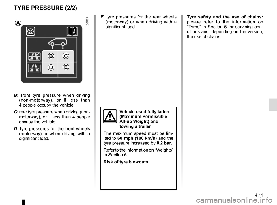
C
DE
B
A
B: front tyre pressure when driving
(non-motorway), or if less than
4 people occupy the vehicle.
C: rear tyre pressure when driving (non- motorway), or if less than 4 people
occupy the vehicle.
D : tyre pressures for the front wheels
(motorway) or when driving with a
significant load. E
: tyre pressures for the rear wheels
(motorway) or when driving with a
significant load.
Vehicle used fully laden
(Maximum Permissible
All-up Weight) and
towing a trailer
The maximum speed must be lim-
ited to 60 mph (100 km/h) and the
tyre pressure increased by 0.2 bar.
Refer to the information on “Weights”
in Section 6.
Risk of tyre blowouts.
Tyre safety and the use of chains:
please refer to the information on
“Tyres” in Section 5 for servicing con-
ditions and, depending on the version,
the use of chains.
Page 223 of 294

5.1
Section 5: Practical advice
Puncture, emergency spare wheel . . . . . . . . . . . . . . . . . . . . . . . . . . . . . . . . . . . .\
. . . . . . . . . . . . . . 5.2
Tyre inflation kit . . . . . . . . . . . . . . . . . . . . . . . . . . . . . . . . . . . .\
. . . . . . . . . . . . . . . . . . . . . . . . . . . . . 5.4
Tools . . . . . . . . . . . . . . . . . . . . . . . . . . . . . . . . . . . .\
. . . . . . . . . . . . . . . . . . . . . . . . . . . . . . . . . . . . . 5.7
Wheel trims . . . . . . . . . . . . . . . . . . . . . . . . . . . . . . \
. . . . . . . . . . . . . . . . . . . . . . . . . . . . . . . . . . . . . . 5.8
Changing a wheel . . . . . . . . . . . . . . . . . . . . . . . . . . . . . . . . . . . .\
. . . . . . . . . . . . . . . . . . . . . . . . . . . 5.9
Tyres (tyre and wheel safety, use in winter) . . . . . . . . . . . . . . . . . . . . . . . . . . . . . . . . . . . .\
. . . . . . . 5.11
Headlights (changing bulbs) . . . . . . . . . . . . . . . . . . . . . . . . . . . . . . . . . . . .\
. . . . . . . . . . . . . . . . . . . 5.14
Side lights . . . . . . . . . . . . . . . . . . . . . . . . . . . . . . . . . . . .\
. . . . . . . . . . . . . . . . . . . . . . . . . . . . . . . . . 5.15
Rear lights (changing bulbs) . . . . . . . . . . . . . . . . . . . . . . . . . . . . . . . . . . . .\
. . . . . . . . . . . . . . . . . . . 5.16
Indicator lights (changing bulbs) . . . . . . . . . . . . . . . . . . . . . . . . . . . . . . . . . . . .\
. . . . . . . . . . . . . . . . 5.19
Interior lighting (changing bulbs) . . . . . . . . . . . . . . . . . . . . . . . . . . . . . . . . . . . . \
. . . . . . . . . . . . . . . . 5.20
Key, radio frequency remote control: battery . . . . . . . . . . . . . . . . . . . . . . . . . . . . . . . . . . . . \
. . . . . . . 5.22
RENAULT card: battery . . . . . . . . . . . . . . . . . . . . . . . . . . . . . . . . . . . . \
. . . . . . . . . . . . . . . . . . . . . . . 5.23
Battery . . . . . . . . . . . . . . . . . . . . . . . . . . . . . . . . . . . . \
. . . . . . . . . . . . . . . . . . . . . . . . . . . . . . . . . . . . 5.24
Fitting a radio . . . . . . . . . . . . . . . . . . . . . . . . . . . . . . . . . . . . \
. . . . . . . . . . . . . . . . . . . . . . . . . . . . . . . 5.26
Fuses . . . . . . . . . . . . . . . . . . . . . . . . . . . . . . . . . . . . \
. . . . . . . . . . . . . . . . . . . . . . . . . . . . . . . . . . . . . 5.27
Accessories . . . . . . . . . . . . . . . . . . . . . . . . . . . . . . . . . . . . \
. . . . . . . . . . . . . . . . . . . . . . . . . . . . . . . . 5.30
Wipers (replacing blades) . . . . . . . . . . . . . . . . . . . . . . . . . . . . . . . . . . . .\
. . . . . . . . . . . . . . . . . . . . . 5.31
Towing . . . . . . . . . . . . . . . . . . . . . . . . . . . . . . . . . . . . \
. . . . . . . . . . . . . . . . . . . . . . . . . . . . . . . . . . . . 5.33
Operating faults . . . . . . . . . . . . . . . . . . . . . . . . . . . . . . . . . . . . \
. . . . . . . . . . . . . . . . . . . . . . . . . . . . . 5.35
Page 225 of 294

5.3
To refit emergency spare wheel B
Proceed in reverse order. Check that
wheel carrier 4 is correctly positioned
before tightening nuts 3 and 5.
PUNCTURE, EMERGENCY SPARE WHEEL (2/2)
Emergency spare wheel
On equipped vehicles, use tool A,
comprising:
– wheelbrace 2;
– for some versions, special end piece 1 (which must be added).
These components are stored in the
tool kit. To take out emergency spare wheel B
Using the tool A
, completely unscrew
the nut 5 (right-hand side) and partially
unscrew the nut 3 (left-hand side) until
the notch of the wheel carrier 4 is re-
leased from the nut 3.
Move it up and down and from side to
side to release the emergency spare
wheel.
Depending on the vehicle, a note in the
tool kit covers these instructions.
In some cases (rear puncture, vehi-
cle loaded with towing equipment,
etc.), it is necessary to raise the
vehicle (using the lifting point near-
est the wheel concerned) to permit
access to the emergency spare
wheel.
A
4
3
B
5
1
2
2
Page 229 of 294

5.7
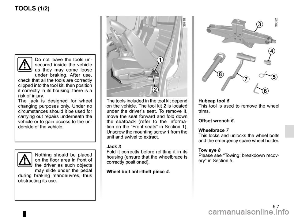
The tools included in the tool kit depend
on the vehicle. The tool kit 2 is located
under the driver’s seat. To remove it,
move the seat forward and fold down
the seatback (refer to the informa-
tion on the “Front seats” in Section 1).
Unscrew the mounting screw 1 from the
unit and swivel to extract.
Jack 3
Fold it correctly before refitting it in its
housing (ensure that the wheelbrace is
correctly positioned).
Wheel bolt anti-theft piece 4.
TOOLS (1/2)
Hubcap tool 5
This tool is used to remove the wheel
trims.
Offset wrench 6.
Wheelbrace 7
This locks and unlocks the wheel bolts
and the emergency spare wheel holder.
Tow eye 8
Please see “Towing: breakdown recov-
ery” in Section 5.
3
4
Do not leave the tools un-
secured inside the vehicle
as they may come loose
under braking. After use,
check that all the tools are correctly
clipped into the tool kit, then position
it correctly in its housing: there is a
risk of injury.
The jack is designed for wheel
changing purposes only. Under no
circumstances should it be used for
carrying out repairs underneath the
vehicle or to gain access to the un-
derside of the vehicle.
Nothing should be placed
on the floor area in front of
the driver as such objects
may slide under the pedal
during braking manoeuvres, thus
obstructing its use.
2
5
6
78
1
Page 251 of 294

5.29
No.Allocation
1 APC load for vehicle with
RENAULT card
2 Adjustment
3 Adjustment
4 + battery for vehicles with
RENAULT card
5 Additional heating and air
conditioning
6 Supplementary passenger
compartment heating
7 Electric door mirrors,
supplementary central unit
adjustment
8 Heated door mirror
9 Radio, multimedia, rear-view
mirror, diagnostic socket
10 Pre-equipment, towbar socket
11 Timed battery, passenger
compartment unit
12 Right-hand daytime running
light, front side lights, right-hand
main beam headlight, left-hand
dipped beam headlight
13 Hazard warning lights, direction
indicator lights
FUSES (3/3)
No.
Allocation
14 Central locking of opening
elements
15 Left-hand daytime running light,
rear side light, left-hand main
beam headlight, right-hand
dipped beam headlight
16 Registration plate lighting, front
and rear fog lights
17 Alarm, horn, lighting and wiper
stalks
18 Instrument panel
19 Heater
20 Rear screen wiper, screenwash
pump, horn
21 General APC load
22 Reversing lights
23 Brake switch
24 Injection, starting
25 Airbag, steering column lock
26 Passenger side window control
27 Power-assisted steering
28 Brake lightsNo. Allocation
29 APC load for vehicle with
RENAULT card
30 General service
31 Cigarette lighter, accessories
socket
32 Heater
33 Brake light, ABS, transponder
34 Interior lighting, air-conditioning
35 Starting for vehicles with
RENAULT card
36 Rear windscreen wiper
37 Electromagnetic notification
38 Accessories socket in the
loading area
39 Driver’s side window control
motor
40 Rear accessories socket
41 BCM starting
42 Heated seats
43 Tachograph
44 Front windscreen wiper
45 Heating, air conditioning system
Page 255 of 294

5.33
TOWING: breakdown recovery (1/2)
The steering wheel must be un-
locked and the ignition key must be
in position M (ignition on) to provide
brake lights and hazard warning
lights on the towed vehicle. At night
the vehicle must have its lights on.
Unhitch the trailer, etc., if one is
being towed.
You must observe the towing regu-
lations which apply in the country in
which you are driving: do not exceed
the towing weight for your vehicle.
Contact an approved dealer.
Never use the drive shafts or axles.
These towing points may only be used
for traction: never use them for lifting
the vehicle directly or indirectly.– Use a rigid towing bar.
If a rope or cable is used
(where the law allows this),
the vehicle being towed
must be able to brake.
– A vehicle must not be towed if it is
not fit to be driven.
– Do not accelerate or brake sud- denly when towing, as this may
result in damage being caused to
the vehicle.
– When towing a vehicle, do not exceed 15 mph (25 km/h).
– Do not push the vehicle if the steering column is locked.
When the engine is
stopped, steering and brak-
ing assistance are not op-
erational.
Do not remove the key from
the ignition switch or the
card from the reader during
towing.
Page 256 of 294

5.34
TOWING: breakdown recovery (2/2)
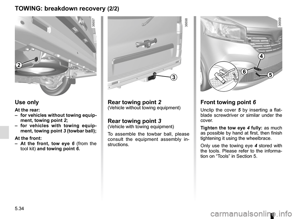
Rear towing point 2(Vehicle without towing equipment)
Rear towing point 3(Vehicle with towing equipment)
To assemble the towbar ball, please
consult the equipment assembly in-
structions.
6
Front towing point 6
Unclip the cover 5 by inserting a flat-
blade screwdriver or similar under the
cover.
Tighten the tow eye 4 fully: as much
as possible by hand at first, then finish
tightening it using the wheelbrace.
Only use the towing eye 4 stored with
the tools. Please refer to the informa-
tion on “Tools” in Section 5.
4
5
2
Use only
At the rear:
– for vehicles without towing equip- ment, towing point 2;
– for vehicles with towing equip- ment, towing point 3 (towbar ball);
At the front:
– At the front, tow eye 6 (from the
tool kit) and towing point 6.
3