2017 RENAULT TRAFIC steering
[x] Cancel search: steeringPage 139 of 294

2.13
DRIVING ADVICE, ECO-DRIVING (2/4)
An overall rating from 0 to 100 is dis-
played to let you assess your eco driv-
ing performance. The higher the rating,
the lower the fuel consumption.
Eco advice is given to help improve
your performance.
With your favourite journeys saved, you
can evaluate your performance.
For more information, please see the
multimedia system instructions.
5
ECO mode
ECO mode is a function which op-
timises fuel consumption. It acts on
certain power consuming systems in
the vehicle (heating, air conditioning,
power-assisted steering, etc.) and on
certain driving actions (acceleration,
gear changing, cruise control, deceler-
ation, etc.).
Activating the function
Press switch 4.
The 5
warning light comes on on
the instrument panel to confirm activa-
tion.
While driving, it is possible to leave the
ECO mode temporarily in order to im-
prove engine performance.
For this, depress the accelerator pedal
firmly and fully.
ECO mode is reactivated when you
take pressure off the accelerator pedal.
Disabling the function
Press switch 4.
The 5
light goes out on the instru-
ment panel to confirm deactivation.
4
3
Journey record
Once the engine is switched off, you
will see “Journey record” displayed on
the screen 3, enabling you to view in-
formation relating to your last journey.
This indicates:
– average fuel consumption;
– number of miles/kilometres travelled;
– number of miles/kilometres saved.
Page 148 of 294

2.22
Operating faults
When the system detects an operat-
ing fault the message “Check ESC” and
warning light
© and appear
on the instrument panel. In this case,
the ESC and traction control system
are deactivated.
Consult an approved dealer.
Electronic stability program
(ESC) with understeer control
and traction control
Electronic stability control ESC
This system helps you to keep control
of the vehicle in critical driving condi-
tions (avoiding an obstacle, loss of grip
on a bend, etc.).
Operating principle
A sensor in the steering wheel detects
the direction selected by the driver.
Other sensors throughout the vehicle
measure the actual direction.
The system compares driver input to
the actual trajectory of the vehicle and
corrects the trajectory if necessary by
controlling the braking of certain wheels
and/or engine power. In the event that
the system is engaged, indicator light
flashes on the instrument panel.
DRIVING CORRECTION DEVICES AND AIDS (2/5)
Understeer control
This system optimises the action of the
ESC in the case of pronounced under-
steer (loss of front axle road holding).
Traction control
This system helps to limit wheelspin of
the drive wheels and to control the ve-
hicle when pulling away accelerating or
decelerating.
Operating principle
Using the wheel sensors, the system
measures and compares the speed of
the drive wheels at all times and slows
down their over-rotation. If a wheel is
starting to slip, the system brakes au-
tomatically until the drive supplied be-
comes compatible with the level of grip
under the wheel again.
The system also adjusts the engine
speed to the grip available under the
wheels, independently of the pressure
exerted on the accelerator pedal.
These functions are an ad-
ditional aid in the event of
critical driving conditions,
enabling the vehicle behav-
iour to be adapted to suit the driving
conditions.
The functions do not take the place
of the driver. They do not increase
the vehicle’s limits and should
not encourage you to drive more
quickly. Therefore, they can under
no circumstances replace the vigi-
lance or responsibility of the driver
when manoeuvring the vehicle (the
driver must always be ready for
sudden incidents which may occur
when driving).
Page 164 of 294

2.38
REVERSING CAMERA (2/2)
The screen shows a reverse image.
The frames are a representation
projected on a flat surface. This in-
formation is to not be taken into ac-
count when superimposed on a
vertical object or an object on the
ground.
Objects which appear on the edge
of the screen may be deformed.
In very bright light (snow, vehicle in
sunshine etc.), the camera vision
may be adversely affected.
If the rear doors are open or poorly
closed, the message “BOOT OPEN”
appears and, depending on the ve-
hicle, the camera display disap-
pears.
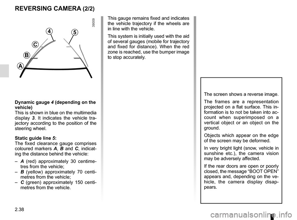
Dynamic gauge 4 (depending on the
vehicle)
This is shown in blue on the multimedia
display 3. It indicates the vehicle tra-
jectory according to the position of the
steering wheel.
Static guide line 5:
The fixed clearance gauge comprises
coloured markers A, B and C , indicat-
ing the distance behind the vehicle:
– A (red) approximately 30 centime-
tres from the vehicle;
– B (yellow) approximately 70 centi-
metres from the vehicle;
– C (green) approximately 150 centi-
metres from the vehicle. This gauge remains fixed and indicates
the vehicle trajectory if the wheels are
in line with the vehicle.
This system is initially used with the aid
of several gauges (mobile for trajectory
and fixed for distance). When the red
zone is reached, use the bumper image
to stop accurately.
4
C
B
A
5
Page 206 of 294

3.42
Using the telephone
We remind you of the need
to conform to the legislation
in force concerning the use
of such equipment.
MULTIMEDIA EQUIPMENT
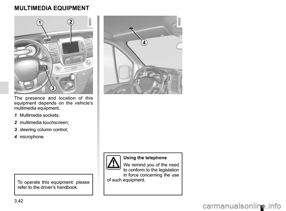
The presence and location of this
equipment depends on the vehicle’s
multimedia equipment.
1 Multimedia sockets;
2 multimedia touchscreen;
3 steering column control;
4 microphone.
To operate this equipment: please
refer to the driver’s handbook.
12
3
4
Page 233 of 294

5.11
TYRES (1/3)
For your safety, please re-
spect the speed limit.
When they need to be re-
placed, only tyres of the
same make, size, type and profile
should be used on a single axle.
They must: either have a load ca-
pacity and speed rating at least
equal to those of the original
tyres, or conform to those recom-
mended by an authorised dealer.
Failure to heed these instructions
could endanger your safety and
affect your vehicle’s roadworthi-
ness.
Risk of loss of control of the ve-
hicle.
Incidents which occur when
driving, such as striking the
kerb, may damage the tyres
and wheel rims, and could
also lead to misalignment of the
front or rear axle geometry. In this
case, have the condition of these
checked by an approved dealer.
Incorrect tyre pressures
lead to abnormal tyre wear
and unusually hot running.
These are factors which
may seriously affect safety and lead
to:
– poor road holding,
– risk of bursting or tread separa- tion.
The pressure depends on the load
and the speed of use. Adjust the
pressure according to the condi-
tions of use (refer to the label affixed
to the edge of the driver’s door).
Please be aware that a
poorly tightened or miss-
ing valve cap can make the
tyres less airtight and lead
to pressure loss.
Always use valve caps identical to
those fitted originally and tighten
them fully.
Fitting new tyres
For safety reasons, this op-
eration must be carried out
by a specialist.
Fitting different tyres may change
your vehicle as follows:
– it may mean that your vehicle no longer conforms to current regu-
lations;
– it may change the way it handles when cornering;
– it may cause the steering to be heavy;
– it may affect the use of snow chains.
Page 251 of 294

5.29
No.Allocation
1 APC load for vehicle with
RENAULT card
2 Adjustment
3 Adjustment
4 + battery for vehicles with
RENAULT card
5 Additional heating and air
conditioning
6 Supplementary passenger
compartment heating
7 Electric door mirrors,
supplementary central unit
adjustment
8 Heated door mirror
9 Radio, multimedia, rear-view
mirror, diagnostic socket
10 Pre-equipment, towbar socket
11 Timed battery, passenger
compartment unit
12 Right-hand daytime running
light, front side lights, right-hand
main beam headlight, left-hand
dipped beam headlight
13 Hazard warning lights, direction
indicator lights
FUSES (3/3)
No.
Allocation
14 Central locking of opening
elements
15 Left-hand daytime running light,
rear side light, left-hand main
beam headlight, right-hand
dipped beam headlight
16 Registration plate lighting, front
and rear fog lights
17 Alarm, horn, lighting and wiper
stalks
18 Instrument panel
19 Heater
20 Rear screen wiper, screenwash
pump, horn
21 General APC load
22 Reversing lights
23 Brake switch
24 Injection, starting
25 Airbag, steering column lock
26 Passenger side window control
27 Power-assisted steering
28 Brake lightsNo. Allocation
29 APC load for vehicle with
RENAULT card
30 General service
31 Cigarette lighter, accessories
socket
32 Heater
33 Brake light, ABS, transponder
34 Interior lighting, air-conditioning
35 Starting for vehicles with
RENAULT card
36 Rear windscreen wiper
37 Electromagnetic notification
38 Accessories socket in the
loading area
39 Driver’s side window control
motor
40 Rear accessories socket
41 BCM starting
42 Heated seats
43 Tachograph
44 Front windscreen wiper
45 Heating, air conditioning system
Page 255 of 294

5.33
TOWING: breakdown recovery (1/2)
The steering wheel must be un-
locked and the ignition key must be
in position M (ignition on) to provide
brake lights and hazard warning
lights on the towed vehicle. At night
the vehicle must have its lights on.
Unhitch the trailer, etc., if one is
being towed.
You must observe the towing regu-
lations which apply in the country in
which you are driving: do not exceed
the towing weight for your vehicle.
Contact an approved dealer.
Never use the drive shafts or axles.
These towing points may only be used
for traction: never use them for lifting
the vehicle directly or indirectly.– Use a rigid towing bar.
If a rope or cable is used
(where the law allows this),
the vehicle being towed
must be able to brake.
– A vehicle must not be towed if it is
not fit to be driven.
– Do not accelerate or brake sud- denly when towing, as this may
result in damage being caused to
the vehicle.
– When towing a vehicle, do not exceed 15 mph (25 km/h).
– Do not push the vehicle if the steering column is locked.
When the engine is
stopped, steering and brak-
ing assistance are not op-
erational.
Do not remove the key from
the ignition switch or the
card from the reader during
towing.
Page 259 of 294

5.37
OPERATING FAULTS (3/7)
The starter is activatedPOSSIBLE CAUSES WHAT TO DO
The instrument panel indicator lights are
weak or fail to light up and the starter
does not turn. Battery terminals not tight,
battery terminals discon-
nected or oxidised.Retighten or reconnect the terminals, or clean them if
they are oxidised.
Discharged battery or not
operational. Connect another battery to the faulty battery. Refer to
information on “Battery: troubleshooting” in Section 5
or replace the battery if necessary.
Do not push the vehicle if the steering column is
locked.
Faulty circuit. Consult an approved dealer.
The engine will not start. Starting conditions are not
fulfilled.Please refer to the information on “Starting, stopping
the engine” in Section 2.
The RENAULT “hands-free”
card does not work. Insert the card in the card reader in order to start the
engine.
Please refer to the information on “Starting, stopping
the engine” in Section 2.
The engine cannot be switched off. Card not detected. Insert the card in card reader.
Electronic fault. Press the starter button quickly five times.
The steering column remains locked. Steering wheel locked. Move the steering wheel while pressing the engine
start button (please refer to Section 2 “Starting, stop-
ping the engine”).
Faulty circuit. Consult an approved dealer.