2017 RENAULT TRAFIC section 4
[x] Cancel search: section 4Page 228 of 294

5.6
With the engine running and the
parking brake applied,
– unroll the hose from the container;
– connect the compressor hose 3 to
the container’s inlet 8;
– depending on the vehicle, connect the container 8 to the compressor
from the container recess 7;
– unscrew the valve cap on the rel- evant wheel and screw on the con-
tainer’s inflation adapter 1;
45
1
TYRE PRESSURE KIT (3/3)
Once the tyre is correctly inflated,
remove the kit: slowly unscrew the in-
flation adapter 1 to prevent any repair
product from escaping and store the
container in plastic packaging to pre-
vent the product from escaping.
– Affix the driving recommendation label to the dashboard where it can
easily be seen by the driver;
– Store the kit in the toolkit and re- insert it properly under the driver’s
seat.
– At the end of this initial inflation op- eration, air will still escape from the
tyre. You must drive a short distance
in order to seal the hole.
– Start immediately and drive at be- tween 12 and 40 mph (20 and
60 km/h) in order to distribute the
product evenly in the tyre and, after
driving for 2 miles (3 km), stop and
check the pressure.
– If the pressure is greater than 1.3 bar but less than the recommended
pressure (refer to the label affixed to
the edge of the driver’s door), read-
just it. Otherwise, please contact an
authorised dealer: the tyre cannot be
repaired.
8
– disconnect any accessories previ-ously connected to the vehicle’s ac-
cessories sockets;
– adapter 2 must be connected to the
vehicle accessories socket;
– press switch 4 to inflate the tyre to
the recommended pressure (please
refer to the information on “Tyre infla-
tion pressure” in Section 4);
– after a maximum of 15 minutes, stop inflating and read the pressure (on
pressure gauge 5).
Note: while the container is empty-
ing (approximately 30 seconds), the
pressure gauge 5 will briefly indicate
a pressure of up to 6 bar. The pres-
sure will then drop.
– adjust the pressure: to increase it, continue inflation with the kit; to
reduce it, press button 6.
If a minimum pressure of 1.8 bar is
not reached after 15 minutes, repair
is not possible; do not drive the ve-
hicle but contact an approved dealer.
2
3
7
6
Page 229 of 294

5.7
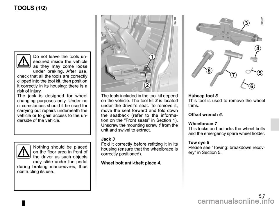
The tools included in the tool kit depend
on the vehicle. The tool kit 2 is located
under the driver’s seat. To remove it,
move the seat forward and fold down
the seatback (refer to the informa-
tion on the “Front seats” in Section 1).
Unscrew the mounting screw 1 from the
unit and swivel to extract.
Jack 3
Fold it correctly before refitting it in its
housing (ensure that the wheelbrace is
correctly positioned).
Wheel bolt anti-theft piece 4.
TOOLS (1/2)
Hubcap tool 5
This tool is used to remove the wheel
trims.
Offset wrench 6.
Wheelbrace 7
This locks and unlocks the wheel bolts
and the emergency spare wheel holder.
Tow eye 8
Please see “Towing: breakdown recov-
ery” in Section 5.
3
4
Do not leave the tools un-
secured inside the vehicle
as they may come loose
under braking. After use,
check that all the tools are correctly
clipped into the tool kit, then position
it correctly in its housing: there is a
risk of injury.
The jack is designed for wheel
changing purposes only. Under no
circumstances should it be used for
carrying out repairs underneath the
vehicle or to gain access to the un-
derside of the vehicle.
Nothing should be placed
on the floor area in front of
the driver as such objects
may slide under the pedal
during braking manoeuvres, thus
obstructing its use.
2
5
6
78
1
Page 232 of 294

5.10
CHANGING A WHEEL (2/2)
Loosen the wheel nuts and remove the
wheel.
Fit the emergency spare wheel in place
on the central hub.
Tighten the nuts and lower the jack.
With the wheels on the ground, tighten
the nuts fully and check if they are tight
as quickly as possible.
Position the trim.
Anti-theft bolt
If you use anti-theft bolts, fit these
nearest the valve (otherwise it may
not be possible to fit the wheel trim).
1
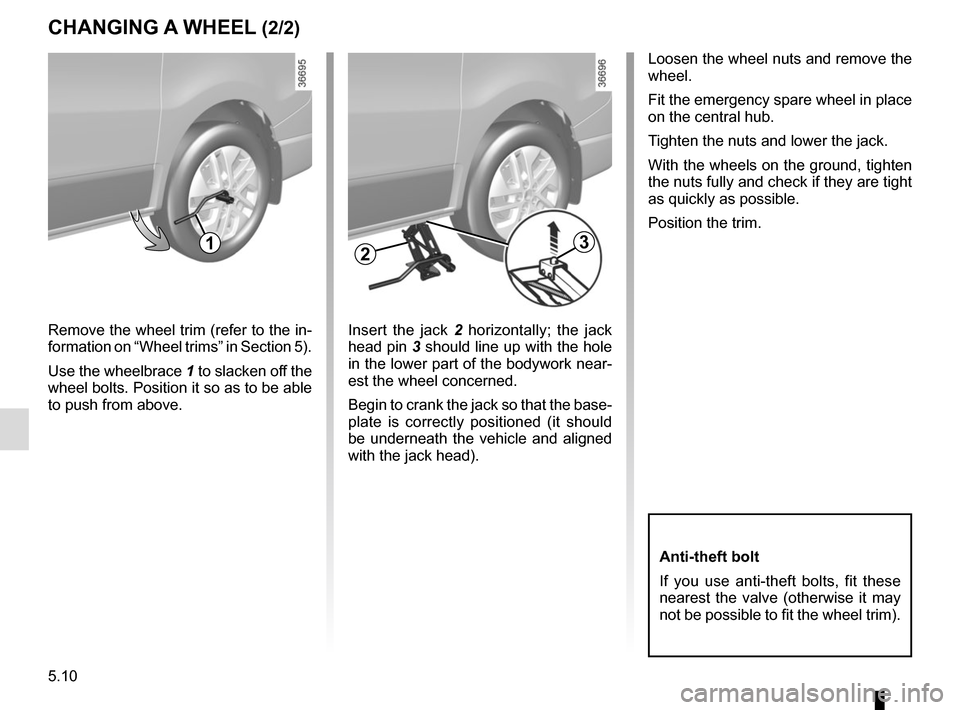
Remove the wheel trim (refer to the in-
formation on “Wheel trims” in Section 5).
Use the wheelbrace 1 to slacken off the
wheel bolts. Position it so as to be able
to push from above.
3
Insert the jack 2 horizontally; the jack
head pin 3 should line up with the hole
in the lower part of the bodywork near-
est the wheel concerned.
Begin to crank the jack so that the base-
plate is correctly positioned (it should
be underneath the vehicle and aligned
with the jack head).
2
Page 234 of 294

5.12
TYRES (2/3)
1
2
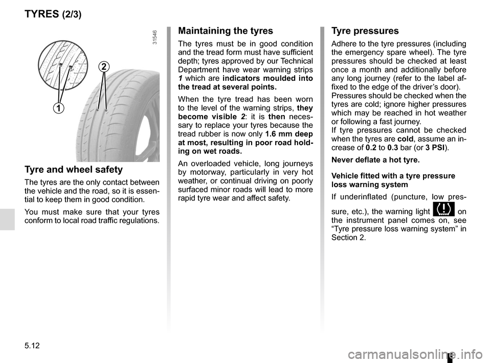
Maintaining the tyres
The tyres must be in good condition
and the tread form must have sufficient
depth; tyres approved by our Technical
Department have wear warning strips
1 which are indicators moulded into
the tread at several points.
When the tyre tread has been worn
to the level of the warning strips, they
become visible 2: it is then neces-
sary to replace your tyres because the
tread rubber is now only 1.6 mm deep
at most, resulting in poor road hold-
ing on wet roads.
An overloaded vehicle, long journeys
by motorway, particularly in very hot
weather, or continual driving on poorly
surfaced minor roads will lead to more
rapid tyre wear and affect safety.
Tyre and wheel safety
The tyres are the only contact between
the vehicle and the road, so it is essen-
tial to keep them in good condition.
You must make sure that your tyres
conform to local road traffic regulations.
Tyre pressures
Adhere to the tyre pressures (including
the emergency spare wheel). The tyre
pressures should be checked at least
once a month and additionally before
any long journey (refer to the label af-
fixed to the edge of the driver’s door).
Pressures should be checked when the
tyres are cold; ignore higher pressures
which may be reached in hot weather
or following a fast journey.
If tyre pressures cannot be checked
when the tyres are cold, assume an in-
crease of 0.2 to 0.3 bar (or 3 PSI).
Never deflate a hot tyre.
Vehicle fitted with a tyre pressure
loss warning system
If underinflated (puncture, low pres-
sure, etc.), the warning light
on
the instrument panel comes on, see
“Tyre pressure loss warning system” in
Section 2.
Page 235 of 294

5.13
Use in winter
Chains
For safety reasons, fitting snow
chains to the rear axle is strictly for-
bidden.
Chains cannot be fitted to tyres which
are larger than those originally fitted to
the vehicle.
Snow or Winter tyres
We would recommend that these be
fitted to all four wheels to ensure that
your vehicle retains maximum adhe-
sion.
Warning : These tyres sometimes have
a specific direction of rotation and a
maximum speed index which may be
lower than the maximum speed of your
vehicle.
TYRES (3/3)
Studded tyres
This type of equipment may only be
used for a limited period and as laid
down by local legislation. It is neces-
sary to observe the speed specified by
current legislation.
These tyres must, at a minimum, be
fitted to the two front wheels.
In all cases, we would recommend
that you contact an approved dealer
who will be able to advise you on
the choice of equipment which is
most suitable for your vehicle.
Emergency spare wheel
Refer to the information on the
“Emergency spare wheel” and in-
structions on “Changing a wheel” in
Section 5.
Changing wheels around
This practice is not recommended.
17” wheels cannot be
fitted with chains.
If you wish to fit snow
chains, you must use spe-
cial equipment.
Consult an approved Dealer.
Chains may only be fitted
to tyres of the same size
as those originally fitted to
your vehicle.
Page 236 of 294

5.14
FRONT HEADLIGHTS: changing bulbs (1/2)
Take care when working in
the engine compartment
as the engine cooling fan
may start to operate at any
moment without warning.
Risk of injury.
Main headlight and dipped
beam headlight
Turn the cover B a quarter turn.
Disconnect the wiring 2.
Unclip spring 1 and remove the bulb.
Bulb type: H4.
Do not touch the bulb glass. Hold it
by its base.
Replace the bulb, replace the connec-
tors and check that the cover B is re-
placed correctly.
B
A
2
1Any operation on (or modi-
fication to) the electrical
system must be performed
by an approved dealer
since an incorrect connection might
damage the electrical equipment
(harness, components and in partic-
ular the alternator). In addition, your
Dealer has all the parts required for
fitting these units.
The bulbs are under pres-
sure and can break when
replaced.
Risk of injury.
The engine must be
stopped before any action
(and not on standby): stop
the engine (please refer
to the information on “Starting and
stopping the engine” in Section 2).
Daytime running lights
Turn the bulb holder A a quarter of a
turn and remove.
Bulb type: W21W/5W.
Change the bulb and replace the bulb
holder.
Page 245 of 294

5.23
Operating faultsIf the battery is too weak to ensure cor-
rect operation, you can still start (insert
the RENAULT card in the card reader)
and lock/unlock the vehicle (refer to the
information on "Locking/unlocking the
doors" in Section 1).
RENAULT CARD: battery
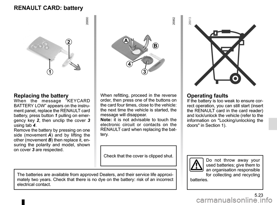
Replacing the batteryWhen the message “KEYCARD
BATTERY LOW” appears on the instru-
ment panel, replace the RENAULT card
battery, press button 1 pulling on emer-
gency key 2, then unclip the cover 3
using tab 4.
Remove the battery by pressing on one
side (movement A) and by lifting the
other (movement B) then replace it, en-
suring the polarity and model, shown
on cover 3 are respected.
Do not throw away your
used batteries; give them to
an organisation responsible
for collecting and recycling
batteries.
1
2
When refitting, proceed in the reverse
order, then press one of the buttons on
the card four times, close to the vehicle:
the next time the vehicle is started, the
message will disappear.
Note: it is not advisable to touch the
electronic circuit or contacts on the
RENAULT card when replacing the bat-
tery.
A
B
3
The batteries are available from approved Dealers, and their service lif\
e approxi-
mately two years. Check that there is no dye on the battery: risk of an \
incorrect
electrical contact.
4
Check that the cover is clipped shut.
Page 246 of 294

5.24
BATTERY: breakdown recovery (1/2)
To avoid all risk of sparks:
– Ensure that any electrical consumers (courtesy lights, etc.) are switched
off before disconnecting or recon-
necting the battery.
– When charging, stop the charger before connecting or disconnecting
the battery.
– Do not place metal objects on the battery to avoid creating a short cir-
cuit between the terminals.
– Always wait at least one minute after the engine has been switched off
before disconnecting a battery.
– Make sure that you reconnect the battery terminals after refitting.
Connecting a battery charger
The battery charger must be com-
patible with a battery with nominal
voltage of 12 volts.
Do not disconnect the battery when the
engine is running. Follow the instruc-
tions given by the manufacturer of
the battery charger you are using.
Special procedures may be
required to charge some
batteries. Contact your ap-
proved dealer.
Avoid all risk of sparks which may
cause an immediate explosion, and
charge the battery in a well-venti-
lated area. Risk of serious injury.
Handle the battery with care
as it contains sulphuric acid,
which must not come into
contact with eyes or skin. If
it does, wash the affected area with
plenty of cold water. If necessary,
consult a doctor.
Ensure that naked flames, red hot
objects and sparks do not come into
contact with the battery as there is a
risk of explosion.
The engine may be hot when car-
rying out operations in close prox-
imity. In addition, the engine cooling
fan can come on at any moment.
Risk of injury.
The engine must be
stopped before any action
(and not on standby): stop
the engine (please refer
to the information on “Starting and
stopping the engine” in Section 2).