Page 79 of 348

Activation
Remove the key or turn the ignition to the OFF/LOCK
position, and pull the multifunction lever toward the
steering wheel, within two minutes. Each time the lever is
pulled, the activation of the lights will be extended by 30
seconds. The activation of the lights can be extended to a
maximum of 210 seconds.
The warning light on the instrument panel will light up
and the corresponding message will appear in the Instru-
ment Cluster Display for as long as the function is acti-
vated. The warning light comes on when the lever is
operated and stays on until the function is automatically
deactivated. Each movement of the lever only increases the
amount of time the lights stay on.
Deactivation
Pull the multifunction lever toward the steering wheel and
hold it for more than two seconds.
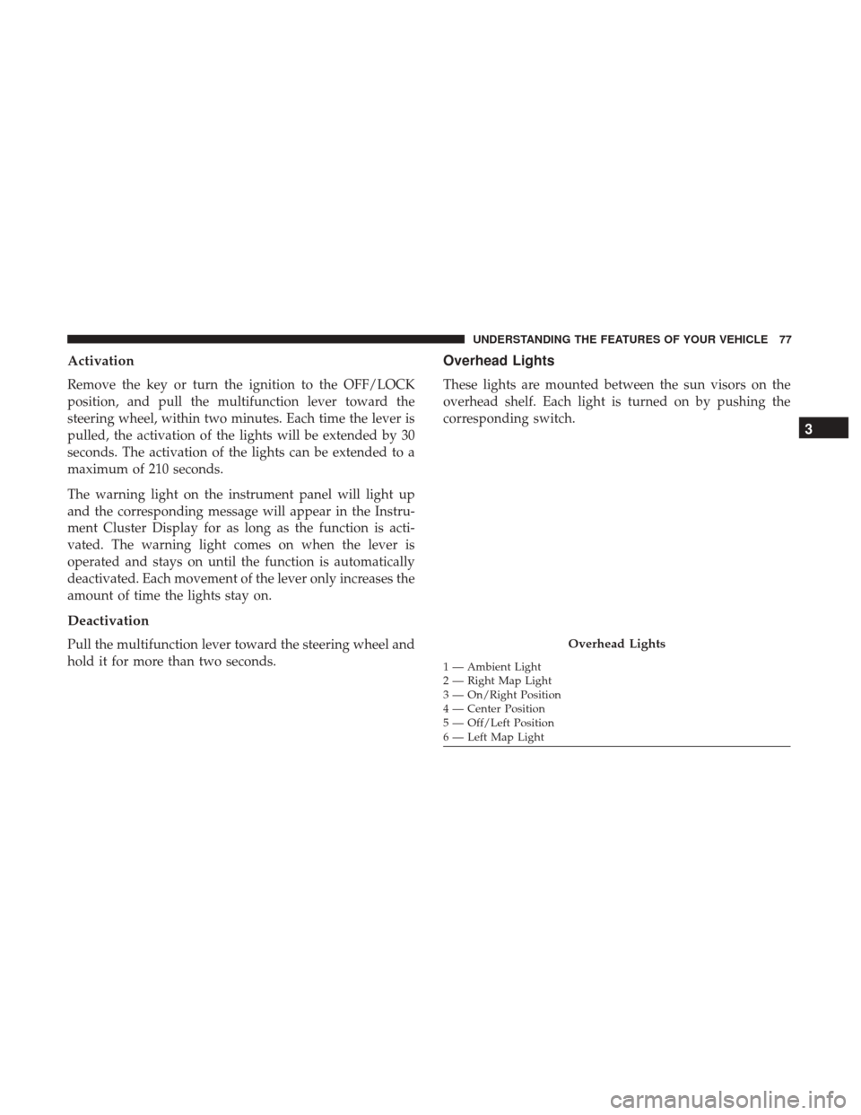
Overhead Lights
These lights are mounted between the sun visors on the
overhead shelf. Each light is turned on by pushing the
corresponding switch.
Overhead Lights
1 — Ambient Light
2 — Right Map Light
3 — On/Right Position
4 — Center Position
5 — Off/Left Position
6 — Left Map Light
3
UNDERSTANDING THE FEATURES OF YOUR VEHICLE 77
Page 83 of 348

Windshield Washer Operation
To use the washer, pull the windshield wiper/washer lever
toward the steering wheel to activate the washers. The
wipers will activate automatically for three cycles after the
lever is released. and then resume the intermittent interval
previously selected.
If the lever is pulled while in the off position, the wipers
will operate for three cycles, then turn off.
WARNING!
Sudden loss of visibility through the windshield could
lead to a collision. You might not see other vehicles or
other obstacles. To avoid sudden icing of the wind-
shield during freezing weather, warm the windshield
with the defroster before and during windshield
washer use.
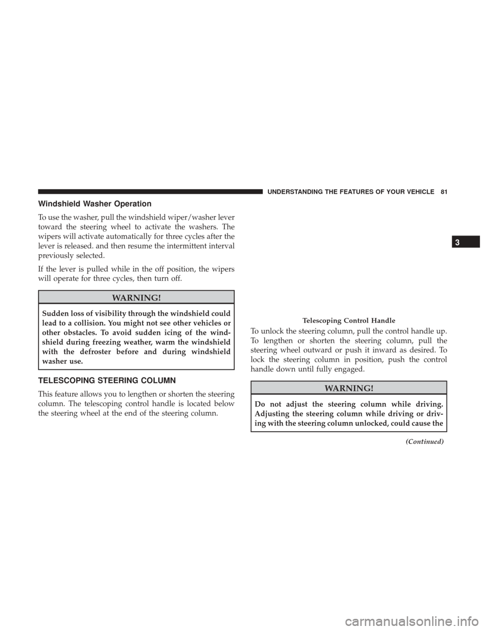
TELESCOPING STEERING COLUMN
This feature allows you to lengthen or shorten the steering
column. The telescoping control handle is located below
the steering wheel at the end of the steering column.To unlock the steering column, pull the control handle up.
To lengthen or shorten the steering column, pull the
steering wheel outward or push it inward as desired. To
lock the steering column in position, push the control
handle down until fully engaged.WARNING!
Do not adjust the steering column while driving.
Adjusting the steering column while driving or driv-
ing with the steering column unlocked, could cause the
(Continued)
Telescoping Control Handle
3
UNDERSTANDING THE FEATURES OF YOUR VEHICLE 81
Page 100 of 348

▫Clock .............................. .138
▫ USB Mode (MP3/WMA/AAC) ............138
� UCONNECT RADIOS ....................144
� UCONNECT SETTINGS ...................144
▫ Buttons On The Faceplate .................145
▫ Buttons On The Touchscreen ...............146
▫ Customer Programmable Features/Personal
Settings ............................. .146
� IPOD/USB/MP3 CONTROL — IF EQUIPPED . . . .155
▫ USB Charging Port ..................... .155
� STEERING WHEEL AUDIO CONTROLS .......156
▫ Radio Operation ....................... .156
� CD DISC MAINTENANCE .................156
� RADIO OPERATION AND MOBILE PHONES . . .157
▫ General Information ....................157 �
CLIMATE CONTROLS ....................157
▫ Manual Climate Control Overview ...........158
▫ Operating Tips ....................... .163
� UCONNECT VOICE RECOGNITION .........166
▫ Introducing Uconnect ....................166
▫ Get Started .......................... .166
▫ Basic Voice Commands ...................168
▫ Radio .............................. .169
▫ Media .............................. .169
▫ Phone .............................. .170
▫ Voice Text Reply ...................... .171
▫ General Information .................... .172
▫ Additional
Information ...................172
98 UNDERSTANDING YOUR INSTRUMENT PANEL
Page 115 of 348

Please note that the TPMS is not a substitute for proper tire
maintenance, and it is the driver ’s responsibility to main-
tain correct tire pressure, even if under-inflation has not
reached the level to trigger illumination of the TPMS low
tire pressure telltale.
Your vehicle has also been equipped with a TPMS
malfunction indicator to indicate when the system is not
operating properly. The TPMS malfunction indicator is
combined with the low tire pressure telltale. When the
system detects a malfunction, the telltale will flash for
approximately one minute and then remain continu-
ously illuminated. This sequence will continue upon
subsequent vehicle start-ups as long as the malfunction
exists. When the malfunction indicator is illuminated,
the system may not be able to detect or signal low tire
pressure as intended. TPMS malfunctions may occur for
a variety of reasons, including the installation of re-
placement or alternate tires or wheels on the vehicle that
prevent the TPMS from functioning properly. Always
check the TPMS malfunction telltale after replacing oneor more tires or wheels on your vehicle, to ensure that
the replacement or alternate tires and wheels allow the
TPMS to continue to function properly.
CAUTION!
The TPMS has been optimized for the original equip-
ment tires and wheels. TPMS pressures and warning
have been established for the tire size equipped on
your vehicle. Undesirable system operation or sensor
damage may result when using replacement equip-
ment that is not of the same size, type, and/or style.
Aftermarket wheels can cause sensor damage. Using
aftermarket tire sealants may cause the Tire Pressure
Monitoring System (TPMS) sensor to become inoper-
able. After using an aftermarket tire sealant it is
recommended that you take your vehicle to an autho-
rized dealership to have your sensor function checked.4
UNDERSTANDING YOUR INSTRUMENT PANEL 113
Page 122 of 348

Blue Telltale Indicator Lights
High Beam Indicator Light
Blue TelltaleLight What It Means
High Beam Indicator Light
This indicator shows that the high beam headlights are on. Push the multifunction control lever
away from you to switch the headlights to high beam. Pull the lever toward you to switch the
headlights back to low beam. Pull the lever toward you for a temporary high beam on,
�flash to
pass� scenario.
INSTRUMENT CLUSTER DISPLAY
Your vehicle may be equipped with an Instrument Cluster
Display, which offers useful information to the driver. With
the ignition in the STOP/OFF position (and the key
removed, for vehicles with mechanical key), opening/
closing of a door will activate the display for viewing, and
display the total miles or kilometers in the odometer. Your
Instrument Cluster Display is designed to display impor-
tant information about your vehicle’s systems and features. Using a driver interactive display located on the instru-
ment panel, your Instrument Cluster Display can show you
how systems are working and give you warnings when
they aren’t. The steering wheel mounted controls allow
you to scroll through and enter the main menus and
submenus. You can access the specific information you
want and make selections and adjustments.
120 UNDERSTANDING YOUR INSTRUMENT PANEL
Page 141 of 348

Due to the extensive range of brands and models of storage
devices available on the market, not all devices are com-
patible with proper functioning of the car radio.
NOTE:The car radio is only compatible with USB mass
storage devices that are fully compatible with the USB 2.0
standard. Use quality USB devices only.
In USB mode, the radio plays MP3, WMA and AAC files
stored on the device connected to the USB port that is
located on the lower right side of the steering wheel on the
instrument panel. To enter USB mode, you must push the SRC button. When
you enter USB mode, the display shows
�LOADING�while
the radio checks whether the connected device is valid.
If there is no USB device, an invalid USB device, or a valid
device that is defective, the display will show �ERR USB�
for two seconds and the radio remains in TUNER mode. If
a valid device does not contain any playable files (i.e. MP3,
WMA or AAC), the display will show �NO MUSIC�for two
seconds and the radio remains in TUNER mode.
4
UNDERSTANDING YOUR INSTRUMENT PANEL 139
Page 151 of 348

Safety/Assistance
After pressing the “Safety/Assistance” button on the
touchscreen, the following settings will be available:
Setting NameSelectable Options
ParkView Rear Backup Camera Ac- tive Guide Lines — If Equipped
NOTE: The “ParkView Backup Camera Active Guide Lines” setting overlays the Rear Backup Camera image with
active, or dynamic, grid lines to help illustrate the width of the vehicle and its project back up path, based on the
steering wheel position when the option is checked. A dashed center line overlay indicates the center of the vehicle to
assist with parking or aligning to a hitch/receiver.
ParkView Backup Camera Delay — If Equipped On
Off
NOTE:
The “ParkView Backup Camera Delay” setting determines whether or not the screen will display the rear view image
with dynamic grid lines for up to 10 seconds after the vehicle is shifted out of REVERSE. This delay will be canceled
if the vehicle’s speed exceeds 8 mph (13 km/h), the transmission is shifted into PARK, or the ignition is switched to
the OFF position.
4
UNDERSTANDING YOUR INSTRUMENT PANEL 149
Page 158 of 348

WARNING!
Do not plug in or remove the iPod or external device
while driving. Failure to follow this warning could
result in a collision.
STEERING WHEEL AUDIO CONTROLS
The remote sound system controls are located on the
surface of the steering wheel.
The right-hand control is a rocker-type switch and controls
the SCAN functions of the sound system.The left-hand control is a rocker-type switch and controls
the volume of the sound system plus a button to mute the
Sound System.
The following describes the right-hand control operation in
each mode.
Radio Operation
Pushing the top of the switch will “Scan” up for the next
listenable station and pushing the bottom of the switch will
“Scan” down for the next listenable station.
CD DISC MAINTENANCE
To keep a CD in good condition, take the following
precautions:
1. Handle the disc by its edge; avoid touching the surface.
2. If the disc is stained, clean the surface with a soft cloth,
wiping from center to edge.
3. Do not apply paper or tape to the disc; avoid scratching the disc.
4. Do not use solvents such as benzene, thinner, cleaners, or anti-static sprays.
5. Store the disc in its case after playing.
Remote Sound System Controls
156 UNDERSTANDING YOUR INSTRUMENT PANEL