Page 171 of 534

NOTE:•It may take up to 30 seconds or longer in some cases
for the channel to train.
• If the Instrument Cluster Display shows “DID NOT
TRAIN”, repeat from Step 2.
5. Push and hold the programmed HomeLink button. The Instrument Cluster Display will display “CHANNEL #
TRANSMIT.” If the garage door opener/device acti-
vates, programming is complete.
To program the remaining two HomeLink buttons, repeat
each step for each remaining button. DO NOT erase the
channels.
Reprogramming A Single HomeLink Button
(Non-Rolling Code)
To reprogram a channel that has been previously trained,
follow these steps:
1. Cycle the ignition to the ON/RUN position.
2. Push and hold the desired HomeLink button until the indicator light begins to flash after 20 seconds. Do not
release the button. 3.
Without releasing the button proceed with “Program-
ming A Non-Rolling Code” step 2 and follow all remain-
ing steps.
Canadian/Gate Operator Programming
For programming transmitters in Canada/United States
that require the transmitter signals to “time-out” after
several seconds of transmission.
Canadian radio frequency laws require transmitter signals
to time-out (or quit) after several seconds of transmission –
which may not be long enough for HomeLink to pick up
the signal during programming. Similar to this Canadian
law, some U.S. gate operators are designed to time-out in
the same manner.
It may be helpful to unplug the device during the cycling
process to prevent possible overheating of the garage door
or gate motor.
1. Turn the ignition switch to the ON/RUN position.
For vehicle’s equipped with Keyless Enter-N-Go, place the
ignition in the RUN position with the Engine ON.
2. Place the hand - held transmitter 1 to 3 inches (3 to 8 cm) away from the HomeLink button you wish to program.3
UNDERSTANDING THE FEATURES OF YOUR VEHICLE 169
Page 179 of 534

operation to latching or momentary, power source of either
battery or ignition, and ability to hold last state across key
cycles.
NOTE:Holding last state conditions are met when switch
type is set to latching and power source is set to ignition.
For further information on using the auxiliary switches,
please refer to the Ram Body Builders Guide by accessing
www.rambodybuilder.com and choosing the appropriate
links.
CIGAR LIGHTER AND ASH RECEIVER — IF
EQUIPPED
A removable ash receiver and cigar lighter are available.
For vehicles with a bench seat, the cupholder tray can be
used to hold the ash receiver.
For vehicles equipped with a floor console, the cupholders
may be used.
POWER INVERTER — IF EQUIPPED
A 115 Volt (150 Watts Maximum) outlet is located on the
center stack of the instrument panel, to the right of the
radio. This outlet can power cellular phones, electronics and other low power devices requiring power up to 150
Watts. Certain high-end video game consoles will exceed
this power limit, as will most power tools.
The power inverter is designed with built-in overload
protection. If the power rating of 150 Watts is exceeded, the
power inverter will automatically shut down. Once the
electrical device has been removed from the outlet the
inverter should automatically reset.
To turn on the power outlet, simply plug in the device. The
outlet automatically turns off when the device is un-
plugged.Power Inverter Outlet
3
UNDERSTANDING THE FEATURES OF YOUR VEHICLE 177
Page 195 of 534

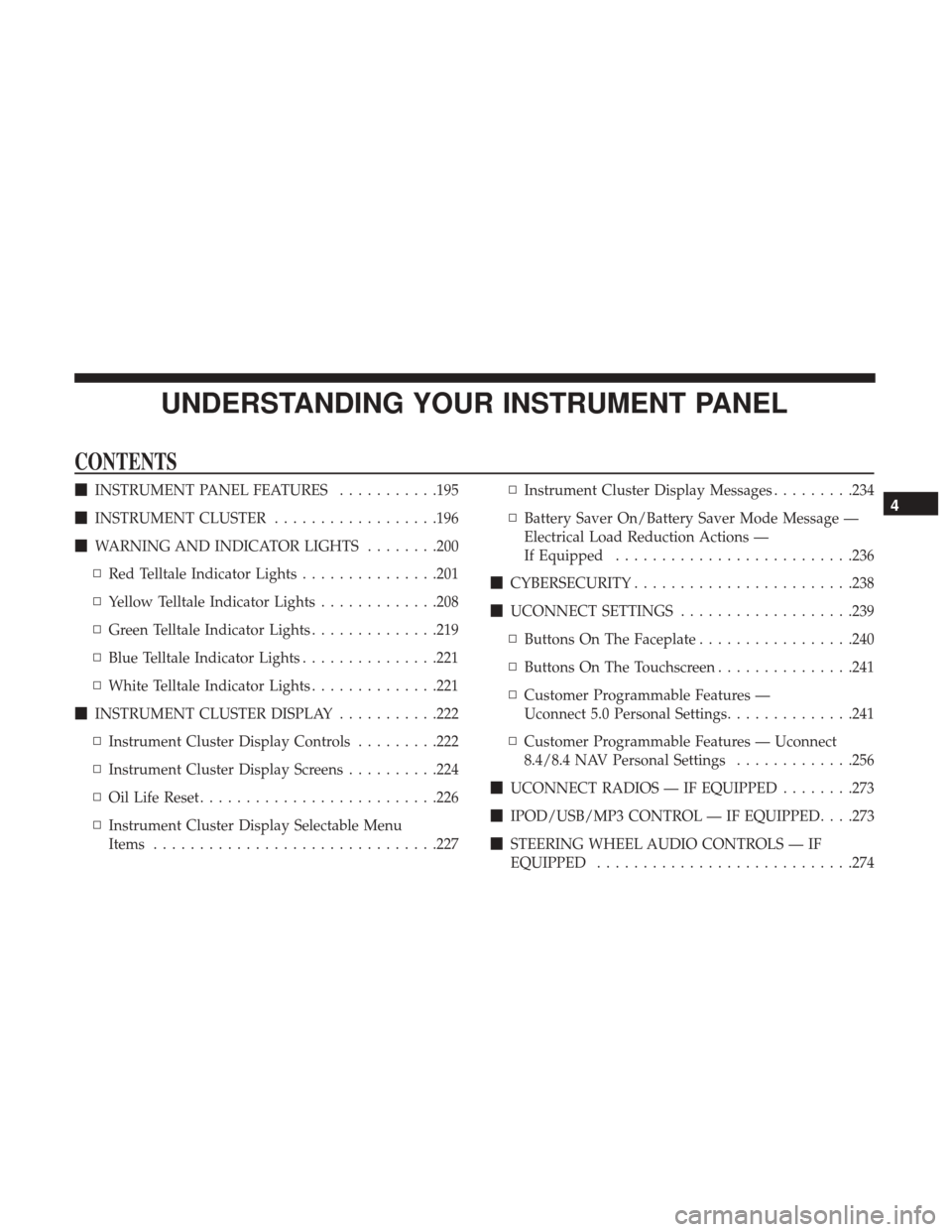
UNDERSTANDING YOUR INSTRUMENT PANEL
CONTENTS
�INSTRUMENT PANEL FEATURES ...........195
� INSTRUMENT CLUSTER ..................196
� WARNING AND INDICATOR LIGHTS ........200
▫ Red Telltale Indicator Lights ...............201
▫ Yellow Telltale Indicator Lights .............208
▫ Green Telltale Indicator Lights ..............219
▫ Blue Telltale Indicator Lights ...............221
▫ White Telltale Indicator Lights ..............221
� INSTRUMENT CLUSTER DISPLAY ...........222
▫ Instrument Cluster Display Controls .........222
▫ Instrument Cluster Display Screens ..........224
▫ Oil Life Reset ......................... .226
▫ Instrument Cluster Display Selectable Menu
Items .............................. .227▫
Instrument Cluster Display Messages .........234
▫ Battery Saver On/Battery Saver Mode Message —
Electrical Load Reduction Actions —
If Equipped ......................... .236
� CYBERSECURITY ....................... .238
� UCONNECT SETTINGS ...................239
▫ Buttons On The Faceplate .................240
▫ Buttons On The Touchscreen ...............241
▫ Customer Programmable Features —
Uconnect 5.0 Personal Settings ..............241
▫ Customer Programmable Features — Uconnect
8.4/8.4 NAV Personal Settings .............256
� UCONNECT RADIOS — IF EQUIPPED ........273
� IPOD/USB/MP3 CONTROL — IF EQUIPPED . . . .273
� STEERING WHEEL AUDIO CONTROLS — IF
EQUIPPED ........................... .2744
Page 196 of 534

▫Radio Operation ....................... .274
▫ CD Player — If Equipped .................274
� CD/DVD DISC MAINTENANCE ............275
� RADIO OPERATION AND MOBILE DEVICES . . .275
▫ Regulatory And Safety Information ..........275
� CLIMATE CONTROLS ....................277
▫ Manual Climate Controls Without A Touchscreen —
If Equipped ......................... .277
▫ Climate Controls With a Touchscreen .........282
▫ Automatic Temperature Control (ATC) — If
Equipped ........................... .291
▫ Operating Tips ....................... .291
� PERSONALIZED MENU BAR ...............294
� UCONNECT VOICE RECOGNITION .........294
▫ Introducing Uconnect ....................294
▫ Get Started .......................... .295
▫ Basic Voice Commands ...................297
▫ Radio .............................. .298▫
Media .............................. .300
▫ Phone .............................. .302
▫ Voice Text Reply ...................... .303
▫ Climate (8.4/8.4 NAV) ...................305
▫ Navigation (8.4 /8.4 NAV) ................306
▫ Uconnect Access (8.4/8.4 NAV) .............306
▫ Vehicle Health Alert ....................307
▫ Register (8.4/8.4 NAV) ...................308
▫ Mobile App (8.4/8.4 NAV) ................308
▫ Voice Texting (8.4/8.4 NAV) ...............309
▫ Y
elp (8.4/8.4 NAV) ..................... .310
▫ SiriusXM Travel Link (8.4/8.4 NAV) ..........311
▫ Siri Eyes Free — If Equipped ..............312
▫ Do Not Disturb ....................... .314
▫ General Information .....................315
▫ Additional Information ...................316
194 UNDERSTANDING YOUR INSTRUMENT PANEL
Page 197 of 534
INSTRUMENT PANEL FEATURES
1 — Headlight Switch7 — 115v Power Inverter Outlet13 — Gear Selector/Transfer Case Position
Switch — If Equipped
2 — Instrument Cluster 8 — Power Outlet — If Equipped14 — Ignition Switch
3 — Radio 9 — Lower Switch Bank15 — Hood Release
4 — Hazard Switch 10 — Instrument Panel Drawer16 — Parking Brake Release
5 — Upper Glove Compartment 11 — Climate Controls
6 — Lower Glove Compartment 12 — Power Outlet/Cigar Lighter — If
Equipped
4
UNDERSTANDING YOUR INSTRUMENT PANEL 195
Page 225 of 534
The Instrument Cluster Display Menu items may consist of
the following:
•Speedometer
• Vehicle Info
• Fuel Economy Info
• Trip A
• Trip B
• Stop/Start Info (If Equipped)
• Audio •
Trailer Tow
• Stored Messages
• Screen Setup
• Vehicle Settings (Not Equipped with a Uconnect 5.0 &
8.4 radio)
The system allows the driver to select information by
pushing the following Instrument Cluster Display Control
buttons located on the left side of the steering wheel:
Premium Instrument Cluster Display
Instrument Cluster Display Control Buttons
4
UNDERSTANDING YOUR INSTRUMENT PANEL 223
Page 232 of 534

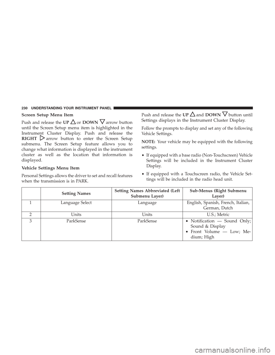
Screen Setup Menu Item
Push and release theUPorDOWNarrow button
until the Screen Setup menu item is highlighted in the
Instrument Cluster Display. Push and release the
RIGHT
arrow button to enter the Screen Setup
submenu. The Screen Setup feature allows you to
change what information is displayed in the instrument
cluster as well as the location that information is
displayed.
Vehicle Settings Menu Item
Personal Settings allows the driver to set and recall features
when the transmission is in PARK. Push and release the
UP
andDOWNbutton until
Settings displays in the Instrument Cluster Display.
Follow the prompts to display and set any of the following
Vehicle Settings.
NOTE: Your vehicle may be equipped with the following
settings.
• If equipped with a base radio (Non-Touchscreen) Vehicle
Settings will be included in the Instrument Cluster
Display.
• If equipped with a Touchscreen radio, the Vehicle Set-
tings will be included in the radio head unit.
Setting Names Setting Names Abbreviated (Left
Submenu Layer) Sub-Menus (Right Submenu
Layer)
1 Language Select LanguageEnglish, Spanish, French, Italian,
German, Dutch
2 Units UnitsU.S.; Metric
3 ParkSense ParkSense
•Notification — Sound Only;
Sound & Display
• Front Volume — Low; Me-
dium; High
230 UNDERSTANDING YOUR INSTRUMENT PANEL
Page 239 of 534

Loss of the battery charge may indicate one or more of the
following conditions:
•The charging system cannot deliver enough electrical
power to the vehicle system because the electrical loads
are larger than the capability of charging system. The
charging system is still functioning properly.
• Turning on all possible vehicle electrical loads (e.g.
HVAC to max settings, exterior and interior lights,
overloaded power outlets +12V, 115V AC, USB ports)
during certain driving conditions (city driving, towing,
frequent stopping).
• Installing options like additional lights, upfitter electri-
cal accessories, audio systems, alarms and similar de-
vices.
• Unusual driving cycles (short trips separated by long
parking periods).
• The vehicle was parked for an extended period of time
(weeks, months).
• The battery was recently replaced and was not charged
completely.
• The battery was discharged by an electrical load left on
when the vehicle was parked. •
The battery was used for an extended period with the
engine not running to supply radio, lights, chargers,
+12V portable appliances like vacuum cleaners, game
consoles and similar devices.
What to do when an electrical load reduction action
message is present (“Battery Saver On” or “Battery Saver
Mode”)
During a trip:
• Reduce power to unnecessary loads if possible:
– Turn off redundant lights (interior or exterior)
– Check what may be plugged in to power outlets +12V, 115V AC, USB ports
– Check HVAC settings (blower, temperature)
– Check the audio settings (volume)
After a trip:
• Check if any aftermarket equipment was installed (ad-
ditional lights, upfitter electrical accessories, audio sys-
tems, alarms) and review specifications if any (load and
Ignition Off Draw currents).
• Evaluate the latest driving cycles (distance, driving time
and parking time).
4
UNDERSTANDING YOUR INSTRUMENT PANEL 237