Page 257 of 534
Restore Settings
After pressing the “Restore Settings” button on the touch-
screen the following settings will be available:
Setting NameSelectable Options
Restore Settings YesCancel
NOTE: When the “Restore Settings” feature is selected it will reset the Display, Clock, Audio, and Radio Settings to
their default settings. If “Yes” is selected a pop-up will appear asking �Are you sure you want to reset your settings
to default?” select “Yes” to restore, or “Cancel” to exit.
Clear Personal Data
After pressing the “Clear Personal Data Settings” button on
the touchscreen, the following settings will be available:
Setting Name Selectable Options
Clear Personal Data YesCancel
NOTE: When this feature is selected it will remove all personal data including Bluetooth devices and presets. If “Yes”
is selected a pop-up will appear asking �Are you sure you want to clear all personal data?” select “Yes” to Clear, or
“Cancel” to exit.
4
UNDERSTANDING YOUR INSTRUMENT PANEL 255
Page 281 of 534

IconDescription
Front Defrost Setting
Turn the Mode Control knob to the Defrost mode. Air comes from the windshield and side win-
dow demist outlets. When the defrost button is selected, the blower level will increase. Use De-
frost mode with maximum temperature settings for best windshield and side window defrosting
and defogging. Performing this function will cause the ATC to switch into manual mode. If the
front defrost mode is turned off the climate system will return the previous setting.
Rear Defrost Button
Push and release the Rear Defrost Control button to turn ON the rear window defroster and the
heated outside mirrors (if equipped). An indicator will illuminate when the rear window de-
froster is ON. The rear window defroster automatically turns OFF after 10 minutes.
Temperature Control
Use this control knob to regulate the temperature of the air inside the passenger compartment.
Rotating the knob counterclockwise, from top center into the blue area of the scale, indicates
cooler temperatures. Rotating the knob clockwise, into the red area, indicates warmer tempera-
tures.
Blower Control
There are seven blower speeds. Use this control knob to regulate the amount of air forced
through the system in any mode you select. The blower speed increases as you move the con-
trol clockwise from the OFF position.
NOTE:Depending on the configuration, your vehicle may be equipped with four blower
speeds.
4
UNDERSTANDING YOUR INSTRUMENT PANEL 279
Page 306 of 534

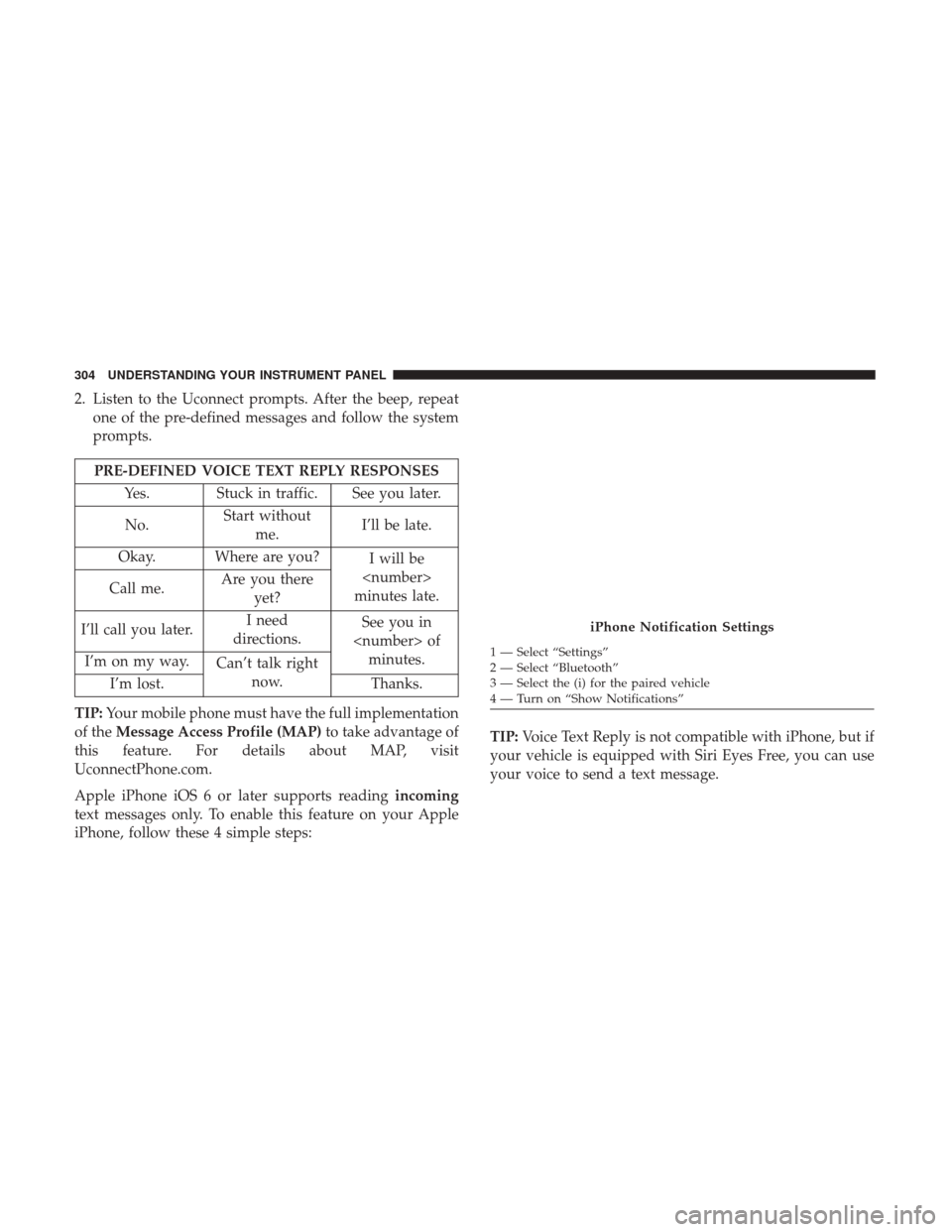
2. Listen to the Uconnect prompts. After the beep, repeatone of the pre-defined messages and follow the system
prompts.
PRE-DEFINED VOICE TEXT REPLY RESPONSES
Yes. Stuck in traffic. See you later.
No. Start without
me. I’ll be late.
Okay. Where are you? I will be
minutes late.
Call me. Are you there
yet?
I’ll call you later. I need
directions. See you in
of minutes.
I’m on my way. Can’t talk right
now.
I’m lost. Thanks.
TIP: Your mobile phone must have the full implementation
of the Message Access Profile (MAP) to take advantage of
this feature. For details about MAP, visit
UconnectPhone.com.
Apple iPhone iOS 6 or later supports reading incoming
text messages only. To enable this feature on your Apple
iPhone, follow these 4 simple steps: TIP:
Voice Text Reply is not compatible with iPhone, but if
your vehicle is equipped with Siri Eyes Free, you can use
your voice to send a text message.
iPhone Notification Settings
1 — Select “Settings”
2 — Select “Bluetooth”
3 — Select the (i) for the paired vehicle
4 — Turn on “Show Notifications”
304 UNDERSTANDING YOUR INSTRUMENT PANEL
Page 491 of 534
CavityCartridge Fuse Micro Fuse Description
F33 20 Amp Blue –Special Services Vehicle Only
F34 30 Amp Pink –Vehicle System Interface Module #2 – If
Equipped
F35 30 Amp Pink –Sunroof – If Equipped
F36 30 Amp Pink –Rear Defroster – If Equipped
F37 30 Amp Pink –Cummins Diesel Fuel Heater #2 – If
Equipped
F38 30 Amp Pink –Power Inverter 115V AC – If Equipped
F39 20 Amp Blue –Power Outlet – Special Services Only
F41 –10 Amp Red Active Grill Shutter – If Equipped
F42 –20 Amp Yellow Horn
F44 –10 Amp Red Diagnostic Port
F46 –10 Amp Red Upfitter – If Equipped
F49 –10 Amp Red Instrument Panel Cluster (Except Fleet Ve-
hicles)
F50 –20 Amp Yellow Air Suspension Control Module – If
Equipped
F51 –10 Amp Red Ignition Node Module / Keyless Ignition
(Instrument Panel Cluster – Fleet VehiclesOnly)
F52 –5 Amp Tan Battery Sensor
7
MAINTAINING YOUR VEHICLE 489