2017 Ram 2500 brake light
[x] Cancel search: brake lightPage 507 of 734

attempt to stop the sway. TSC will become active automati-
cally once an excessively swaying trailer is recognized.
NOTE:TSC cannot stop all trailers from swaying. Always
use caution when towing a trailer and follow the trailer
tongue weight recommendations. Refer to “Trailer Tow-
ing” in this section for further information.
When TSC is functioning, the “ESC Activation/
Malfunction Indicator Light” will flash, the engine power
may be reduced and you may feel the brakes being applied
to individual wheels to attempt to stop the trailer from
swaying. TSC is disabled when the ESC system is in the
“Partial Off” or “Full Off” modes.
WARNING!
If TSC activates while driving, slow the vehicle down,
stop at the nearest safe location, and adjust the trailer
load to eliminate trailer sway.
Hill Descent Control (HDC) — If Equipped
HDC is intended for low speed off road driving while in
4WD Low Range. HDC maintains vehicle speed while
descending hills during various driving situations. HDC
controls vehicle speed by actively controlling the brakes.
HDC has three states:
1. Off (feature is not enabled and will not activate).
2. Enabled (feature is enabled and ready but activation conditions are not met, or driver is actively overriding
with brake or throttle application).
3. Active (feature is enabled and actively controlling ve- hicle speed).
Enabling HDC
HDC is enabled by pushing the HDC switch, but the
following conditions must also be met to enable HDC:
• Driveline is in 4WD Low Range
• Vehicle speed is below 5 mph (8 km/h).
• Parking brake is released.
• Driver door is closed.
5
STARTING AND OPERATING 505
Page 565 of 734

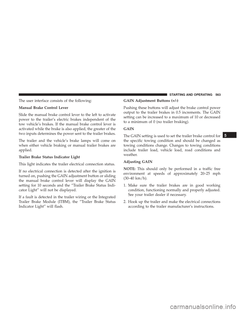
The user interface consists of the following:
Manual Brake Control Lever
Slide the manual brake control lever to the left to activate
power to the trailer’s electric brakes independent of the
tow vehicle’s brakes. If the manual brake control lever is
activated while the brake is also applied, the greater of the
two inputs determines the power sent to the trailer brakes.
The trailer and the vehicle’s brake lamps will come on
when either vehicle braking or manual trailer brakes are
applied.
Trailer Brake Status Indicator Light
This light indicates the trailer electrical connection status.
If no electrical connection is detected after the ignition is
turned on, pushing the GAIN adjustment button or sliding
the manual brake control lever will display the GAIN
setting for 10 seconds and the “Trailer Brake Status Indi-
cator Light” will not be displayed.
If a fault is detected in the trailer wiring or the Integrated
Trailer Brake Module (ITBM), the “Trailer Brake Status
Indicator Light” will flash.GAIN Adjustment Buttons (+/-)
Pushing these buttons will adjust the brake control power
output to the trailer brakes in 0.5 increments. The GAIN
setting can be increased to a maximum of 10 or decreased
to a minimum of 0 (no trailer braking).
GAIN
The GAIN setting is used to set the trailer brake control for
the specific towing condition and should be changed as
towing conditions change. Changes to towing conditions
include trailer load, vehicle load, road conditions and
weather.
Adjusting GAIN
NOTE:
This should only be performed in a traffic free
environment at speeds of approximately 20–25 mph
(30–40 km/h).
1. Make sure the trailer brakes are in good working condition, functioning normally and properly adjusted.
See your trailer dealer if necessary.
2. Hook up the trailer and make the electrical connections according to the trailer manufacturer’s instructions.
5
STARTING AND OPERATING 563
Page 566 of 734

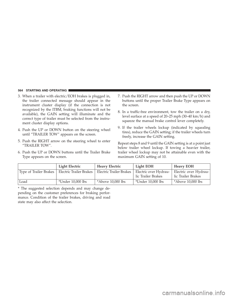
3. When a trailer with electric/EOH brakes is plugged in,the trailer connected message should appear in the
instrument cluster display (if the connection is not
recognized by the ITBM, braking functions will not be
available), the GAIN setting will illuminate and the
correct type of trailer must be selected from the instru-
ment cluster display options.
4. Push the UP or DOWN button on the steering wheel until “TRAILER TOW” appears on the screen.
5. Push the RIGHT arrow on the steering wheel to enter “TRAILER TOW”.
6. Push the UP or DOWN buttons until the Trailer Brake Type appears on the screen. 7. Push the RIGHT arrow and then push the UP or DOWN
buttons until the proper Trailer Brake Type appears on
the screen.
8. In a traffic-free environment, tow the trailer on a dry, level surface at a speed of 20–25 mph (30–40 km/h) and
squeeze the manual brake control lever completely.
9. If the trailer wheels lockup (indicated by squealing tires), reduce the GAIN setting; if the trailer wheels turn
freely, increase the GAIN setting.
Repeat steps 8 and 9 until the GAIN setting is at a point just
below trailer wheel lockup. If towing a heavier trailer,
trailer wheel lockup may not be attainable even with the
maximum GAIN setting of 10.
Light Electric Heavy Electric Light EOH Heavy EOH
Type of Trailer Brakes Electric Trailer Brakes Electric Trailer Brakes Electric over Hydrau- lic Trailer BrakesElectric over Hydrau-
lic Trailer Brakes
Load *Under 10,000 lbs *Above 10,000 lbs *Under 10,000 lbs *Above 10,000 lbs
* The suggested selection depends and may change de-
pending on the customer preferences for braking perfor-
mance. Condition of the trailer brakes, driving and road
state may also affect the selection.
564 STARTING AND OPERATING
Page 567 of 734

Display Messages
The trailer brake control interacts with the instrument
cluster display. Display messages, along with a single
chime, will be displayed when a malfunction is determined
in the trailer connection, trailer brake control, or on the
trailer. Refer to “Instrument Cluster Display” in “Under-
standing Your Instrument Panel” for further information.
CAUTION!
Connecting a trailer that is not compatible with the
ITBM system may result in reduced or complete loss of
trailer braking. There may be a increase in stopping
distance or trailer instability which could result in
damage to your vehicle, trailer, or other property.
WARNING!
Connecting a trailer that is not compatible with the
ITBM system may result in reduced or complete loss of
trailer braking. There may be a increase in stopping
distance or trailer instability which could result in
personal injury.NOTE:
•
An aftermarket controller may be available for use with
trailers with air or electric-over-hydraulic trailer brake
systems. To determine the type of brakes on your trailer
and the availability of controllers, check with your
trailer manufacturer or dealer.
• Removal of the ITBM will cause errors and it may cause
damage to the electrical system and electronic modules
of the vehicle. See your authorized dealer if an aftermar-
ket module is to be installed.
Towing Requirements — Trailer Lights And Wiring
(If Equipped)
Whenever you pull a trailer, regardless of the trailer size,
stoplights and turn signals on the trailer are required for
motoring safety.
The Trailer Tow Package may include a four- and seven-pin
wiring harness. Use a factory approved trailer harness and
connector.
NOTE: Do not cut or splice wiring into the vehicles wiring
harness.
The electrical connections are all complete to the vehicle
but you must mate the harness to a trailer connector. Refer
5
STARTING AND OPERATING 565
Page 577 of 734

CAUTION!
It is necessary to follow these steps to be certain that
the transfer case is fully in NEUTRAL (N) before
recreational towing to prevent damage to internal
parts.
1. Bring the vehicle to a complete stop, with the engine running. Firmly apply the parking brake.
2. Shift the transmission to NEUTRAL.
NOTE: If vehicle is equipped with air suspension, ensure
the vehicle is set to Normal Ride Height.
3. Press and hold the brake pedal.
4. Depress the clutch pedal on a manual transmission.
5. With manual shift transfer case, shift the transfer case lever into NEUTRAL (N).
• With electronic shift transfer case, push and hold the
transfer case NEUTRAL (N) button. Some models
have a small, recessed “N” button (at the center of the
transfer case switches) that must be pushed using a
ballpoint pen or similar object. Other models have a
rectangular NEUTRAL switch, below the rotary trans-
fer case control knob. The NEUTRAL (N) indicator light will blink while the shift is in progress. The light
will stop blinking (stay on solid) when the shift to
NEUTRAL (N) is complete. After the shift is completed
and the NEUTRAL (N) light stays on, release the
NEUTRAL (N) button.
6. Release the parking brake.
7. Shift the transmission into REVERSE.
8. Release the brake pedal (and clutch pedal on manual transmissions) for five seconds and ensure that there is
no vehicle movement.
9. Repeat steps 7 and 8 with automatic transmission in DRIVE or manual transmission in first gear.
10. Shift the transmission to NEUTRAL. Firmly apply the parking brake. Turn OFF the engine. For vehicles with
Keyless Enter-N-Go, push and hold the ENGINE
START/STOP button until the engine shuts off.
11. Shift the transmission into PARK or place manual transmission in gear (NOT in Neutral). On 8-speed
transmissions the shifter will automatically select
PARK when the engine is turned off.
5
STARTING AND OPERATING 575
Page 578 of 734

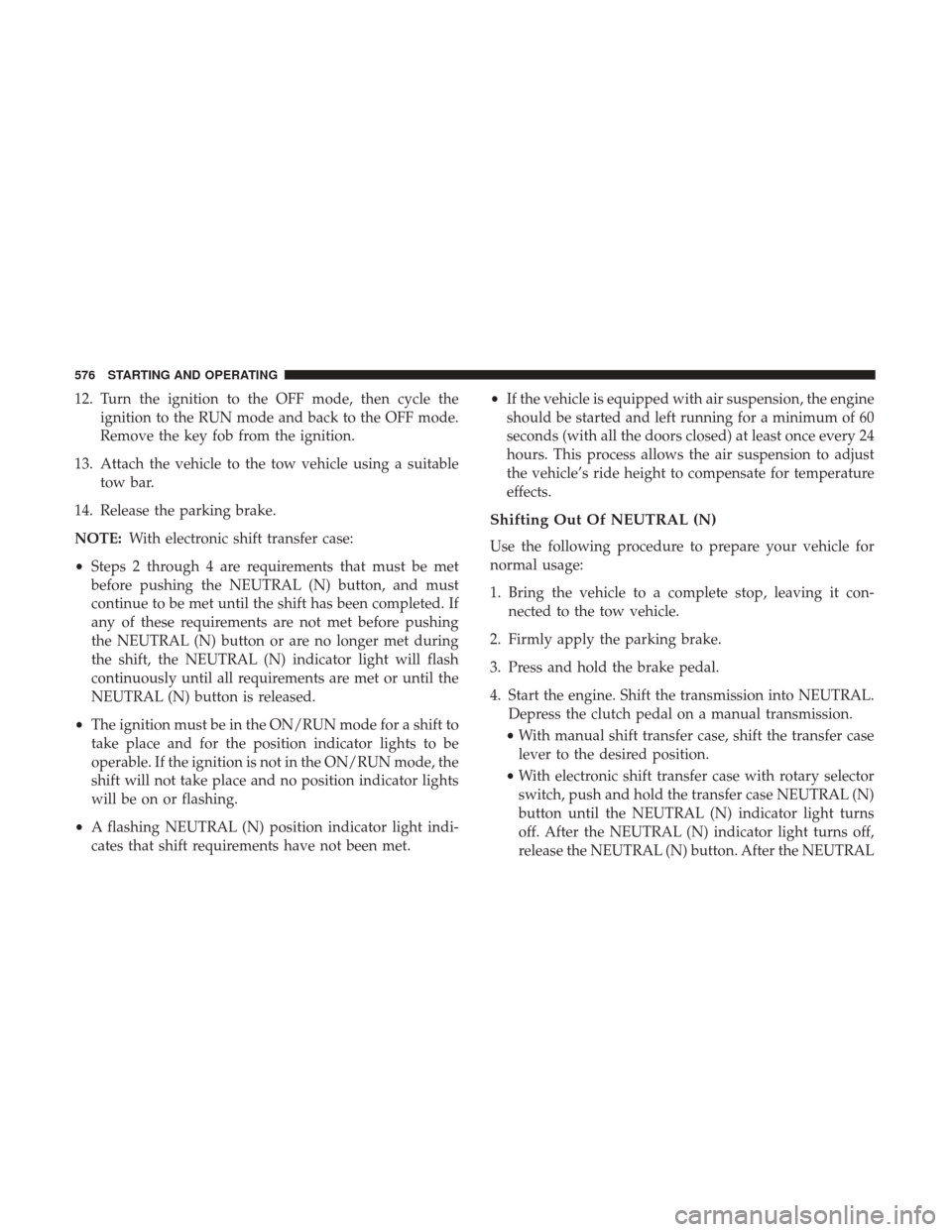
12. Turn the ignition to the OFF mode, then cycle theignition to the RUN mode and back to the OFF mode.
Remove the key fob from the ignition.
13. Attach the vehicle to the tow vehicle using a suitable tow bar.
14. Release the parking brake.
NOTE: With electronic shift transfer case:
• Steps 2 through 4 are requirements that must be met
before pushing the NEUTRAL (N) button, and must
continue to be met until the shift has been completed. If
any of these requirements are not met before pushing
the NEUTRAL (N) button or are no longer met during
the shift, the NEUTRAL (N) indicator light will flash
continuously until all requirements are met or until the
NEUTRAL (N) button is released.
• The ignition must be in the ON/RUN mode for a shift to
take place and for the position indicator lights to be
operable. If the ignition is not in the ON/RUN mode, the
shift will not take place and no position indicator lights
will be on or flashing.
• A flashing NEUTRAL (N) position indicator light indi-
cates that shift requirements have not been met. •
If the vehicle is equipped with air suspension, the engine
should be started and left running for a minimum of 60
seconds (with all the doors closed) at least once every 24
hours. This process allows the air suspension to adjust
the vehicle’s ride height to compensate for temperature
effects.
Shifting Out Of NEUTRAL (N)
Use the following procedure to prepare your vehicle for
normal usage:
1. Bring the vehicle to a complete stop, leaving it con- nected to the tow vehicle.
2. Firmly apply the parking brake.
3. Press and hold the brake pedal.
4. Start the engine. Shift the transmission into NEUTRAL. Depress the clutch pedal on a manual transmission.
• With manual shift transfer case, shift the transfer case
lever to the desired position.
• With electronic shift transfer case with rotary selector
switch, push and hold the transfer case NEUTRAL (N)
button until the NEUTRAL (N) indicator light turns
off. After the NEUTRAL (N) indicator light turns off,
release the NEUTRAL (N) button. After the NEUTRAL
576 STARTING AND OPERATING
Page 579 of 734

(N) button has been released, the transfer case will
shift to the position indicated by the selector switch.
• With electronic shift transfer case with push-button
selector switch, push and hold the switch for the
desired transfer case position, until the NEUTRAL (N)
indicator light turns off and the desired position
indicator light turns on.
NOTE: When shifting out of transfer case NEUTRAL (N),
turning the engine OFF is not required, but may be helpful
to avoid gear clash. With the 8-speed automatic transmis-
sion, the engine must remain running, since turning the
engine OFF will shift the transmission to PARK (and the
transmission must be in NEUTRAL for the transfer case to
shift out of NEUTRAL).
5. Turn the engine OFF. Shift automatic transmission into PARK. On 8-speed transmissions the shifter will auto-
matically select PARK when the engine is turned off.
6. Release the brake pedal (and clutch pedal on a manual transmission).
7. Disconnect vehicle from the tow vehicle.
8. Start the engine. 9. Press and hold the brake pedal.
10. Release the parking brake.
11. Shift the transmission into gear, release the brake pedal
(and clutch pedal on manual transmissions), and check
that the vehicle operates normally.
NOTE: With electronic shift transfer case:
• Steps 3 and 4 are requirements that must be met before
pushing the button to shift out of NEUTRAL (N), and
must continue to be met until the shift has been com-
pleted. If any of these requirements are not met before
pushing the button or are no longer met during the shift,
the NEUTRAL (N) indicator light will flash continu-
ously until all requirements are met or until the button is
released.
• The ignition must be in the ON/RUN mode for a shift to
take place and for the position indicator lights to be
operable. If the ignition is not in the ON/RUN mode, the
shift will not take place and no position indicator lights
will be on or flashing.
• A flashing NEUTRAL (N) position indicator light indi-
cates that shift requirements have not been met.
5
STARTING AND OPERATING 577
Page 674 of 734

NOTE:If it is necessary to check the transmission below
the operating temperature, the fluid level should be be-
tween the two “COLD” (lower) holes on the dipstick with
the fluid at 60-70°F / 16-21°C. Only use the COLD region
of the dipstick as a rough reference when setting the fluid
level after a transmission service or fluid change. Re-check
the fluid level, and adjust as required, once the transmis-
sion reaches normal operating temperature.
CAUTION!
If the fluid temperature is below 50 °F (10 °C) it may
not register on the dipstick. Do not add fluid until the
temperature is elevated enough to produce an accurate
reading. Run the engine at idle, in PARK, to warm the
fluid.
8. Reinsert the dipstick. Check for leaks. Release the park- ing brake.
NOTE: To prevent dirt and water from entering the
transmission after checking or replenishing fluid, make
sure that the dipstick cap is properly reseated. It is normal
for the dipstick cap to spring back slightly from its fully
seated position, as long as its seal remains engaged in the
dipstick tube.
Fluid And Filter Changes — Eight-Speed
Transmission
Under normal operating conditions, the fluid installed at
the factory will provide satisfactory lubrication for the life
of the vehicle.
Routine fluid and filter changes are not required. However,
change the fluid and filter if the fluid becomes contami-
nated (with water, etc.), or if the transmission is disas-
sembled for any reason.
Fluid And Filter Changes — Six Speed Transmission
Refer to the “Maintenance Schedule” for the proper main-
tenance intervals.
In addition, change the fluid and filter(s) if the fluid
becomes contaminated (with water, etc.), or if the transmis-
sion is disassembled for any reason.
Appearance Care And Protection From Corrosion
Protection Of Body And Paint From Corrosion
Vehicle body care requirements vary according to geo-
graphic locations and usage. Chemicals that make roads
passable in snow and ice and those that are sprayed on
trees and road surfaces during other seasons are highly
corrosive to the metal in your vehicle. Outside parking,
672 MAINTAINING YOUR VEHICLE