Page 3 of 252

1
.
Instrument panel 3
I ndicators 3
Warning and indicator lamps
6
D
isplays
7
Starting procedure
8
E
co-driving
10
Eco-comfort
11
Manual air conditioning and heating
1
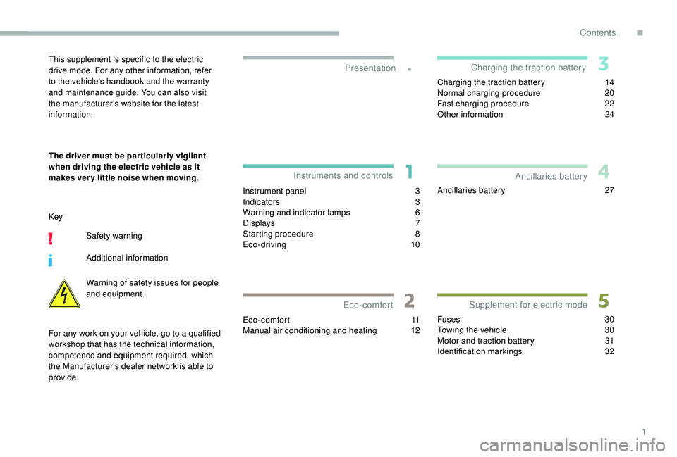
2Charging the traction battery
1
4
Normal charging procedure
2
0
Fast charging procedure
2
2
Other information
2
4
Ancillaries battery 2 7
Fuses
30
Towing the vehicle
3
0
Motor and traction battery
3
1
Identification markings
3
2
Presentation
Instruments and controls
Eco-comfort Charging the traction battery
Supplement for electric mode Ancillaries batteryThis supplement is specific to the electric
drive mode. For any other information, refer
to the vehicle's handbook and the warranty
and maintenance guide. You can also visit
the manufacturer's website for the latest
information.
The driver must be par ticularly vigilant
when driving the electric vehicle as it
makes ver y little noise when moving.
Key
Safety warning
Additional information
Warning of safety issues for people
and equipment.
For any work on your vehicle, go to a qualified
workshop that has the technical information,
competence and equipment required, which
the Manufacturer's dealer network is able to
provide.
Contents
.
Contents
Page 4 of 252
2
Electrical system
1.Normal charging socket
1. Normal charging socket
2. 300
Volt electrical system
3. 12
Volt ancillaries battery
4. Traction battery
5. Fast charging socket
Instruments and controls
1.Instrument panel
2. Display screens
3. Drive selector
Presentation
Page 5 of 252

3
Instrument panel
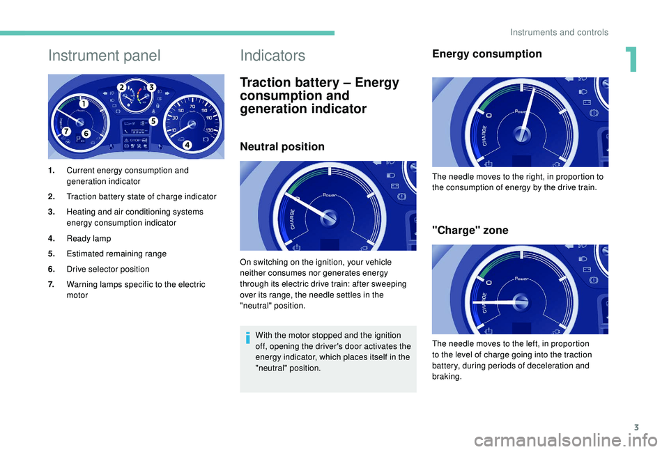
1.Current energy consumption and
generation indicator
2. Traction battery state of charge indicator
3. Heating and air conditioning systems
energy consumption indicator
4. Ready lamp
5. Estimated remaining range
6. Drive selector position
7. Warning lamps specific to the electric
motor
Indicators
Traction battery – Energy
consumption and
generation indicator
Neutral position
With the motor stopped and the ignition
off, opening the driver's door activates the
energy indicator, which places itself in the
"neutral" position.
Energy consumption
"Charge" zone
On switching on the ignition, your vehicle
neither consumes nor generates energy
through its electric drive train: after sweeping
over its range, the needle settles in the
"neutral" position. The needle moves to the right, in proportion to
the consumption of energy by the drive train.
The needle moves to the left, in proportion
to the level of charge going into the traction
battery, during periods of deceleration and
braking.
1
Instruments and controls
Page 6 of 252

4
"Optimum" zone
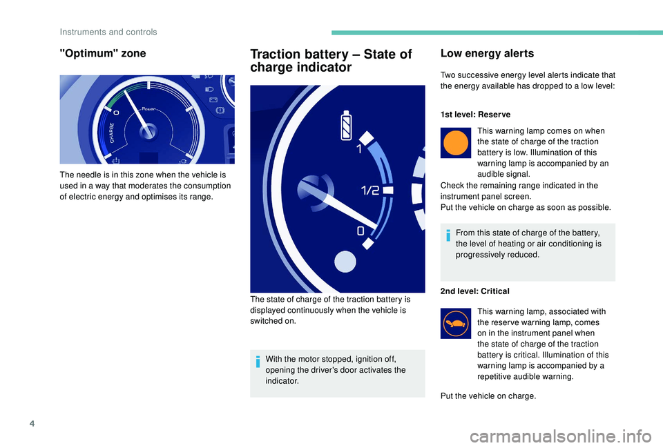
The needle is in this zone when the vehicle is
used in a way that moderates the consumption
of electric energy and optimises its range.
Traction battery – State of
charge indicator
With the motor stopped, ignition off,
opening the driver's door activates the
i n d i c a t o r.
The state of charge of the traction battery is
displayed continuously when the vehicle is
switched on.
Low energy alerts
Two successive energy level alerts indicate that
the energy available has dropped to a low level:
1st level: Reser ve
This warning lamp comes on when
the state of charge of the traction
battery is low. Illumination of this
warning lamp is accompanied by an
audible signal.
Check the remaining range indicated in the
instrument panel screen.
Put the vehicle on charge as soon as possible.
From this state of charge of the battery,
the level of heating or air conditioning is
progressively reduced.
2nd level: Critical This warning lamp, associated with
the reser ve warning lamp, comes
on in the instrument panel when
the state of charge of the traction
battery is critical. Illumination of this
warning lamp is accompanied by a
repetitive audible warning.
Put the vehicle on charge.
Instruments and controls
Page 9 of 252
7
Displays
Screen (depending on
equipment level)
Setting the units
Range
Each press of the button on the end of the
windscreen wiper stalk allows you to scroll
through the various trip computer information
displays, depending on the screen. The screen shows:
-
t
he estimated range remaining,
-
t
he additional range available by using
the ECO mode on the heating and air
conditioning control panel,
With navigation, the driving range area is
displayed on the map.
1
Instruments and controls
Page 10 of 252
8
Starting procedure
Starting the vehicle
- To start the vehicle, the drive selector must be in position P ,
-
p
ress the brake pedal,
-
t
urn the ignition key in the
switch.
Ready
This indicator lamp comes on when
the vehicle is ready to drive.
-
P
ress the brake pedal,
-
select R or D,
-
r
elease the brake pedal and press the
accelerator pedal to move off.
Instrument panel
The screen shows:
- a t rip distance recorder (choice of trip 1 or 2),
-
t
he average energy consumption from the
battery (over 62
miles (100 km)),
-
T
he average speed since the start of the
trip. This screen displays an estimated driving
range in miles or kilometres before the battery
has to be charged.
Trips (1 and 2)
Instruments and controls
Page 11 of 252

9
Parking the vehicle
When leaving the vehicle, it is strongly
recommended that you apply the parking
brake, place the drive selector in position P,
then switch off the ignition.
There is an audible signal on opening the
driver's door if:
-
t
he ignition is still on (" Ready" lamp on),
-
t
he vehicle has not been correctly
immobilised (drive selector not in
position P ).
An alert message is displayed in the screen.
Drive selector
P (Park). Parking. Move the selector
to position P , an audible signal will
sound.
If the drive selector is not in position P and/or if
the brake pedal is not pressed, the vehicle will
not start. Repeat the procedure for starting the
vehicle.
Selecting position D or R on the selector
determines the driving direction. It is preferable
to be at a complete stop before changing the
drive direction. The selection appears in the current energy
consumption screen in the instrument panel.
The driver must be particularly vigilant
when driving the electric vehicle as it
makes very little noise when moving. N (Neutral). Neutral. Move the
selector to position N , an audible
signal will sound.
Do not select this position, even momentarily,
when the vehicle is moving.
The vehicle is free-wheeling. Select D to return
to for ward drive. D (Drive). For ward drive. Move the
selector to position D , an audible
signal will sound. It is recommended to keep the brake pedal
pressed down to select positions R or D
.
R (Reverse). Reverse. Move the
selector to position R , an audible
signal will sound.
Only engage reverse when the vehicle is
immobilised.
When moving from position R to position P , N is
displayed momentarily in the instrument panel.
There is an audible signal when changing
drive position with the selector.
The audible signal is deactivated if the user has
chosen to inhibit operation of the "Rear parking
sensors".
1
Instruments and controls
Page 23 of 252

21
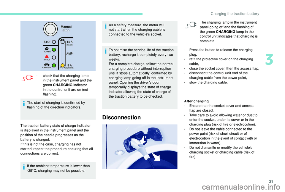
- check that the charging lamp in the instrument panel and the
green CHARGING indicator
in the control unit are on (not
flashing).
The start of charging is confirmed by
flashing of the direction indicators.
The traction battery state of charge indicator
is displayed in the instrument panel and the
position of the needle progresses as the
battery is charged.
If this is not the case, charging has not
started; repeat the procedure ensuring that all
connections are correct. If the ambient temperature is lower than
-25°C, charging may not be possible. As a safety measure, the motor will
not start when the charging cable is
connected to the vehicle's socket.
To optimise the ser vice life of the traction
battery, recharge it completely every two
weeks.
For a complete charge, follow the normal
charging procedure without interruption
until it stops automatically, confirmed by
charging lamp going off in the instrument
panel. Opening the driver's door
temporarily displays the state of charge
indicator allowing the state of charge of
the traction battery to be checked.
Disconnection
The charging lamp in the instrument
panel going off and the flashing of
the green CHARGING
lamp in the
control unit indicates that charging is
complete.
-
P
ress the button to release the charging
plug,
-
r
efit the protective cover on the charging
cable,
-
c
lose the socket cover, then the access flap,
-
d
isconnect the control unit end of the
charging cable from the power point,
-
s
tow the charging cable.
After charging
-
E
nsure that the socket cover and access
flap are closed.
-
T
ake care to avoid allowing water or dust to
enter the socket, under its cover or in the
charging plug (risk of fire or electrocution).
-
D
o not leave the cable connected to the
power point (risk of short circuit or of
electrocution in the event of contact with or
immersion in water).
-
D
o not dismantle or modify the vehicle's
charging socket or charging cable (risk of
f i r e).
3
Charging the traction battery