2017 PEUGEOT 5008 ECU
[x] Cancel search: ECUPage 174 of 404
172
The incorrect installation of a child seat in a
vehicle compromises the child's protection in
the event of an accident.
Check that there is no seat belt or seat belt
buckle under the child seat as this could
make it unstable.
Remember to fasten the seat belts or the
child seat harnesses keeping the slack
relative to the child's body to a minimum,
even for short journeys.
When installing a child seat using the seat
belt, ensure that the seat belt is tightened
correctly on the child seat and that it secures
the child seat firmly on the seat of your
vehicle. If your passenger seat is adjustable,
move it for wards if necessary.
At rear seating positions, always leave
sufficient space between the front seat and:
-
a "
rear ward facing" child seat,
-
t
he feet of a child seated in a "for ward
facing" child seat.
For this, move the seat for ward and, if
necessary, straighten its backrest too.
For optimal installation of the "forward facing"
child seat, verify that its backrest is as close
as possible to the backrest of the vehicle
seat, if possible in contact with it.
Advice
The head restraint must be removed before
installing a child seat with a backrest on a
passenger seat.
Ensure that the head restraint is stored or
attached securely to prevent it from being
thrown around the vehicle in the event of
sharp braking. Refit the head restraint once
the child seat has been removed. PEUGEOT recommends using a booster seat
with a backrest, equipped with a belt guide at
shoulder level.
As a safety precaution, do not leave:
-
a c
hild or children alone and unattended in
a vehicle,
-
a c
hild or an animal in a vehicle under the
sun, with the windows closed,
-
t
he keys within the reach of children inside
the vehicle.
To prevent accidental opening of the doors
and rear windows, use the child lock.
Take care not to open the rear windows by
more than one third.
To protect young children from the rays of the
sun, fit side blinds on the rear windows.
Children in front
The legislation on carrying children on the
front passenger seat is specific to each
country. Refer to the legislation in force in
your country.
Deactivate the passenger's front airbag when
a rear ward facing child seat is installed on the
front passenger seat.
Otherwise, the child risks being seriously
injured or killed if the airbag is deployed.
Installing a booster seat
The chest part of the seat belt must be
positioned on the child's shoulder without
touching the neck.
Ensure that the lap part of the seat belt
passes correctly over the child's thighs.
Safety
Page 217 of 404
215
The system is not intended for the
following situations:
-
i
f the front end of the vehicle has
been modified (addition of long-range
headlamps, painting of the front
bumper),
-
d
riving on a racing circuit,
-
r
unning on a rolling stand,
-
u
se of snow chains, non-slip covers or
studded tyres.
The use of mats not approved by
PEUGEOT may inter fere with the
operation of the cruise control.
To avoid any risk of jamming of the pedals:
-
e
nsure that mats are secured correctly,
-
n
ever place one mat on top of another.
Operating fault
In the event of a fault with the cruise
control, you are alerted by the
illumination of this warning lamp
and the display of a message in the
instrument panel, accompanied by
an audible signal.
Have the system checked by a PEUGEOT
dealer or a qualified workshop. Operation of the radar, located in the
front bumper, may be impaired by the
accumulation of dirt (dust, mud, etc.) or in
certain weather conditions (snow, frost,
e t c .) .
Clean the front bumper regularly.
If the front bumper is to be repainted or
retouched, contact a PEUGEOT dealer
or a qualified workshop. Certain types of
paint could inter fere with the operation of
the radar.
Distance alert and Active
Safety Brake
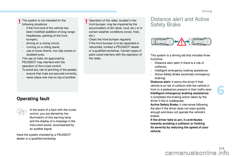
This system is a driving aid that includes three
functions:
-
D
istance alert (alert if there is a risk of
collision),
-
I
ntelligent emergency braking assistance,
-
A
ctive Safety Brake (automatic emergency
b r ak ing).
Distance alert: it warns the driver if their
vehicle is at risk of collision with the vehicle in
front or a pedestrian present in their traffic lane.
Intelligent emergency braking assistance:
it completes the braking action taken by the
driver if this is inadequate.
Active Safety Brake: it intervenes following
the alert if the driver does not react quickly
enough and does not operate the vehicle's
brakes.
If the driver fails to act, it contributes
towards avoiding a collision or limiting
its severity by reducing the speed of your
vehicle.
6
Driving
Page 250 of 404
248
Towing a trailer
Your vehicle is primarily designed for
transporting people and luggage, but it may
also be used for towing a trailer.We recommend the use of genuine
PEUGEOT towbars and their harnesses
that have been tested and approved from
the design stage of your vehicle, and that
the fitting of the towbar is entrusted to a
PEUGEOT dealer or a qualified workshop.
If the towbar is not fitted by a PEUGEOT
dealer, it must still be fitted in accordance
with the vehicle manufacturer's
instructions. Please respect the maximum authorised
towable weights, indicated on the
registration certificate or in your vehicle’s
technical data.
For more information on Weights
(and the
towed loads which apply to your vehicle)
refer to the corresponding section.
Vehicle equipped with motorised
tailgate with "Hands-Free Tailgate
Access" function
To avoid unwanted opening of the tailgate
when using the towing device:
-
p
lease deactivate the "Hands-Free
Tailgate Access" function in advance in
your vehicle's configuration menu,
-
o
r move the electronic key away from
the recognition zone, with the tailgate
closed.
Towbar with quickly
detachable towball
No tools are required to install or remove the
towball on this genuine towbar system.
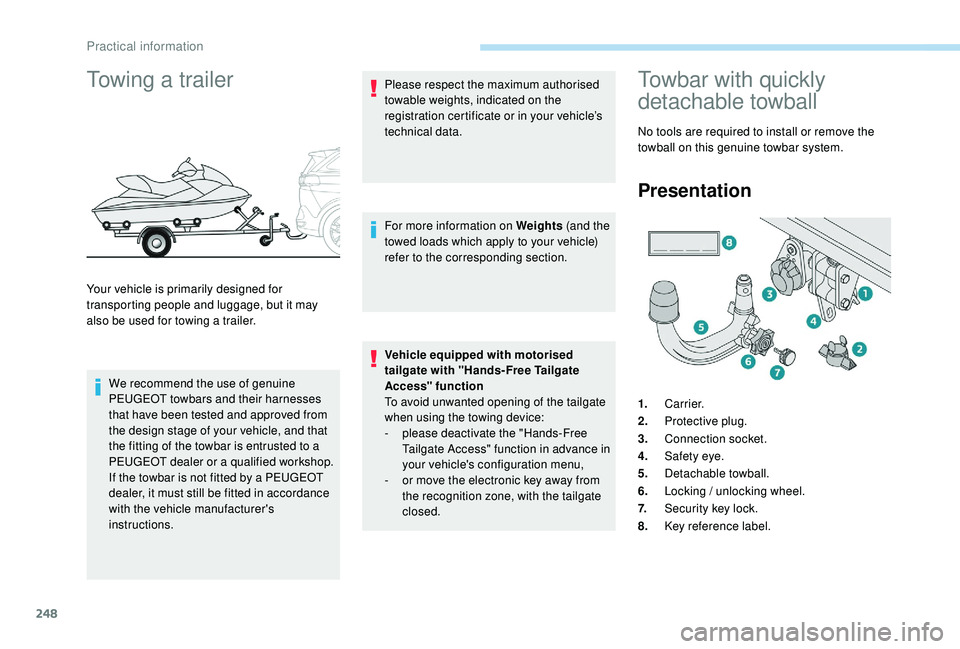
Presentation
1. Carrier.
2. Protective plug.
3. Connection socket.
4. Safety eye.
5. Detachable towball.
6. Locking / unlocking wheel.
7. Security key lock.
8. Key reference label.
Practical information
Page 251 of 404
249
Trailers with LED lamps are not
compatible with the wiring harness of this
device.
To know the technical features, and in
particular the towable weights for your
vehicle, refer to the corresponding section.
For advice on driving safely when To w i n g
a trailer , refer to the corresponding
section.
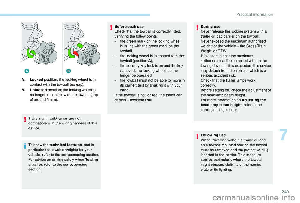
A.
Locked position; the locking wheel is in
contact with the towball (no gap).
B. Unlocked position; the locking wheel is
no longer in contact with the towball (gap
of around 5 mm). Before each use
Check that the towball is correctly fitted,
verifying the follow points:
-
t
he green mark on the locking wheel
is in line with the green mark on the
towball,
-
t
he locking wheel is in contact with the
towball (position A ),
-
t
he security key lock is on and the key
removed; the locking wheel can no
longer be operated,
-
t
he towball must not be able to move in
its carrier; test by shaking it with your
hand.
If the towball is not locked, the trailer can
detach – accident risk! During use
Never release the locking system with a
trailer or load carrier on the towball.
Never exceed the maximum authorised
weight for the vehicle – the Gross Train
Weight or GTW.
It is essential that the maximum
authorised load be complied with on the
towing device: if it is exceeded, this device
may detach from the vehicle, which is a
serious accident risk.
Check that the trailer lamps work
c o r r e c t l y.
Before setting off, check the adjustment of
the headlamp beam height.
For more information on Adjusting the
headlamp beam height
, refer to the
corresponding section.
Following use
When travelling without a trailer or load
on a towbar-mounted carrier, the towball
must be removed and the protective plug
inserted in the carrier. This measure
applies particularly where the towball
might obscure visibility of the number
plate or its lighting.
7
Practical information
Page 257 of 404
255
Fitting roof bars
As a safety measure and to avoid
damaging the roof, it is essential to use
the transverse bars approved for your
vehicle.
Obser ve the instructions on fitting and use
contained in the guide supplied with the
roof bars.
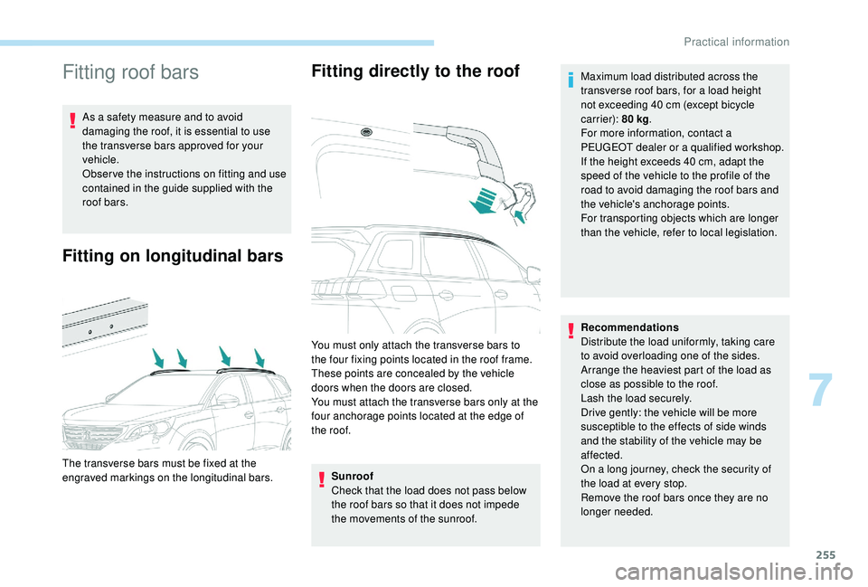
Fitting on longitudinal barsFitting directly to the roof
Sunroof
Check that the load does not pass below
the roof bars so that it does not impede
the movements of the sunroof.
The transverse bars must be fixed at the
engraved markings on the longitudinal bars. You must only attach the transverse bars to
the four fixing points located in the roof frame.
These points are concealed by the vehicle
doors when the doors are closed.
You must attach the transverse bars only at the
four anchorage points located at the edge of
the roof.
Recommendations
Distribute the load uniformly, taking care
to avoid overloading one of the sides.
Arrange the heaviest part of the load as
close as possible to the roof.
Lash the load securely.
Drive gently: the vehicle will be more
susceptible to the effects of side winds
and the stability of the vehicle may be
affected.
On a long journey, check the security of
the load at every stop.
Remove the roof bars once they are no
longer needed. Maximum load distributed across the
transverse roof bars, for a load height
not exceeding 40 cm (except bicycle
carrier): 80 kg
.
For more information, contact a
PEUGEOT dealer or a qualified workshop.
If the height exceeds 40 cm, adapt the
speed of the vehicle to the profile of the
road to avoid damaging the roof bars and
the vehicle's anchorage points.
For transporting objects which are longer
than the vehicle, refer to local legislation.
7
Practical information
Page 269 of 404
267
Engine 2.0 HDi
F Fill the fuel tank with at least five litres of Diesel.
F
O
pen the bonnet.
F
I
f necessary, unclip the cover to access the
priming pump.
F
L
oosen the degassing bolt.
F
U
se the priming pump until fuel appears in
the transparent tube.
F
R
etighten the degassing bolt.
F
O
perate the starter until the engine starts (if
the engine does not start at the first attempt,
wait around 15
seconds before trying
again).
F
I
f the engine does not start after a few
attempts, operate the priming pump again
then start the engine.
F
P
ut it back in place, clip in the cover and
ensure it is clipped in.
F
C
lose the boot again.
Tool kit
This is a set of tools provided with the vehicle.
Its content depends on your vehicle's
equipment:
-
t
emporary puncture repair kit,
-
spar
e wheel.
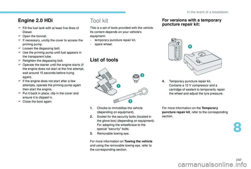
List of tools
1.Chocks to immobilise the vehicle
(depending on equipment).
2. Socket for the security bolts (located in
the glove box) (depending on equipment).
For adapting the wheelbrace to the
special "security" bolts.
3. Removable towing eye.
For more information on Towing the vehicle
and using the removable towing eye, refer to
the corresponding section.
For versions with a temporary
puncture repair kit:
For more information on the Temporary
puncture repair kit , refer to the corresponding
section. 4. Temporary puncture repair kit.
Contains a 12 V compressor and a
cartridge of sealant to temporarily repair
the wheel and adjust the tyre pressure.
8
In the event of a breakdown
Page 272 of 404
270
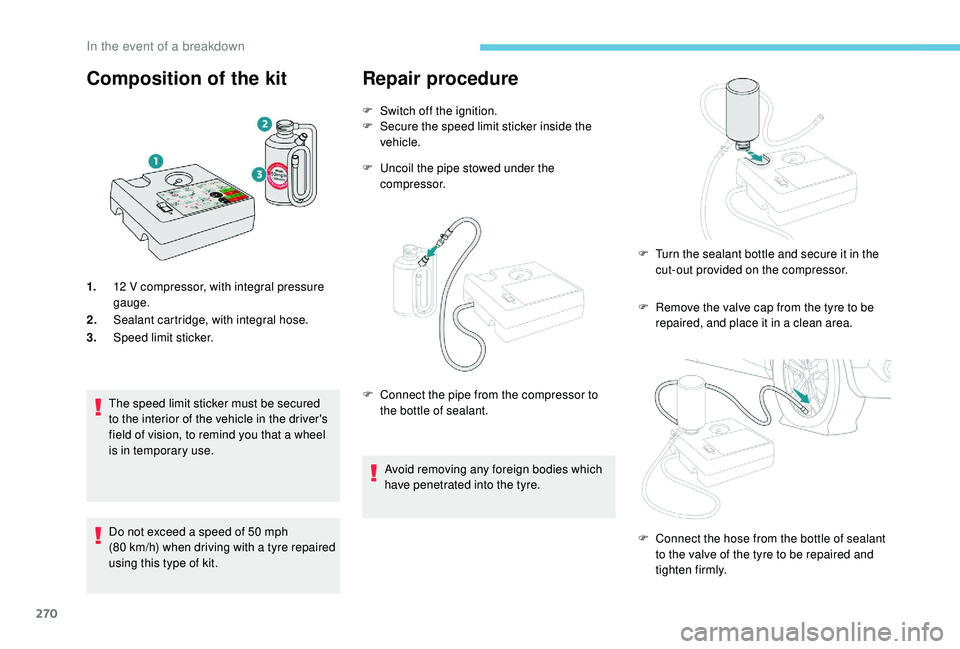
Composition of the kit
1.12 V compressor, with integral pressure
gauge.
2. Sealant cartridge, with integral hose.
3. Speed limit sticker.
The speed limit sticker must be secured
to the interior of the vehicle in the driver's
field of vision, to remind you that a wheel
is in temporary use.
Do not exceed a speed of 50
mph
(80
km/h) when driving with a tyre repaired
using this type of kit.
Repair procedure
F Switch off the ignition.
F S ecure the speed limit sticker inside the
vehicle.
F
U
ncoil the pipe stowed under the
compressor.
F
R
emove the valve cap from the tyre to be
repaired, and place it in a clean area.
F
C
onnect the pipe from the compressor to
the bottle of sealant.
Avoid removing any foreign bodies which
have penetrated into the tyre. F
T
urn the sealant bottle and secure it in the
cut-out provided on the compressor.
F
C
onnect the hose from the bottle of sealant
to the valve of the tyre to be repaired and
tighten firmly.
In the event of a breakdown
Page 278 of 404
276
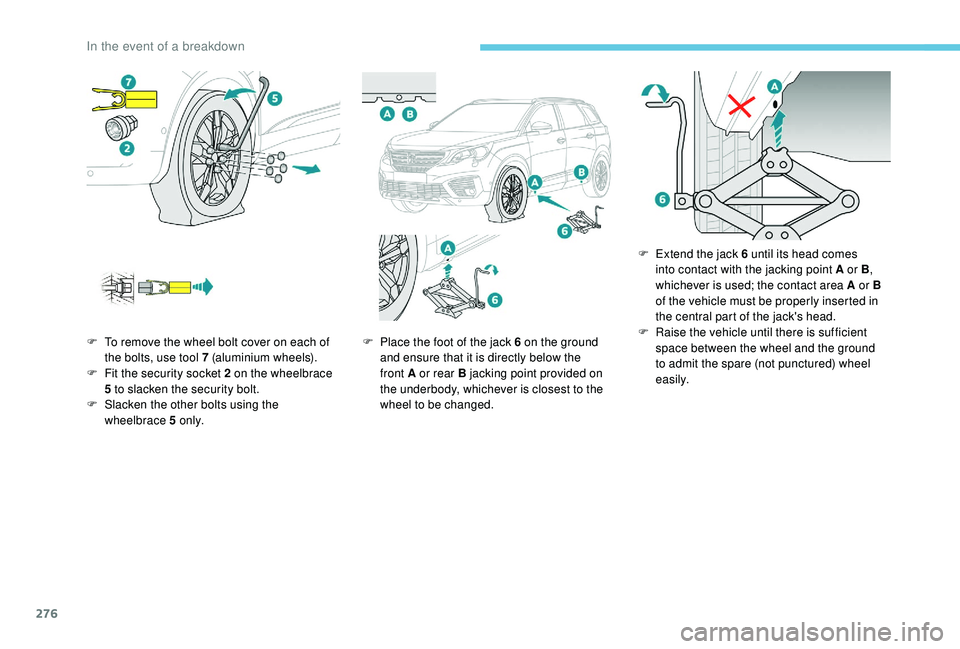
F To remove the wheel bolt cover on each of the bolts, use tool 7 (aluminium wheels).
F
F
it the security socket 2 on the wheelbrace
5
to slacken the security bolt.
F
S
lacken the other bolts using the
wheelbrace 5
o n l y. F
P lace the foot of the jack 6 on the ground
and ensure that it is directly below the
front A or rear B jacking point provided on
the underbody, whichever is closest to the
wheel to be changed. F
E
xtend the jack 6 until its head comes
into contact with the jacking point A or B ,
whichever is used; the contact area A or B
of the vehicle must be properly inserted in
the central part of the jack's head.
F Ra ise the vehicle until there is sufficient
space between the wheel and the ground
to admit the spare (not punctured) wheel
easily.
In the event of a breakdown