Page 181 of 368

179
4008_en_Chap07_info-pratiques_ed01-2016
Fitting roof bars
the transverse roof bars are fitted to the longitudinal bars at the 8 fixing points masked by covers.using a small screwdriver, remove the 8 covers on the inner faces of the longitudinal bars.
th
e transverse bars are fitted directly to the roof of the vehicle, at the 4 anchorage points masked
by covers.
Slide the covers towards the front of the vehicle to remove them.
Retain the protective covers.
After removing the roof bars, the protective covers should be refitted:
F
i
nsert the fixing tongues into the apertures then slide the covers towards the rear of the vehicle.
th
e body sill finishers should not be
used as a step when fitting roof bars.
us
e accessories recommended by
P
e
uge
Ot
and follow the accessory
manufacturer's fitting instructions.
Maximum authorised weight on the roof
bars, for a loading height not exceeding
40 cm (except bicycle carriers): 80 kg.
If the height exceeds 40 cm, adapt the
speed of the vehicle to the condition of
the road, to avoid damaging the roof
bars and the fixings on the roof.
Please refer to national legislation to
comply with the regulations regarding
the transportation of objects which are
longer than the vehicle.
For reasons of safety and to avoid damaging the roof, it is essential to use transverse bars that are
approved for your vehicle.
Vehicles fitted with longitudinal bars
Vehicles not fitted with longitudinal bars
7
Practical information
Page 190 of 368

188
4008_en_Chap07_info-pratiques_ed01-2016
Brake wear depends on the style
of driving, particularly in the case
of vehicles used in town, over short
distances. It may be necessary to have
the condition of the brakes checked,
even between vehicle services.
Brake pads
For information on checking brake
disc wear, contact a PeugeOt
dealer or a qualified workshop.
Brake disc wear Parking brake
If excessive travel or a loss of
effectiveness of this system is
noticed, the parking brake must be
checked, even between two services.
Only use products recommended by
P
e
uge
Ot
or products of equivalent
quality and specification.
In order to optimise the operation of
units as important as those in the
braking system, P
e
uge
Ot
selects and
offers very specific products.
After washing the vehicle, dampness,
or in wintry conditions, ice can form
on the brake discs and pads: braking
efficiency may be reduced. Make light
brake applications to dry and defrost
the brakes.
Checking this system must be done by a
P
e
uge
Ot
dealer or a qualified workshop.
un
less there is a leak in the circuit, a drop in
the brake fluid level indicates that the brake
pads are worn.
Practical information
Page 194 of 368

192
4008_en_Chap08_en-cas-de panne_ed01-2016
F If the specified pressure has not been
reached after about 10 minutes, this means
that the tyre is not repairable; contact a
P
e
uge
Ot
dealer or a qualified workshop
for roadside assistance.
F
R
emove the compressor and stow the kit.Do not operate the compressor for more
than 10 minutes continuously.
If the compressor seems extremely
hot, switch it off and disconnect it
immediately. Leave it to cool for at least
30 minutes.
As soon as possible after a repair using
the kit, go to a P
e
uge
Ot
dealer or a
qualified workshop.
Make sure that you tell the technician
that you have used the kit. After
checking, the technician will advise you
whether the tyre can be repaired or if it
must be replaced.
If the vehicle is fitted with under-
inflation detection, the under-inflation
warning lamp remains on until the
system has been reinitialised.
For more information on Under-
inflation detection
, refer to the
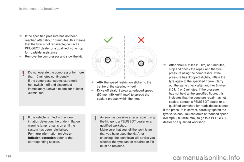
corresponding section. F
A
ffix the speed restriction sticker to the
centre of the steering wheel.
F
D
rive off straight away at reduced speed
(50 mph (80 km/h) max) to spread the
sealant product within the tyre. F
A
fter about 6 miles (10 km) or 5 minutes,
stop and check the repair and the tyre
pressure using the compressor. If the
pressure has dropped slightly, inflate the
tyre again to the specified figure. Carry
out the same check after another 6 miles
(10
km) or 5 minutes: if the pressure
has not held at the specified figure, this
indicates that the puncture repair has not
sealed; contact a P
e
uge
Ot
dealer or a
qualified workshop for roadside assistance.
If the pressure is correct, carefully tighten the
tyre valve cap. You can drive at reduced speed
(50 mph (80 km/h) max) to go to a P
e
uge
Ot
dealer or a qualified workshop.
In the event of a breakdown
Page 195 of 368

193
4008_en_Chap08_en-cas-de panne_ed01-2016
Changing a wheel
the tools are stowed in the boot under the
f l o o r.
to g
ain access to them:
F
O
pen the boot.
F
L
ift and remove the boot floor.
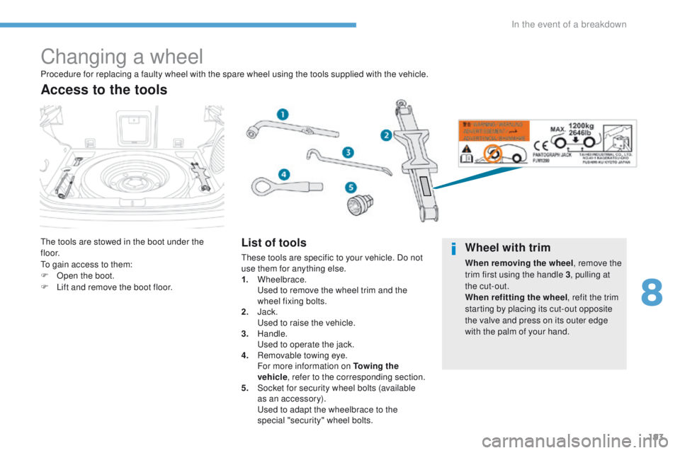
Access to the tools
List of tools
these tools are specific to your vehicle. Do not
use them for anything else.
1.
Wheelbrace.
u
s
ed to remove the wheel trim and the
wheel fixing bolts.
2.
J
ack.
u
se
d to raise the vehicle.
3.
Handle.
u
s
ed to operate the jack.
4.
R
emovable towing eye.
F
or more information on To w i n g the
vehicle , refer to the corresponding section.
5.
S
ocket for security wheel bolts (available
as an accessory).
u
s
ed to adapt the wheelbrace to the
special "security" wheel bolts.
Procedure for replacing a faulty wheel with the spare wheel using the tools supplied with the vehicle.Wheel with trim
When removing the wheel
, remove the
trim first using the handle 3 , pulling at
the cut-out.
When refitting the wheel , refit the trim
starting by placing its cut-out opposite
the valve and press on its outer edge
with the palm of your hand.
8
In the event of a breakdown
Page 196 of 368
194
4008_en_Chap08_en-cas-de panne_ed01-2016
the spare wheel is installed in the boot under
t h e f l o o r.
Depending on version, the spare wheel may be
a standard size steel or alloy wheel, or for some
countries it is the "space saver" type.
For access to the spare wheel, see "Access to
t he to o ls".
Access to the spare wheel
Taking out the standard wheel
F unscrew the central bolt A .
F R aise the spare wheel towards you from
the rear.
F
t
a
ke the wheel out of the boot.
Putting the standard wheel
back in place
F Put the wheel back in its housing.
F P ut the central bolt A in place in the centre
of the wheel.
F
t
i
ghten fully to retain the wheel correctly.
In the event of a breakdown
Page 200 of 368
198
4008_en_Chap08_en-cas-de panne_ed01-2016
F Lower the vehicle fully.
F
F old the jack 2 and remove it. F
L ock the anti-theft bolt using the
wheelbrace 1 fitted with the anti-theft
socket 5 (if your vehicle has one).
F
L
ock the other bolts using only the
wheelbrace 1 .
F
S
tow the tools (for more information, refer
to the corresponding section).
In the event of a breakdown
Page 201 of 368

199
4008_en_Chap08_en-cas-de panne_ed01-2016
Changing a bulb
For bulbs that have alignment lugs
(H1, H7...) ensure that they are
fitted correctly for the best lighting
performance.
th
e headlamps have polycarbonate
lenses with a protective coating:
F
d
o not clean them using a dr y
or abrasive cloth, nor with a
detergent or solvent product,
F
u
se a sponge and soapy water,
F
w
hen using a high pressure washer
on persistent marks, do not keep
the lance directed towards the
lamps or their edges for too long,
so as not to damage their protective
coating and seals.
F
D
o not touch the bulb directly with
your fingers, use lint-free cloths.
Changing a bulb should only be done
after the headlamp has been switched
off for several minutes (risk of serious
burns).
It is imperative to use only anti-
ultraviolet (
uV
) type bulbs in order not
to damage the headlamp.
Always replace a failed bulb with a
new bulb with the same type and
specification.
Risk of electrocution
Replacement of the xenon bulbs
(D1S-35W) must be carried out by
a P
e
uge
Ot
dealer or a qualified
workshop.
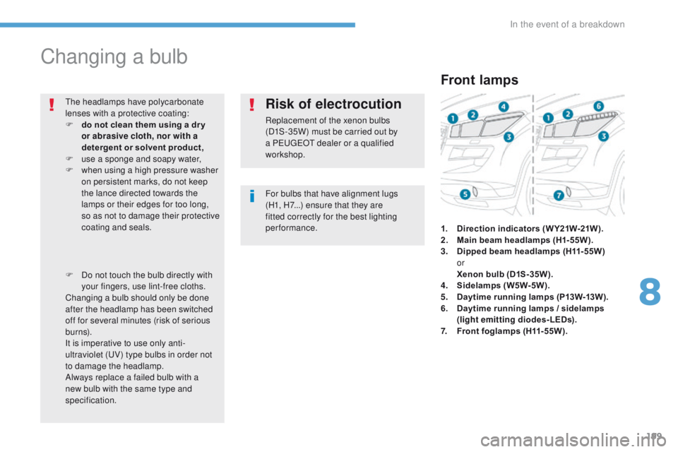
Front lamps
1. Direction indicators ( W Y21W-21W ).
2. M ain beam headlamps (H1-55W).
3.
D
ipped beam headlamps (H11-55W)
or
Xe
non bulb (D1S-35W).
4.
S
idelamps (W5W-5W).
5.
D
aytime running lamps (P13W-13W).
6.
D
aytime running lamps / sidelamps
(light emitting diodes-LEDs).
7.
F
ront foglamps (H11-55W).
8
In the event of a breakdown
Page 204 of 368
202
4008_en_Chap08_en-cas-de panne_ed01-2016
F Push the repeater towards the rear to disengage it.
F
D isconnect the repeater connector.
F
C
hange the repeater unit.
to
reassemble, carry out these operations in reverse order.
Contact a P
e
uge
Ot
dealer or a qualified workshop to obtain replacement repeaters.
Changing direction indicator side repeaters
Door mirror spotlamps
You should contact a Pe ugeOt dealer or a qualified workshop for the replacement of the light
emitting diode - LeD .
In the event of a breakdown