2017 OPEL ZAFIRA C clock
[x] Cancel search: clockPage 75 of 289

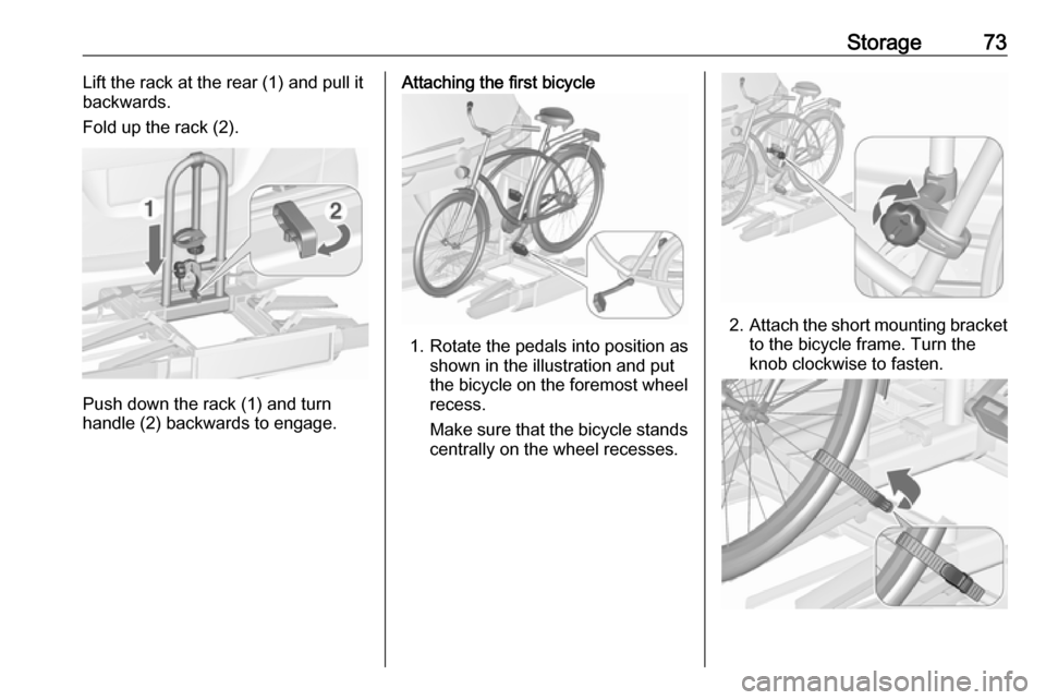
Storage73Lift the rack at the rear (1) and pull it
backwards.
Fold up the rack (2).
Push down the rack (1) and turn
handle (2) backwards to engage.
Attaching the first bicycle
1. Rotate the pedals into position as shown in the illustration and put
the bicycle on the foremost wheel
recess.
Make sure that the bicycle stands centrally on the wheel recesses.
2. Attach the short mounting bracket
to the bicycle frame. Turn the
knob clockwise to fasten.
Page 78 of 289

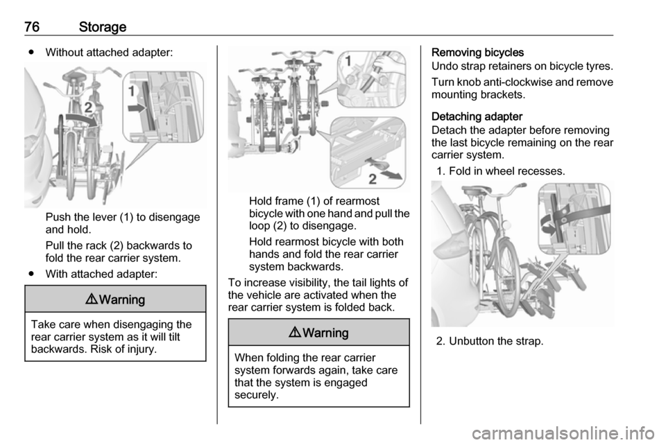
76Storage● Without attached adapter:
Push the lever (1) to disengage
and hold.
Pull the rack (2) backwards to
fold the rear carrier system.
● With attached adapter:
9 Warning
Take care when disengaging the
rear carrier system as it will tilt
backwards. Risk of injury.
Hold frame (1) of rearmost
bicycle with one hand and pull the
loop (2) to disengage.
Hold rearmost bicycle with both
hands and fold the rear carrier
system backwards.
To increase visibility, the tail lights of
the vehicle are activated when the
rear carrier system is folded back.
9 Warning
When folding the rear carrier
system forwards again, take care
that the system is engaged
securely.
Removing bicycles
Undo strap retainers on bicycle tyres.
Turn knob anti-clockwise and remove
mounting brackets.
Detaching adapter
Detach the adapter before removing
the last bicycle remaining on the rear
carrier system.
1. Fold in wheel recesses.
2. Unbutton the strap.
Page 92 of 289

90StoragePartitioning net in front of tailgate
Install directly in front of the tailgate.
Before installation push in the four
end pieces of the net rod by rotating
each end piece anticlockwise.
To install, push the net rods together
and insert into the openings of the
tailgate frame. The longer rod must
be inserted at the top.
To remove, push the net rods
together and remove.
Safety net
The safety net can be installed behind the seats of the second row or the
front seats.
Passengers must not be transported
behind the safety net.
Installation behind second row
seats
● There are installation openings on both sides in the roof frame
above second row seats:
suspend and engage rod of net at
one side, compress rod and
suspend and engage at the other side.
● Attach hooks of safety net straps
to front lashing eyes on both
sides in the load compartment.
● Tension both straps by pulling at the loose end.
Page 98 of 289

96Instruments and controlsInstruments and
controlsControls ....................................... 97
Steering wheel adjustment ........97
Steering wheel controls .............97
Heated steering wheel ...............97
Horn ........................................... 98
Windscreen wiper/washer .........98
Rear window wiper/washer .....100
Outside temperature ................100
Clock ....................................... 101
Power outlets ........................... 102
Cigarette lighter .......................103
Ashtrays .................................. 103
Warning lights, gauges and indi‐ cators ......................................... 104
Instrument cluster ....................104
Speedometer ........................... 104
Odometer ................................ 104
Trip odometer .......................... 104
Tachometer ............................. 105
Fuel gauge .............................. 105
Fuel selector ............................ 106
Engine coolant temperature gauge ..................................... 107
Service display ........................ 107Control indicators ....................108
Turn signal ............................... 110
Seat belt reminder ...................111
Airbag and belt tensioners .......111
Airbag deactivation ..................112
Charging system .....................112
Malfunction indicator light ........112
Brake and clutch system .........112
Operate pedal .......................... 113
Electric parking brake ..............113
Electric parking brake fault ......113
Antilock brake system (ABS) ...113
Gear shifting ............................ 114
Power steering ........................ 114
Following distance ...................114
Lane departure warning ..........114
Electronic Stability Control off . 114
Electronic Stability Control and Traction Control system .........114
Traction Control system off .....114
Preheating ............................... 115
Diesel particle filter ..................115
AdBlue ..................................... 115
Tyre pressure monitoring system .................................... 115
Engine oil pressure ..................115
Low fuel ................................... 116
Immobiliser .............................. 116
Exterior light ............................ 116
High beam ............................... 116High beam assist.....................116
LED headlights ........................ 116
Fog light ................................... 116
Rear fog light ........................... 116
Cruise control .......................... 116
Adaptive cruise control ............117
Vehicle detected ahead ...........117
Speed limiter ........................... 117
Traffic sign assistant ................117
Door open ................................ 117
Information displays ...................117
Driver Information Centre ........117
Info display .............................. 121
Vehicle messages ......................123
Warning chimes .......................124
Battery voltage ........................ 124
Vehicle personalisation ..............125
Telematics service .....................128
OnStar ..................................... 128
Page 103 of 289

Instruments and controls101
Grafic shows Navi 950 display.
A drop in temperature is indicated immediately and a rise in temperature
after a time delay.
If outside temperature drops to 3 °C,
a warning message is displayed in the Driver Information Centre.9 Warning
The road surface may already be
icy even though the display
indicates a few degrees above
0 °C.
Clock
Date and time are shown in the
Info-Display.
Depending on the vehicle
configuration the
● R 4.0 IntelliLink display or
● Navi 950 display
is available.
R 4.0 IntelliLink Press ; and then select Settings.
Select Time and Date to display the
respective submenu.
Set Time Format
To select the desired time format,
touch the screen buttons 12 h or 24 h .
Set Date Format To select the desired date format,
select Set Date Format and choose
between the available options in the
submenu.
Auto Set
To choose whether time and date are
to be set automatically or manually,
select Auto Set .
For time and date to be set
automatically, select On - RDS.
Page 137 of 289

Lighting135Headlights when driving
abroad
The asymmetrical headlight beam
extends visibility at the edge of the
road at the passenger side.
However, when driving in countries
where traffic drives on the opposite
side of the road, adjust the headlights to prevent dazzling of oncoming
traffic.
Vehicles with halogen headlight
There is a white adjuster element on
the rear of each headlight housing.
Turn adjuster element on each
headlight housing 1
/2 turn with a
size six hexagon key anticlockwise to set to right-hand traffic mode. To
adjust, insert the key in the guide as
shown in the illustration. Alternatively,
a Phillips head screwdriver
size three can be used for setting.
To reset to left-hand traffic mode, turn
adjuster elements on both headlight
housings 1
/2 turn clockwise.
Vehicles with LED headlight
1. Key in ignition switch.
2. Pull turn signal lever and hold (headlight flash).
3. Switch on ignition.
4. After approx. five seconds the control indicator f starts flashing
and an acoustic signal sounds.
Control indicator f 3 116.
Every time the ignition is switched on,
f flashes as a reminder for approx.
four seconds.
For deactivation, operate the same
procedure as described above. f will
not flash when function is
deactivated.
Daytime running lights Daytime running light increases
visibility of the vehicle during daylight.
They are switched on automatically
when the engine is running.
The system switches between
daytime running lights and headlights automatically, depending on the
lighting conditions. Automatic light
control 3 133.
Page 163 of 289

Driving and operating1611. Continuously drive the vehiclefor 10 minutes making sure that
vehicle speed is always higher
than 20 km/h.
2. If AdBlue refill is detected successfully, AdBlue supply-
driven limitations will disappear.
If AdBlue refill is still not detected,
seek the assistance of a workshop.
If AdBlue must be refilled at
temperatures below -11 °C, the
refilling of AdBlue may not be
detected by the system. In this
event, park the vehicle in a space
with a higher ambient temperature
until AdBlue is liquefied.
Note
When unscrewing the protective cap
from the filler neck, ammonia fumes
may emerge. Do not inhale as the fumes have a pungent smell. The
fumes are not harmful by inhalation.
The AdBlue tank should be filled
completely. This must be done if the
warning message regarding
prevention of an engine restart is
already displayed.The vehicle must be parked on a level surface.
The filler neck for AdBlue is located
behind the fuel filler flap, which is located at right rear side of the
vehicle.
The fuel filler flap can only be opened
if the vehicle is unlocked.
1. Remove key from ignition switch.
2. Close all doors to avoid ammonia fumes entering the interior of the
vehicle.
3. Release the fuel filler flap by pushing the flap 3 202.
4. Unscrew protective cap from the
filler neck.
5. Open AdBlue canister.
6. Mount one end of the hose on the
canister and screw the other end
on the filler neck.
7. Lift the canister until it is empty, or
until the flow from the canister has stopped. This can take up to five
minutes.
8. Place the canister on the ground to empty the hose, wait 15
seconds.
9. Unscrew the hose from the filler neck.
10. Mount the protective cap and turn
clockwise until it engages.
Note
Dispose of AdBlue canister
according to environmental
requirements. Hose can be reused
after flushing with clear water before
AdBlue dries out.
Page 205 of 289

Driving and operating203
The fuel filler flap can only be opened
if the vehicle is unlocked. Release the
fuel filler flap by pushing the flap.
Petrol and Diesel refuelling To open, turn the cap slowly
anticlockwise.The fuel filler cap can be retained in
the bracket on the fuel filler flap.
To refuel, fully insert the pump nozzle
and switch it on.
After the automatic cut-off, the tank can be topped up by operating the
pump nozzle a maximum of two more
times.
Caution
Wipe off any overflowing fuel
immediately.
To close, turn the fuel filler cap
clockwise until it clicks.
Close the flap and allow it to engage.
Vehicles with misfuel inhibitor9 Warning
Do not try to open the flap of the
fuel filler neck manually on
vehicles with misfuel inhibitor.
Disregarding this could lead to
trapping of the fingers.
Vehicles with a selective catalytic
reduction system are equipped with a
misfuel inhibitor.