Page 335 of 404

5. If the fuse is open�C, replace it with an
equivalent good fuse
�D.
6. Push the fuse box cover to install.
If a new fuse also opens, have the electrical
system checked and repaired. It is recommended
that you visit a NISSAN dealer for this service.Extended storage switch
If any electrical equipment does not operate,
remove the extended storage switch and check
for an open fuse.
NOTE:
The extended storage switch is used for
long term vehicle storage. Even if the ex-
tended storage switch is broken it is not
necessary to replace it. Replace only the
open fuse in the switch with a new fuse. How to replace the extended storage switch:
1. To remove the extended storage switch, be sure the ignition switch is in the OFF or
LOCK position.
2. Be sure the headlight switch is in the OFF position.
3. Remove the fuse box cover.
4. Pinch the locking tabs
�Aand�Bfound on
each side of the storage switch.
5. Pull the storage switch straight out from the fuse box
�C.
LDI2713LDI2747
8-20Do-it-yourself
Page 339 of 404
Note:
Changes or modifications not expressly ap-
proved by the party responsible for compli-
ance could void the user’s authority to op-
erate the equipment.
For Canada:
This device complies with Industry Canada
licence-exempt RSS standard(s) . Opera-
tion is subject to the following two condi-
tions: (1) this device may not cause inter-
ference, and (2) this device must accept any
interference, including interference that
may cause undesired operation of the de-
vice.HEADLIGHTS
For additional information on headlight bulb re-
placement, refer to the instructions outlined in
this section.
Replacing the halogen headlight bulb
The headlight is a semi-sealed beam type which
uses a replaceable headlight (halogen) bulb.
They can be replaced from inside the engine
compartment without removing the headlight as-
sembly.
JVM0002X
LIGHTS
8-24Do-it-yourself
Page 340 of 404

CAUTION
●High-pressure halogen gas is sealed in-
side the bulb. The bulb may break if the
glass envelope is scratched or the bulb
is dropped.
● Aiming should not be necessary after
replacing the H4 bulb. When aiming ad-
justment is necessary, it is recom-
mended that you visit a NISSAN dealer
for this service.
● Do not leave the headlight assembly
open without a bulb installed for a long
period of time. Dust, moisture, smoke,
etc. entering the headlight body may
affect bulb performance. Remove the
bulb from the headlight assembly just
before a replacement bulb is installed.
● Only touch the base when handling the
bulb. Never touch the glass envelope.
Touching the glass could significantly
affect bulb life and/or headlight
performance.
● Use the same number and wattage as
shown in the chart.
1. Disconnect the battery negative cable.
2. Disconnect the electrical connector
�Afrom
the rear end of the bulb. 3. Pull off the rubber cap
�B.
4. Push and turn the retaining pin
�Cto loosen
it.
5. Remove the headlight bulb. Do not shake or rotate the bulb when removing it.
6. Install the new bulb in the reverse order of removal.
Fog may temporarily form inside the lens of the
exterior lights in the rain or in a car wash. A
temperature difference between the inside and
the outside of the lens causes the fog. This is not
a malfunction. If large drops of water collect
inside the lens, it is recommended that you visit a
NISSAN dealer for servicing.
FOG LIGHTS (if so equipped)
For additional information on fog light bulb re-
placement, refer to the instructions outlined in
this section.
Replacing the fog light bulb
If fog light bulb replacement is required, it is
recommended that you visit a NISSAN dealer for
this service.
CAUTION
● High pressure halogen gas is sealed
inside the halogen bulb. The bulb may
break if the glass envelope is scratched
or the bulb is dropped.
● When handling the bulb, do not touch
the glass envelope.
● Use the same number and wattage as
originally installed as shown in the
chart.
● Do not leave the bulb out of the fog light
for a long period of time as dust, mois-
ture and smoke may enter the fog light
body and affect the performance of the
fog light.
Do-it-yourself8-25
Page 341 of 404
EXTERIOR AND INTERIOR LIGHTS
ItemWattage (W)Bulb No.
Headlight assembly High/Low (Halogen) 60/55HB2
Turn/Position 28/83457A
Side marker 5W5W
Fog light (if so equipped) 55H11
Door mirror turn signal light (if so equipped)* ——
Room light 8—
Map light (if so equipped) 5W5W
Trunk compartment light 3.4158
High-mounted stop light* Inside (if so equipped) 16W16W
Spoiler (if so equipped) ——
Rear combination light* Turn signal light 21PY21W
Stop/Tail 21/5P21/5W
Backup (reversing) 21P21W
License plate light* 5W5W
Always check with the Parts Department at a NISSAN dealer for the latest parts information.
* It is recommended that you visit a NISSAN dealer for replacement.
8-26Do-it-yourself
Page 342 of 404
1. Map lights (if so equipped)
2. Room light
3. Door mirror turn signal light(if so equipped)
4. Headlight assembly
5. Fog light (if so equipped)
6. High-mounted stop light (spoiler)
(if so equipped)
7. License plate light
8. Trunk light
9. High-mounted stop light (inside)
(if so equipped)
10. Rear combination light
LDI2793
Do-it-yourself8-27
Page 343 of 404
Replacement procedures
All other lights are either type A, B, C or D. When
replacing a bulb, first remove the lens, lamp
and/or cover.
Indicates bulb removal
Indicates bulb installationUse a cloth to protect the housing.
SDI1805
Map lights (if so equipped)
LDI2044
Trunk light
WDI0343
8-28Do-it-yourself
Page 344 of 404
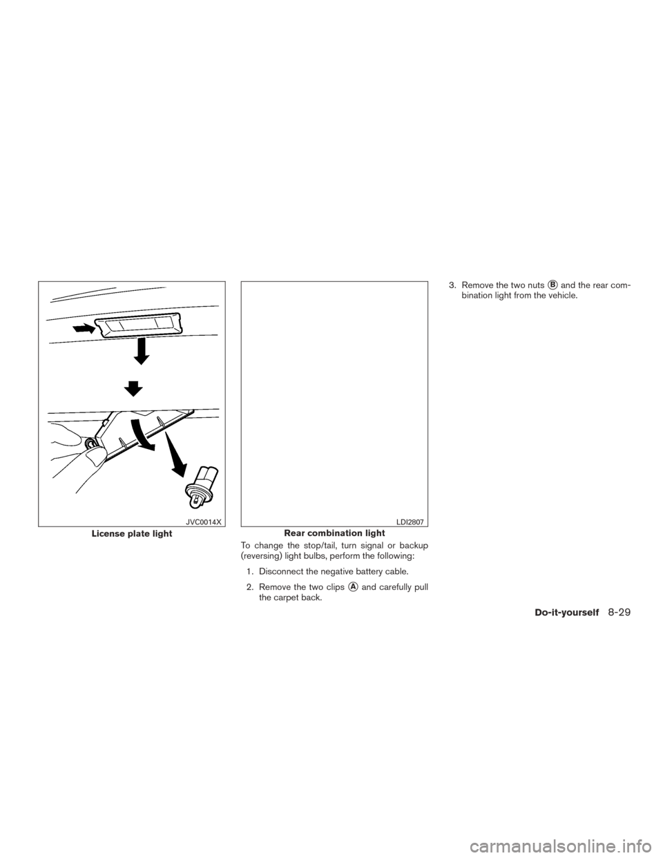
To change the stop/tail, turn signal or backup
(reversing) light bulbs, perform the following:1. Disconnect the negative battery cable.
2. Remove the two clips
�Aand carefully pull
the carpet back. 3. Remove the two nuts
�Band the rear com-
bination light from the vehicle.
License plate light
JVC0014X
Rear combination light
LDI2807
Do-it-yourself8-29
Page 345 of 404

4. Disconnect the electrical connector�Cfrom
the rear combination light.
5. Remove four screws
�Dand the housing
from the rear combination light.
6. Replace the necessary bulbs.
Follow the instruction in reverse order to install
the rear combination light and carpet. If you have a flat tire, refer “Flat tire” in the
“In case of emergency” section of this
manual.
TIRE PRESSURE
Tire Pressure Monitoring System (TPMS)
This vehicle is equipped with the Tire
Pressure Monitoring System (TPMS) . It
monitors tire pressure of all tires except
the spare. When the low tire pressure
warning light is lit and the CHECK TIRE
PRES warning is displayed in the odom-
eter, one or more of your tires is signifi-
cantly under-inflated.
The TPMS will activate only when the
vehicle is driven at speeds above 16 mph
(25 km/h). Also, this system may not de-
tect a sudden drop in tire pressure (for
example a flat tire while driving) .
For additional information, refer to “Low
tire pressure warning light” in the “Instru-
ments and controls” section, “Tire Pres-
sure Monitoring System (TPMS)” in the
“Starting and driving” section, and “Flat
tire” in the “In case of emergency” section
of this manual.
Tire inflation pressure
Check the tire pressures (including the spare)
often and always prior to long distance trips. The
recommended tire pressure specifications are
shown on the F.M.V.S.S./C.M.V.S.S. certification
label or the Tire and Loading Information label
under the “Cold Tire Pressure” heading. The Tire
and Loading Information label is affixed to the
driver side center pillar. Tire pressures should be
checked regularly because:
● Most tires naturally lose air over time.
● Tires can lose air suddenly when driven over
potholes or other objects or if the vehicle
strikes a curb while parking.
The tire pressures should be checked when the
tires are cold. The tires are considered COLD
after the vehicle has been parked for 3 or more
hours, or driven less than 1 mile (1.6 km) at
moderate speeds.
LDI2808
WHEELS AND TIRES
8-30Do-it-yourself

Bulb No.
Headlight assembly High/Low (Halogen) 60/55HB2
Turn/Position 28/83457A
Side marker 5W5W
Fog light (if so equipped) 55H11
Door mirror turn signal li")

2. Room light
3. Door mirror turn signal light(if so equipped)
4. Headlight assembly
5. Fog light (if so equipped)
6. High-mounted stop light (spoiler)
(if so equipped)")