Page 156 of 671
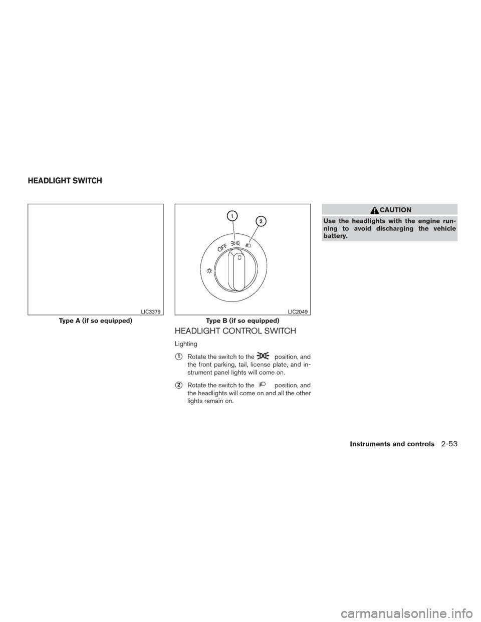
HEADLIGHT CONTROL SWITCH
Lighting
�1Rotate the switch to theposition, and
the front parking, tail, license plate, and in-
strument panel lights will come on.
�2Rotate the switch to theposition, and
the headlights will come on and all the other
lights remain on.
CAUTION
Use the headlights with the engine run-
ning to avoid discharging the vehicle
battery.
Type A (if so equipped)
LIC3379
Type B (if so equipped)
LIC2049
HEADLIGHT SWITCH
Instruments and controls2-53
Page 157 of 671

The autolight system allows the headlights to be
set so they turn on and off automatically. The
autolight system can:● Turn on the headlights, front parking, tail,")
Autolight system (if so equipped)
The autolight system allows the headlights to be
set so they turn on and off automatically. The
autolight system can:● Turn on the headlights, front parking, tail,
license plate and instrument panel lights au-
tomatically when it is dark.
● Turn off all the lights when it is light.
● Keep all the lights on for a period of time after
you place the ignition switch in the OFF
position and all doors are closed. NOTE:
Autolight activation sensitivity and the time
delay for autolight shutoff can be adjusted.
For additional information, refer to “Ve-
hicle information display” in this section.
To turn on the autolight system:
1. Turn the headlight switch to the AUTO posi- tion
�1.
2. Place the ignition switch in the ON position.
3. The autolight system automatically turns the headlights on and off.
Initially, if the ignition switch is placed in the OFF
position and a door is opened and left open, the
headlights remain on for a period of time. If an-
other door is opened while the headlights are on,
then the timer is reset.
To turn the autolight system off, turn the switch to
the OFF,
,orposition. Be sure you do not put anything on top of
the autolight sensor
�1located on the top
side of the instrument panel. The autolight
sensor controls the autolight; if it is cov-
ered, the autolight sensor reacts as if it is
dark out and the headlights will illuminate.
If this occurs while parked with the engine
off and the ignition switch placed in the ON
position, your vehicle’s battery could be-
come discharged.
LIC3380LIC3487
2-54Instruments and controls
Page 159 of 671

Select the switch position by referring to the
following sample.
Vehicle LoadSwitch
Position
Driver only or Driver/front pas- senger 0
Driver/front seat passenger/rear seat passengers 1
Driver/front seat passenger/rear
seat passengers/cargo or driver/ cargo/no trailer 2
Fully loaded/no trailer 3
DAYTIME RUNNING LIGHT SYSTEM
(if so equipped)
The LED portion of the headlights (if so
equipped) , or the lights in the fog light area,
automatically illuminate at 100% intensity when
the engine is started and the parking brake re-
leased. The daytime running lights operate with
the headlight switch in the OFF position. When
you turn the headlight switch to the
posi-
tion for full illumination the LED lights (if so
equipped) switch from daytime running lights to
the park function. If the parking brake is applied before the engine is
started, the daytime running lights do not illumi-
nate. The daytime running lights illuminate when
the parking brake is released. The daytime run-
ning lights remain on while the engine is running.
It is necessary at dusk to turn the headlight switch
ON for interior controls and switches to illumi-
nate, as those remain off while the switch is in the
OFF position.
WARNING
When the daytime running light system is
active, tail lights on your vehicle are not
on. It is necessary at dusk to turn on your
headlights. Failure to do so could cause
an accident injuring yourself and others.
INSTRUMENT BRIGHTNESS
CONTROL
Press the “+” button to increase the brightness of
instrument panel lights.
Press the “-” button to decrease the brightness of
instrument panel lights.
LIC3176
2-56Instruments and controls
Page 170 of 671

To use the outlets for devices that require 120v
power, place the ignition in the ON position and
push the power inverter switch.
The 400W or 150W on the switch will illuminate
according to the mode selected. Only the 150W
is available when the ignition switch is placed in
the ON position and the vehicle is being driven.
For additional information, refer to “120v outlets”
in this section regarding using devices that re-
quire the power inverter switch activated.
CAUTION
●Use power outlets with the engine run-
ning to avoid discharging the vehicle
battery.
● Do not attempt to use this while driving.
● Do not use double adapters or more
than one electrical accessory, doing so
could significantly drain the battery of
your vehicle.
The parking sensor (sonar) system OFF switch
on the instrument panel allows the driver to turn
the parking sensor (sonar) system, Moving Ob-
ject Detection (MOD) , and Rear Cross Traffic
Alert (RCTA) system on and off. To turn the
systems on and off, the ignition switch must be in
the ON position.
The indicator light on the switch will illuminate
when the systems are turned on.
If the indicator light flashes when the parking
sensor (sonar) , MOD, or RCTA systems are not
turned off, it may indicate a malfunction in one or
more of these systems.
LIC2075LIC3596
POWER INVERTER SWITCH (if so
equipped) PARKING SENSOR (sonar) SYSTEM
OFF SWITCH (if so equipped)
Instruments and controls2-67
Page 172 of 671
 system switch is used in com-
bination with a NissanConnectSMServices sub-
scription to call for assistance in case of an
emergency.
Pushing the switch will (with a paid subscription)")
The E-call (SOS) system switch is used in com-
bination with a NissanConnectSMServices sub-
scription to call for assistance in case of an
emergency.
Pushing the switch will (with a paid subscription)
reach a Response Specialist that will provide
assistance based on the situation described by
the vehicle’s occupant. For additional informa-
tion, or to enroll your vehicle, refer to
www.NissanUSA.com/connect or call
855–426–6628. The TBCU on the instrument panel allows the
driver to adjust the braking force applied to the
trailer brakes.
For additional information, refer to “Towing a
trailer” in the “Technical and consumer informa-
tion” section of this manual.12V OUTLETS
The power outlets are for powering electrical
accessories such as cellular telephones.
The power outlets located on the instrument
panel and inside the center armrest (if so
equipped) are powered only when the ignition
switch is placed in the ACC or ON position.
Open the cap to use a power outlet.
CAUTION
●
The outlet and plug may be hot during
or immediately after use.
LIC3376LIC3382
Instrument panel
LIC3383
E-CALL (SOS) SWITCH (if so
equipped) TRAILER BRAKE CONTROLLER UNIT
(TBCU) (if so equipped)POWER OUTLETS
Instruments and controls2-69
Page 176 of 671

Do not use the outlet located in the truck box with
accessories that exceed 120 volt. Do not use
double adapters or more than one electrical ac-
cessory. When the dual wall bed liner is installed
(if so equipped) , the power outlet is still acces-
sible through the access door in the bed liner.
CAUTION
●Operation of the 120 volt system with
the ignition in the ON position and the
engine not running (idle) will drain the
battery charge. This could lead to a
dead battery or no start condition.
● The outlet and plug may be hot during
or immediately after use.
● Use power outlets with the engine run-
ning to avoid discharging the vehicle
battery.
● Do not use double adaptors or more
than one electrical accessory.
● Avoid using power outlets when the air
conditioner, headlights or rear window
defroster is on.
● Before inserting or disconnecting a
plug, be sure the electrical accessory
being used is turned OFF. ●
Push the plug in as far as it will go. If
good contact is not made, the plug may
overheat or the internal temperature
fuse may open.
● When not in use, be sure to close the
cap. Do not allow water or any other
liquid to contact the outlet.
The extended storage switch is used when ship-
ping the vehicle. It is located in the fuse panel
inside the glove box. To reach it, open the glove
box
�1on the instrument panel, then open the
fuse panel cover
�2.
If any electrical equipment does not operate,
ensure the extended storage switch is ON by
pushing it fully in place, as shown.
LIC3502
EXTENDED STORAGE SWITCH
Instruments and controls2-73
Page 187 of 671
 passenger windows.
To open a window, push the switc")
Driver’s side power window switch
The driver’s side control panel is equipped with
switches to open or close the front and rear (if so
equipped) passenger windows.
To open a window, push the switch and hold it
down. To close a window, pull the switch and
hold it up. To stop the opening or closing function
at any time, simply release the switch.
Front passenger’s power window
switch
The passenger’s window switch operates only
the corresponding passenger’s window. To open
the window, push the switch and hold it down
�1.
To close the window, pull the switch up
�2.
Rear power window switch (if so
equipped)
The rear power window switches open or close
only the corresponding windows. To open the
window, push the switch and hold it down
�1.To
close the window, pull the switch up
�2.
Locking passengers’ windows
When the window lock switch is depressed, only
the driver’s side window can be opened or
closed. Push it again to cancel the window lock
function.
WIC0260WIC0261
2-84Instruments and controls
Page 208 of 671
 for
all doors can be deactivated when the
“I-Key Door Lock” setting is switched
to OFF in the Vehicle Settings of the
vehicle information display. For ad")
NOTE:● Request switches (if so equipped) for
all doors can be deactivated when the
“I-Key Door Lock” setting is switched
to OFF in the Vehicle Settings of the
vehicle information display. For addi-
tional information, refer to “Vehicle in-
formation display” in the “Instruments
and controls” section of this manual.
● Doors lock with the door handle re-
quest switch
�1while the ignition
switch is not in the LOCK position. ●
Doors do not lock by pushing the door
handle request switch while any door is
open. However, doors lock with the
mechanical key even if any door is
open.
● Doors do not lock with the door handle
request switch with the Intelligent Key
inside the vehicle and a beep sounds to
warn you. However, when an Intelligent
Key is inside the vehicle, doors can be
locked with another Intelligent Key.
CAUTION
● After locking the doors using the re-
quest switch (if so equipped) , make
sure that the doors have been securely
locked by operating the door handles.
● When locking the doors using the re-
quest switch, make sure to have the
Intelligent Key in your possession be-
fore operating the request switch to
prevent the Intelligent Key from being
left in the vehicle.
● The request switch is operational only
when the Intelligent Key has been de-
tected by the Intelligent Key system. Lockout protection
To prevent the Intelligent Key from being acci-
dentally locked in the vehicle, lockout protection
is equipped with the Intelligent Key system.
When any door is open, the doors are locked,
and then the Intelligent Key is put inside the
vehicle and all the doors are closed; a chime will
sound and the lock will automatically unlock.
NOTE:
The doors may not lock when the Intelli-
gent Key is in the same hand that is oper-
ating the request switch to lock the door.
Put the Intelligent Key in a purse, pocket or
your other hand.
CAUTION
The lockout protection may not function
under the following conditions:
●
When the Intelligent Key is placed on
top of the instrument panel.
● When the Intelligent Key is placed in-
side the glove box or a storage bin.
● When the Intelligent Key is placed in-
side the door pockets.
● When the Intelligent Key is placed in-
side or near metallic materials.
LPD2384
Pre-driving checks and adjustments3-11