Page 475 of 671
VK56VD engine (XD model)
1. Windshield-washer fluid reservoir
2. Fuse box
3. Engine oil dipstick
4. Power steering fluid reservoir
5. Engine oil filler cap
6. Brake fluid reservoir
7. Air cleaner
8. Fuse/Fusible link box
9. Engine coolant reservoir
10. Drive belt location
11. Battery
12. Radiator cap
For additional information on the Cummins 5.0L
engine, refer to the “Titan Diesel Owner’s
Manual”.
LDI2973
8-4Do-it-yourself
Page 492 of 671

Under some driving or climate conditions, occa-
sional brake squeak, squeal or other noise may
be heard. Occasional brake noise during light to
moderate stops is normal and does not affect the
function or performance of the brake system.
Proper brake inspection intervals should
be followed.For additional information on the
appropriate maintenance schedule regarding
brake inspections, refer to �Gasoline Standard
Maintenance� or�Diesel Standard Maintenance�
in the �Maintenance and schedules� section of
this manual.
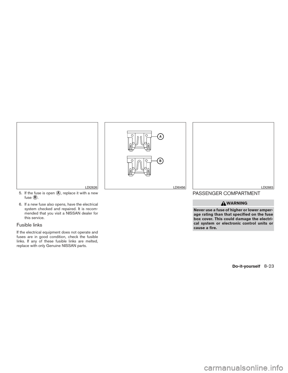
Two types of fuses are used. Type
�Aand�Bare
used in the fuse boxes in the engine compart-
ment. Type
�Bis used in the passenger compart-
ment fuse box.
Type
�Bfuses are provided as spare fuses. They
are stored in the passenger compartment fuse
box.
Type
�Afuses can be installed in the engine
compartment and passenger compartment fuse
boxes. If a type
�Afuse is used to replace a type�Bfuse,
the type
�Afuse will not be level with the fuse
pocket as shown in the illustration. This will not
affect the performance of the fuse. Make sure the
fuse is installed in the fuse box securely.
Type
�Bfuses cannot be used to replace type�A
fuses.
LDI0455LDI0457
FUSES
Do-it-yourself8-21
Page 493 of 671
ENGINE COMPARTMENT
WARNING
Never use a fuse of higher or lower amper-
age rating than that specified on the fuse
box cover. This could damage the electri-
cal system or electronic control units or
cause a fire.
If any electrical equipment does not come on,
check for an open fuse. 1. Be sure the ignition switch and the headlight switch are OFF. 2. Open the engine hood.
3. Remove the fuse box cover by pushing the
tab and lifting the cover up.
4. Remove the fuse with the fuse puller. The fuse puller is located in the center of the fuse
block in the passenger compartment.
VK56VD engine
LDI2962
VK56VD engine
LDI2974
Cummins 5.0L engine
LDI2882
8-22Do-it-yourself
Page 494 of 671
5. If the fuse is open�A, replace it with a new
fuse
�B.
6. If a new fuse also opens, have the electrical system checked and repaired. It is recom-
mended that you visit a NISSAN dealer for
this service.
Fusible links
If the electrical equipment does not operate and
fuses are in good condition, check the fusible
links. If any of these fusible links are melted,
replace with only Genuine NISSAN parts.
PASSENGER COMPARTMENT
WARNING
Never use a fuse of higher or lower amper-
age rating than that specified on the fuse
box cover. This could damage the electri-
cal system or electronic control units or
cause a fire.
LDI2826LDI0456LDI2883
Do-it-yourself8-23
Page 495 of 671
If any electrical equipment does not operate,
check for an open fuse.1. Be sure the ignition switch and the headlight switch are OFF.
2. Open the glove box.
3. Remove the fuse box cover.
4. Locate the fuse that needs to be replaced.
5. Remove the fuse with the fuse puller
�A. 6. If the fuse is open�B, replace it with an
equivalent good fuse
�C.
7. Push the fuse box cover to install.
If a new fuse also opens, have the electrical
system checked and repaired. It is recommended
that you visit a NISSAN dealer for this service.
LDI2884LDI2760
8-24Do-it-yourself
Page 585 of 671
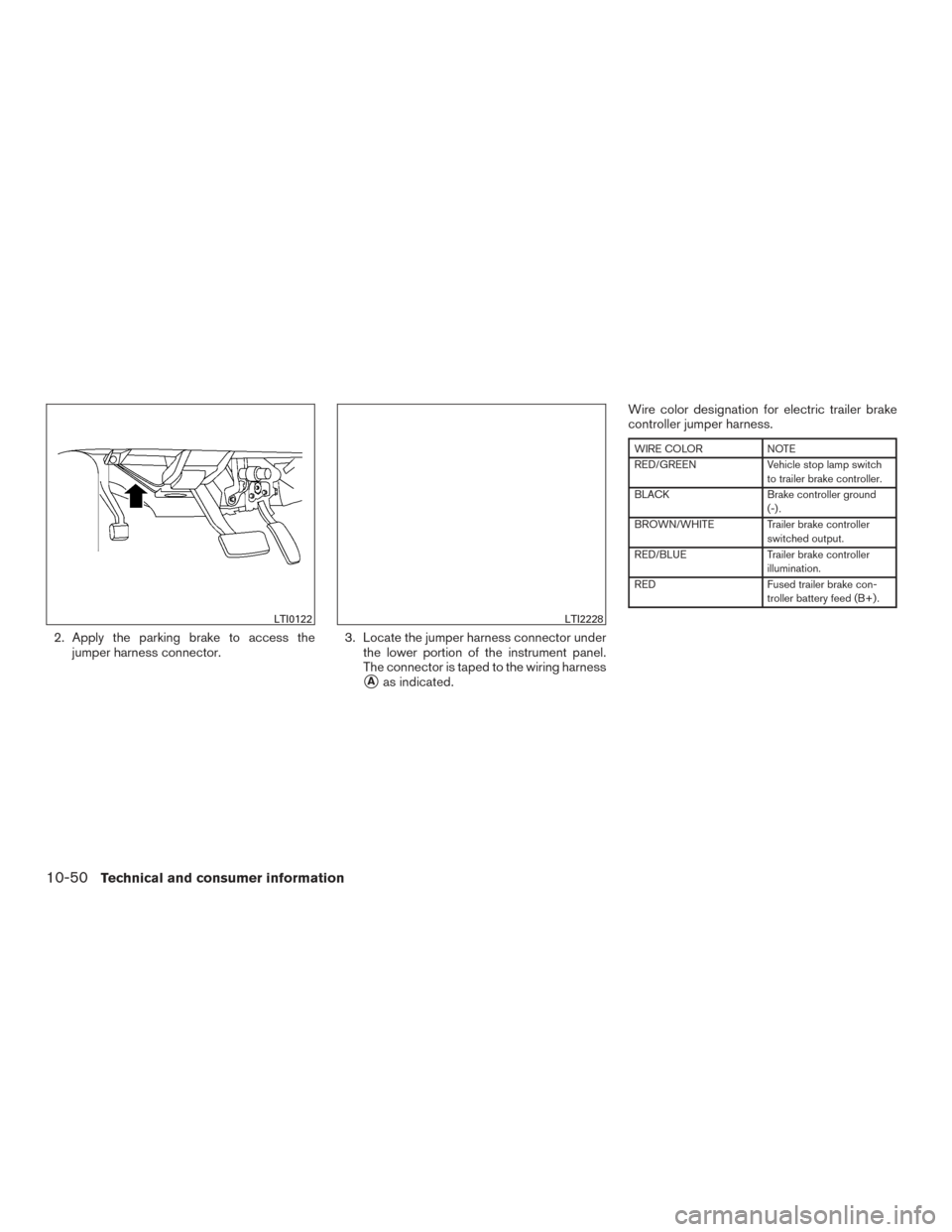
2. Apply the parking brake to access thejumper harness connector. 3. Locate the jumper harness connector under
the lower portion of the instrument panel.
The connector is taped to the wiring harness
�Aas indicated. Wire color designation for electric trailer brake
controller jumper harness.
WIRE COLOR
NOTE
RED/GREEN Vehicle stop lamp switch
to trailer brake controller.
BLACK Brake controller ground
(-) .
BROWN/WHITE Trailer brake controller switched output.
RED/BLUE Trailer brake controller
illumination.
RED Fused trailer brake con-
troller battery feed (B+) .
LTI0122LTI2228
10-50Technical and consumer information
Page 600 of 671

Engine oil and oil filter recommendation . .10-7
Engine oil pressure gauge......2-11,2-12
Engine oil pressure warning light ......2-25
Engine oil viscosity ..............10-7
Engine serial number ............10-16
Engine specifications ............10-8
Engine coolant temperature gauge .......2-9
Engineoilpressuregauge........2-11,2-12
Enterbutton....................4-4
Event Data recorders .............10-61
Exhaust gas (Carbon monoxide) .........5-2
Explanation of maintenance items ........9-2
Explanation of scheduled maintenance items . .9-5
Extendedstorageswitch ............2-73
F
Flashers
(See hazard warning flasher switch) .......6-2
Flat tire .......................6-3
Floor mat positioning aid .............7-5
Fluid Brake fluid ..................8-13
Capacities and recommended
fuel/lubricants ................10-2
Engine coolant .................8-5
Engine oil ...................8-7
Power steering fluid .............8-12
Windshield-washerfluid...........8-13
F.M.V.S.S. certification label ..........10-16
Foglightswitch .................2-57
Four-Wheel Drive ................5-44
Front air bag system
(See supplemental restraint system) . .1-58, 1-72
Front and rear sonar system ..........5-60Front power seat adjustment
...........1-5
Frontseats.....................1-2
Fuel Capacities and recommended
fuel/lubricants ................10-2
Fuel economy ................5-44
Fuel gauge ..................2-10
Fuel octane rating ..............10-6
Fuel recommendation ............10-4
Loose fuel cap warning ...........2-45
Fuel Cell Vehicle (FCV) System Tirepressure.................8-32
Fuel efficient driving tips .............5-42
Fuel-filler door ..................3-23
Fuelgauge....................2-10
Fuses.......................8-21
Fusiblelinks ...................8-23
G
Garage door opener, HomeLink® Universal Trans-
ceiver .....2-89,2-90,2-91,2-92,2-92,2-93
Gauge Automatic transmission fluid temperature
gauge.....................2-11
Engine coolant temperature gauge .....2-9
Engine oil pressure gauge ......2-11,2-12
Fuel gauge ..................2-10
Odometer ...................2-8
Speedometer .................2-8
Tachometer ..................2-9
Trip computer ................2-13
Trip odometer .................2-8
Voltmeter...................2-12
General maintenance ...............9-2 Glovebox.....................2-77
Groceryhooks..................2-82
H
Hands-free phone system, Bluetooth® . . .4-114, 4-126
Hazard warning flasher switch ..........6-2
Headlightaimingcontrol ............2-55
Headlightandturnsignalswitch........2-53
Headlightcontrolswitch ............2-53
Headlights....................8-27
Headlights, aiming control ............2-55
Head restraints ..................1-10
Heated
rear seats ................2-61
Heated seats ...................2-60
Heated seat switches ..............4-85
Heated steering wheel switch .........2-62
Heater Heater and air conditioner (automatic)
(if so equipped) ...............4-42
Heater and air conditioner controls .....4-43
Heater operation ...........4-35,4-44
Heater and air conditioner (automatic) .....4-42
Hill descent control switch ...........2-64
Hill descent control system ...........5-59
Hill start assist system ..............5-60
HomeLink® Universal Transceiver . . .2-89, 2-90, 2-91, 2-92, 2-92, 2-93
Hood.......................3-22
Horn .......................2-58
11-3
Page 635 of 671

WARNING
Always follow the instructions below. Fail-
ure to do so could result in damage to the
charging system and cause personal
injury.1. If the booster battery is in another vehicle, position the two vehicles to bring their bat-
teries near each other.
Do not allow the two vehicles to touch.
2. Apply the parking brake. Move the shift lever to P (Park) . Switch off all unnecessary elec-
trical systems (lights, heater, air conditioner,
etc.) . 3. Ensure the vent caps are level and tight.
4. Remove the fuse/fusible link box and con-
nect jumper cables in the sequence illus-
trated (
�A,�B,�C,�D).
CAUTION
●Always connect positive (�) to positive
(�) and negative (�) to body ground (for
example, strut mounting bolt, engine
lift bracket, etc.) — not to the battery.
● Make sure the jumper cables do not
touch moving parts in the engine com-
partment and that the cable clamps do
not contact any other metal. 5. Start the engine of the booster vehicle and
let it run for a few minutes.
6. Keep the engine speed of the booster ve- hicle at about 2,000 rpm, and start the en-
gine of the vehicle being jump started.
CAUTION
Do not keep the starter motor engaged for
more than 10 seconds. If the engine does
not start right away, turn the key off and
wait 3 to 4 seconds before trying again.
7. After starting the engine, carefully discon- nect the negative cable and then the positive
cable.
LCE2223
In Case of Emergency5-3

1. Windshield-washer fluid reservoir
2. Fuse box
3. Engine oil dipstick
4. Power steering fluid reservoir
5. Engine oil filler cap
6. Brake fluid reservoir
7. Air cleaner
8. F")