2017 NISSAN TITAN brake sensor
[x] Cancel search: brake sensorPage 16 of 671
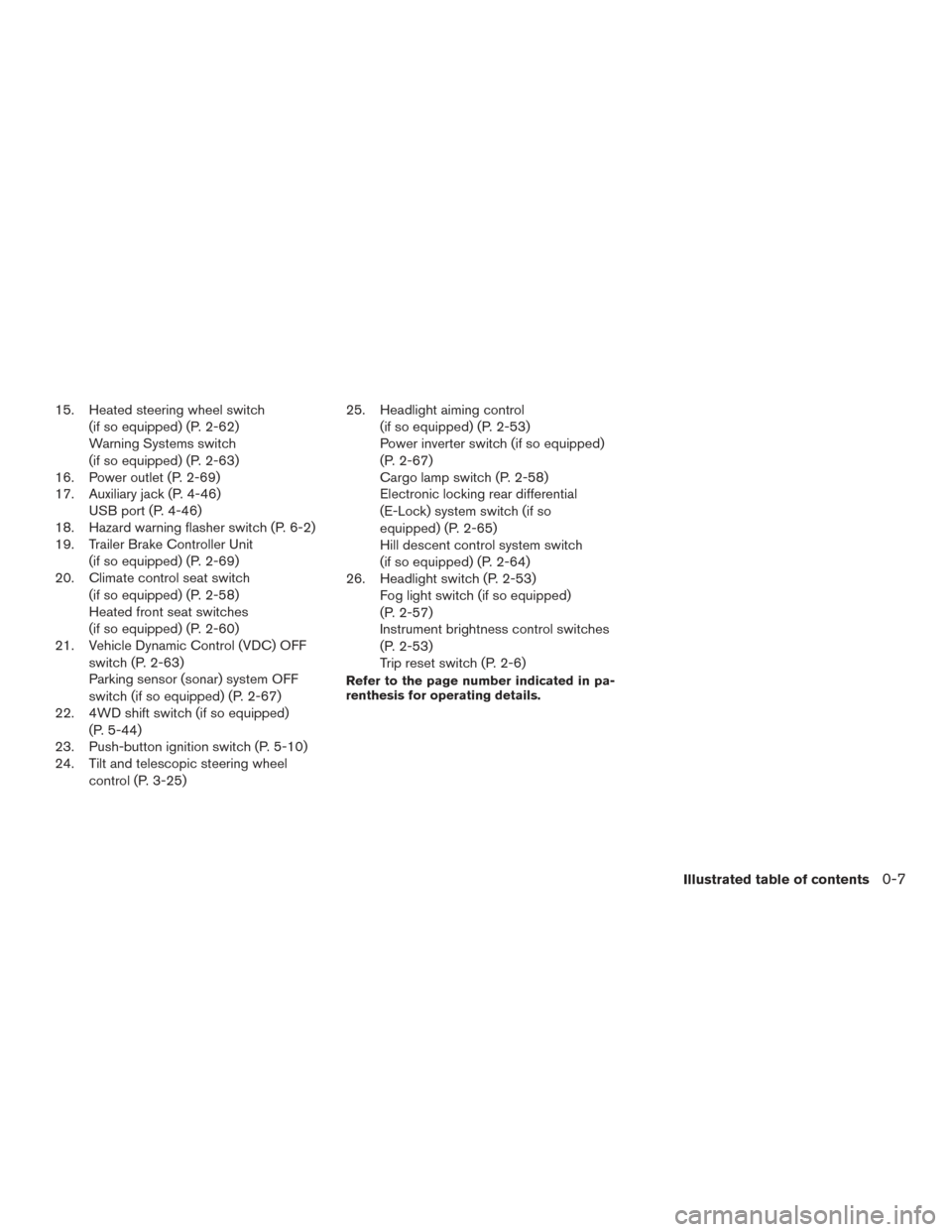
15. Heated steering wheel switch(if so equipped) (P. 2-62)
Warning Systems switch
(if so equipped) (P. 2-63)
16. Power outlet (P. 2-69)
17. Auxiliary jack (P. 4-46) USB port (P. 4-46)
18. Hazard warning flasher switch (P. 6-2)
19. Trailer Brake Controller Unit
(if so equipped) (P. 2-69)
20. Climate control seat switch
(if so equipped) (P. 2-58)
Heated front seat switches
(if so equipped) (P. 2-60)
21. Vehicle Dynamic Control (VDC) OFF
switch (P. 2-63)
Parking sensor (sonar) system OFF
switch (if so equipped) (P. 2-67)
22. 4WD shift switch (if so equipped)
(P. 5-44)
23. Push-button ignition switch (P. 5-10)
24. Tilt and telescopic steering wheel
control (P. 3-25) 25. Headlight aiming control
(if so equipped) (P. 2-53)
Power inverter switch (if so equipped)
(P. 2-67)
Cargo lamp switch (P. 2-58)
Electronic locking rear differential
(E-Lock) system switch (if so
equipped) (P. 2-65)
Hill descent control system switch
(if so equipped) (P. 2-64)
26. Headlight switch (P. 2-53) Fog light switch (if so equipped)
(P. 2-57)
Instrument brightness control switches
(P. 2-53)
Trip reset switch (P. 2-6)
Refer to the page number indicated in pa-
renthesis for operating details.
Illustrated table of contents0-7
Page 105 of 671
Heated rear seat switches (if so equipped)..........2-61
Heated steering wheel switch (if so equipped) .......2-62
Warning systems switch (if so equipped) ............2-63
Vehicle Dynamic Control (VDC) off switch . . .........2-63
Hill descent control switch (if so equipped) ..........2-64
Electronic locking rear differential (E-Lock) system
switch (if so equipped) ............................ 2-65
Power inverter switch (if so equipped) ..............2-67
Parking Sensor (sonar) System OFF Switch
(if so equipped) .................................. 2-67
Tow mode switch (if so equipped) . . ................2-68
E-call (SOS) switch (if so equipped) ................2-69
Trailer Brake Controller Unit (TBCU)
(if so equipped) .................................. 2-69
Power outlets .................................... 2-69
12v Outlets . . ................................. 2-69
120v outlets (if so equipped) ...................2-72
Extended storage switch .......................... 2-73
Storage ......................................... 2-74
Front-door pockets ............................ 2-74
Console side pockets .......................... 2-75
Seatback pockets (if so equipped) ..............2-75
Under-seat storage (if so equipped) .............2-76
Console box storage trays (if so equipped) .......2-77 Glove box
.................................... 2-77
Console box (if so equipped) ...................2-77
Center armrest storage (if so equipped) ..........2-78
Under front seat storage bin (if so equipped) .....2-79
Sunglasses holder (if so equipped) ..............2-79
Cup holders .................................. 2-80
Grocery hooks (if so equipped) .................2-82
Bed liner storage bins (if so equipped) ...........2-82
Windows ........................................ 2-83
Power windows ............................... 2-83
Rear power window switch (if so equipped) ......2-85
Rear sliding window (if so equipped) ............2-86
Interior
lights ..................................... 2-87
Console light (if so equipped) ...................2-88
Map lights (if so equipped) .....................2-88
Personal Lights (if so equipped) .................2-89
Homelink® Universal Transceiver (if so equipped) ....2-89
Programming HomeLink® ......................2-90
Programming HomeLink® for Canadian
customers and gate openers ....................2-91
Operating the HomeLink® Universal
Transceiver ................................... 2-92
Programming trouble-diagnosis .................2-92
Page 108 of 671
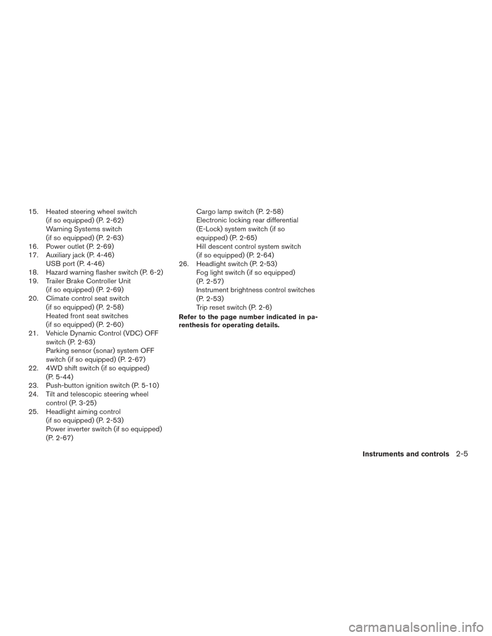
15. Heated steering wheel switch(if so equipped) (P. 2-62)
Warning Systems switch
(if so equipped) (P. 2-63)
16. Power outlet (P. 2-69)
17. Auxiliary jack (P. 4-46) USB port (P. 4-46)
18. Hazard warning flasher switch (P. 6-2)
19. Trailer Brake Controller Unit
(if so equipped) (P. 2-69)
20. Climate control seat switch
(if so equipped) (P. 2-58)
Heated front seat switches
(if so equipped) (P. 2-60)
21. Vehicle Dynamic Control (VDC) OFF
switch (P. 2-63)
Parking sensor (sonar) system OFF
switch (if so equipped) (P. 2-67)
22. 4WD shift switch (if so equipped)
(P. 5-44)
23. Push-button ignition switch (P. 5-10)
24. Tilt and telescopic steering wheel
control (P. 3-25)
25. Headlight aiming control
(if so equipped) (P. 2-53)
Power inverter switch (if so equipped)
(P. 2-67) Cargo lamp switch (P. 2-58)
Electronic locking rear differential
(E-Lock) system switch (if so
equipped) (P. 2-65)
Hill descent control system switch
(if so equipped) (P. 2-64)
26. Headlight switch (P. 2-53) Fog light switch (if so equipped)
(P. 2-57)
Instrument brightness control switches
(P. 2-53)
Trip reset switch (P. 2-6)
Refer to the page number indicated in pa-
renthesis for operating details.
Instruments and controls2-5
Page 144 of 671
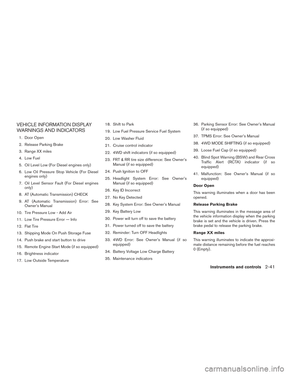
VEHICLE INFORMATION DISPLAY
WARNINGS AND INDICATORS
1. Door Open
2. Release Parking Brake
3. Range XX miles
4. Low Fuel
5. Oil Level Low (For Diesel engines only)
6. Low Oil Pressure Stop Vehicle (For Dieselengines only)
7. Oil Level Sensor Fault (For Diesel engines only)
8. AT (Automatic Transmission) CHECK
9. AT (Automatic Transmission) Error: See Owner’s Manual
10. Tire Pressure Low - Add Air
11. Low Tire Pressure Error — Info
12. Flat Tire
13. Shipping Mode On Push Storage Fuse
14. Push brake and start button to drive
15. Remote Engine Start Mode (if so equipped)
16. Brightness indicator
17. Low Outside Temperature 18. Shift to Park
19. Low Fuel Pressure Service Fuel System
20. Low Washer Fluid
21. Cruise control indicator
22. 4WD shift indicators (if so equipped)
23. FRT & RR tire size difference: See Owner’s
Manual (if so equipped)
24. Push Ignition to OFF
25. Headlight System Error: See Owner’s Manual (if so equipped)
26. Key ID Incorrect
27. No Key Detected
28. Key System Error: See Owner’s Manual
29. Key Battery Low
30. Power will turn off to save the battery
31. Power turned off to save the battery
32. Reminder: Turn OFF Headlights
33. 4WD Error: See Owner’s Manual (if so equipped)
34. Battery Voltage Low Charge Battery
35. Maintenance indicators 36. Parking Sensor Error: See Owner’s Manual
(if so equipped)
37. TPMS Error: See Owner’s Manual
38. 4WD MODE SHIFTING (if so equipped)
39. Loose Fuel Cap (if so equipped)
40. Blind Spot Warning (BSW) and Rear Cross Traffic Alert (RCTA) indicator (if so
equipped)
41. Malfunction: See Owner’s Manual (if so equipped)
Door Open
This warning illuminates when a door has been
opened.
Release Parking Brake
This warning illuminates in the message area of
the vehicle information display when the parking
brake is set and the vehicle is driven. Press the
brake pedal to release the parking brake.
Range XX miles
This warning illuminates to indicate the approxi-
mate distance remaining before the fuel reaches
0 (Empty) .
Instruments and controls2-41
Page 383 of 671
When adding air to an under-inflated tire, the TPMS
with Easy Fill Tire Alert provides visual and audible
signals outside the vehicle to help you inflate the
tires to the recommended COLD tire pressure.
Vehicle set-up1. Park the vehicle in a safe and level place.
2. Apply the parking brake and place the shift lever to the P (Park) position.
3. Place the ignition switch to the ON position. Do not start the engine.
Operation 1. Add air to the tire.
2. After a few seconds, the hazard indicators will start flashing.
3. When the designated pressure is reached, the horn beeps once and the hazard indica-
tors stop flashing.
4. Perform the above steps for each tire. ●If the tire is over-inflated more than ap-
proximately 4 psi (30 kPa) , the horn
beeps and the hazard indicators flash
three times. To correct the pressure, push
the core of the valve stem on the tire
briefly to release pressure. When the
pressure reaches the designated pres-
sure, the horn beeps once. ●
If the hazard indicator does not flash
within approximately 15 seconds after
starting to inflate the tire, it indicates that
the Easy Fill Tire Alert is not operating.
● The TPMS will not activate the Easy Fill
Tire Alert under the following conditions:
– If there is interference from an external device or transmitter.
– The air pressure from the inflation device is not sufficient to inflate the tire.
– There is a malfunction in the TPMS sys- tem.
– There is a malfunction in the horn or haz- ard indicators.
– The identification code of the tires pres- sure sensor is not registered to the sys-
tem.
– The battery of the tire pressure sensor is low.
● If the Easy Fill Tire Alert does not operate
due to TPMS interference, move the ve-
hicle about 3 ft (1 m) backward or forward
and try again.
If the Easy Fill Tire Alert is not working, use a tire
pressure gauge.
ON-PAVEMENT AND OFF-ROAD
DRIVING PRECAUTIONS
Utility vehicles have a significantly higher
rollover rate than other types of vehicles.
They have higher ground clearance than passen-
ger cars to make them capable of performing in a
variety of on-pavement and off-road applications.
This gives them a higher center of gravity than
ordinary vehicles. An advantage of higher ground
clearance is a better view of the road, allowing
you to anticipate problems. However, they are not
designed for cornering at the same speeds as
conventional 2-wheel drive vehicles any more
than low-slung sports cars are designed to per-
form satisfactorily under off-road conditions. If at
all possible, avoid sharp turns at high speeds. As
with other vehicles of this type, failure to operate
this vehicle correctly may result in loss of control
or vehicle rollover. In a rollover crash, an unbelted
person is significantly more likely to die than a
person wearing a seat belt.
For additional information, refer to “Driving safety
precautions” in this section.
5-6Starting and driving
Page 432 of 671
ANTI-LOCK BRAKING SYSTEM
(ABS)
WARNING
●The ABS is a sophisticated device, but it
cannot prevent accidents resulting from
careless or dangerous driving tech-
niques. It can help maintain vehicle con-
trol during braking on slippery surfaces.
Remember that stopping distances on
slippery surfaces will be longer than on
normal surfaces even with ABS. Stop-
ping distances may also be longer on
rough, gravel or snow covered roads, or
if you are using tire chains. Always
maintain a safe distance from the ve-
hicle in front of you. Ultimately, the
driver is responsible for safety.
● Tire type and condition may also affect
braking effectiveness.
– When replacing tires, install the specified size of tires on all four
wheels. – When installing a spare tire, make
sure that it is the proper size and type
as specified on the Tire and Loading
Information label. For additional in-
formation, refer to “Tire and loading
information label” in the “Technical
and consumer information” section
of this manual.
– For additional information, refer to “Wheels and tires” in the “Do-it-
yourself” section of this manual.
The ABS controls the brakes so the wheels do
not lock during hard braking or when braking on
slippery surfaces. The system detects the rota-
tion speed at each wheel and varies the brake
fluid pressure to prevent each wheel from locking
and sliding. By preventing each wheel from lock-
ing, the system helps the driver maintain steering
control and helps to minimize swerving and spin-
ning on slippery surfaces.
Using the system
Depress the brake pedal and hold it down. De-
press the brake pedal with firm steady pressure,
but do not pump the brakes. The ABS will oper-
ate to prevent the wheels from locking up. Steer
the vehicle to avoid obstacles.
WARNING
Do not pump the brake pedal. Doing so
may result in increased stopping
distances.
Self-test feature
The ABS includes electronic sensors, electric
pumps, hydraulic solenoids and a computer. The
computer has a built-in diagnostic feature that
tests the system each time you start the engine
and move the vehicle at a low speed in forward or
reverse. When the self-test occurs, you may hear
a “clunk” noise and/or feel a pulsation in the brake
pedal. This is normal and does not indicate a
malfunction. If the computer senses a malfunc-
tion, it switches the ABS off and illuminates the
ABS warning light on the instrument panel. The
brake system then operates normally, but without
anti-lock assistance.
If the ABS warning light illuminates during the
self-test or while driving, have the vehicle
checked. It is recommended that you visit a
NISSAN dealer for this service.
Normal operation
The ABS operates at speeds above3-6mph(5
- 10 km/h). The speed varies according to road
conditions.
Starting and driving5-55
Page 433 of 671
When the ABS senses that one or more wheels
are close to locking up, the actuator rapidly ap-
plies and releases hydraulic pressure. This action
is similar to pumping the brakes very quickly. You
may feel a pulsation in the brake pedal and hear a
noise from under the hood or feel a vibration from
the actuator when it is operating. This is normal
and indicates that the ABS is operating properly.
However, the pulsation may indicate that road
conditions are hazardous and extra care is re-
quired while driving.
BRAKE ASSIST
When the force applied to the brake pedal ex-
ceeds a certain level, the brake assist is activated
generating greater braking force than a conven-
tional brake booster even with light pedal force.
WARNING
The brake assist is only an aid to assist
braking operation and is not a collision
warning or avoidance device. it is the driv-
ers responsibility to stay alert, drive safely
and be in control of the vehicle at all times.The Vehicle Dynamic Control (VDC) system uses
various sensors to monitor driver inputs and ve-
hicle motion. Under certain driving conditions,
the VDC System helps to perform the following
functions:
● Controls brake pressure to reduce wheel
slip on one slipping drive wheel so power is
transferred to a non slipping drive wheel on
the same axle.
● Controls brake pressure and engine output
to reduce drive wheel slip based on vehicle
speed (traction control function) .
● If the 4WD transfer case is shifted into 4LO
the
indicator light will come on and
the VDC system will be turned off. For addi-
tional information, refer to “Using 4-wheel
drive (4WD)” in this section.
● Controls brake pressure at individual wheels
and engine output to help the driver maintain
control of the vehicle in the following condi-
tions:
– understeer (vehicle tends to not follow the steered path despite increased steer-
ing input)
– oversteer (vehicle tends to spin due to certain road or driving conditions) The VDC system can help the driver to maintain
control of the vehicle, but it cannot prevent loss of
vehicle control in all driving situations.
When the VDC system operates, the
indi-
cator in the instrument panel flashes so note the
following:
● The road may be slippery or the system may
determine some action is required to help
keep the vehicle on the steered path.
● You may feel a pulsation in the brake pedal
and hear a noise or vibration from under the
hood. This is normal and indicates that the
VDC system is working properly.
● Adjust your speed and driving to the road
conditions.
For additional information, refer to “Slip indicator
light” and ”Vehicle Dynamic Control (VDC) OFF
indicator light” in the ”Instruments and controls”
section of this manual.
If a malfunction occurs in the system, the
indicator light will come on in the instrument
panel. The VDC system automatically turns off
when these indicator lights are off.
The VDC OFF switch is used to turn off the VDC
system. The
indicator illuminates to indi-
cate the VDC system is off.
VEHICLE DYNAMIC CONTROL (VDC)
SYSTEM
5-56Starting and driving
Page 437 of 671
WARNING
●Never rely solely on the hill start assist
system to prevent the vehicle from mov-
ing backward on a hill. Always drive
carefully and attentively. Depress the
brake pedal when the vehicle is stopped
on a steep hill. Be especially careful
when stopped on a hill on frozen or
muddy roads. Failure to prevent the ve-
hicle from rolling backwards may result
in a loss of control of the vehicle and
possible serious injury or death.
● The hill start assist system is not de-
signed to hold the vehicle at a standstill
on a hill. Depress the brake pedal when
the vehicle is stopped on a steep hill.
Failure to do so may cause the vehicle
to roll backwards and may result in a
collision or serious personal injury.
● The hill start assist may not prevent the
vehicle from rolling backwards on a hill
under all load or road conditions. Al-
ways be prepared to depress the brake
pedal to prevent the vehicle from rolling
backwards. Failure to do so may result
in a collision or serious personal injury. When the vehicle is stopped on a hill, the hill start
assist system automatically keeps the brakes ap-
plied. This helps prevents the vehicle from rolling
backward in the time it takes the driver to release
the brake pedal and apply the accelerator when
the vehicle is stopped on a hill.
Hill start assist will operate automatically under
the following conditions:
● The shift lever is shifted to a forward or
reverse gear.
● The vehicle is stopped completely on a hill
by applying the brake.
The maximum holding time is 2 seconds. After
2 seconds the vehicle will begin to roll back and
hill start assist will stop operating completely.
Hill start assist will not operate when the shift
lever is shifted into N (Neutral) or P (Park) or on a
flat and level road. When the VDC warning light
illuminates in the meter, the hill start assist system
will not operate. The sonar (parking sensor) system sounds a tone
to inform the driver of obstacles near the bumper.
When the “DISPLAY” key is ON, the sonar view
will automatically appear in the meter.
WARNING
●
The sonar (parking sensor) system is a
convenience but it is not a substitute for
proper parking.
● The driver is always responsible for
safety during parking and other maneu-
vers. Always look around and check that
it is safe to do so before parking.
LSD2465
HILL START ASSIST SYSTEM FRONT AND REAR SONAR SYSTEM
(if so equipped)
5-60Starting and driving