2017 NISSAN ROGUE SPORT wheel
[x] Cancel search: wheelPage 128 of 512

The heater is controlled by a thermo-
stat, automatically turning the heater
on and off. The indicator light will
remain on as long as the switch is on.
When the vehicle’s interior is warmed,
or before you leave the vehicle, be
sure to turn off the switch.
JVI1593X
The Intelligent Lane Intervention (I-LI)
switch is used to turn on and off the I-LI
system.
The I-LI system must be turned on with
the I-LI switch every time the ignition is
placed in the ON position.
When the I-LI switch is turned off, the
indicator
on the switch is off.
The I-LI system warns the driver with a
warning indicator and a chime, and helps
assist the driver to return the vehicle to
the center of the traveling lane by apply-
ing the brakes to the left or right wheels
individually (for a short period of time). For
additional information, see “Intelligent
Lane Intervention (I-LI)” (P.5-37).
JVI1594X
The Blind Spot Warning (BSW) switch is
used to temporarily turn on and off the
BSW system that is activated using the
settings menu of the vehicle information
display.
When the BSW switch is turned off, the
indicator
on the switch is off. The
indicator will also be off if the BSW system
is deactivated using the vehicle informa-
tion display.
The BSW system helps alert the driver of
other vehicles in adjacent lanes when
changing lanes. For additional informa-
tion, see “Blind Spot Warning (BSW)” (P.5-
42).
Instruments and controls2-51
INTELLIGENT LANE INTERVENTION
(I-LI) SWITCH (if so equipped) BLIND SPOT WARNING (BSW)
SWITCH (if so equipped)
Page 129 of 512

2-52Instruments and controls
SIC4544
The vehicle should be driven with the
Vehicle Dynamic Control (VDC) system on
for most driving conditions.
If the vehicle is stuck in mud or snow, the
VDC system reduces the engine output to
reduce wheel spin. The engine speed will
be reduced even if the accelerator is
depressed to the floor. If maximum en-
gine power is needed to free a stuck
vehicle, turn the VDC system off.
To turn off the VDC system, push the VDC
OFF switch. The
indicator light will
illuminate.
Push the VDC OFF switch again or restart the
engine to turn on the system. (See “Vehicle
Dynamic Control (VDC) system” (P.5-108).)
JVI1595X
The Intelligent 4x4 LOCK switch is located
on the instrument panel. The AWD LOCK
indicator light will illuminate when the
switch is turned on. For additional infor-
mation, refer to “Intelligent 4x4” (P.5-100).
Each time you push the switch, the AWD
mode will switch: AUTO ?LOCK ?AUTO.
JVS0185X
The ECO mode system helps to enhance
the fuel economy by controlling the
engine and CVT operation (for CVT mod-
els) automatically to avoid rapid accelera-
tion.
To turn on the ECO mode system, push
the ECO switch. The ECO mode indicator
appears on the meter.
To turn off the ECO mode, push the ECO
switch again. The ECO mode indicator will
turn off.
. The ECO mode system cannot be
turned off while the accelerator pedal
is depressed even if the ECO switch is
pushed to OFF. Release the accelera-
tor pedal to turn off the ECO mode
VEHICLE DYNAMIC CONTROL (VDC)
OFF SWITCH INTELLIGENT 4X4 LOCK SWITCH (if
so equipped)
ECO MODE SWITCH
Page 174 of 512

JVP0503X
LOOSE FUEL CAP warning message
The LOOSE FUEL CAP warning messageis displayed on the vehicle information
display when the fuel-filler cap is not
tightened correctly after the vehicle has
been refueled. It may take a few driving
trips for the message to be displayed. To
turn off the warning message, do the
following procedure:
1. Remove and install the fuel-filler capas soon as possible. For additional
information, refer to “Fuel-filler cap”
(P.3-27).
2. Tighten the fuel-filler cap until it clicks. 3. Push the OK button
on the steering
wheel for about 1 second to turn off
the LOOSE FUEL CAP warning mes-
sage after tightening the fuel cap.
WARNING
Do not adjust the steering wheel
while driving. You could lose control
of your vehicle and cause an acci-
dent.
Pre-driving checks and adjustments3-29
TILT/TELESCOPIC STEERING
Page 175 of 512

3-30Pre-driving checks and adjustments
JVP0301X
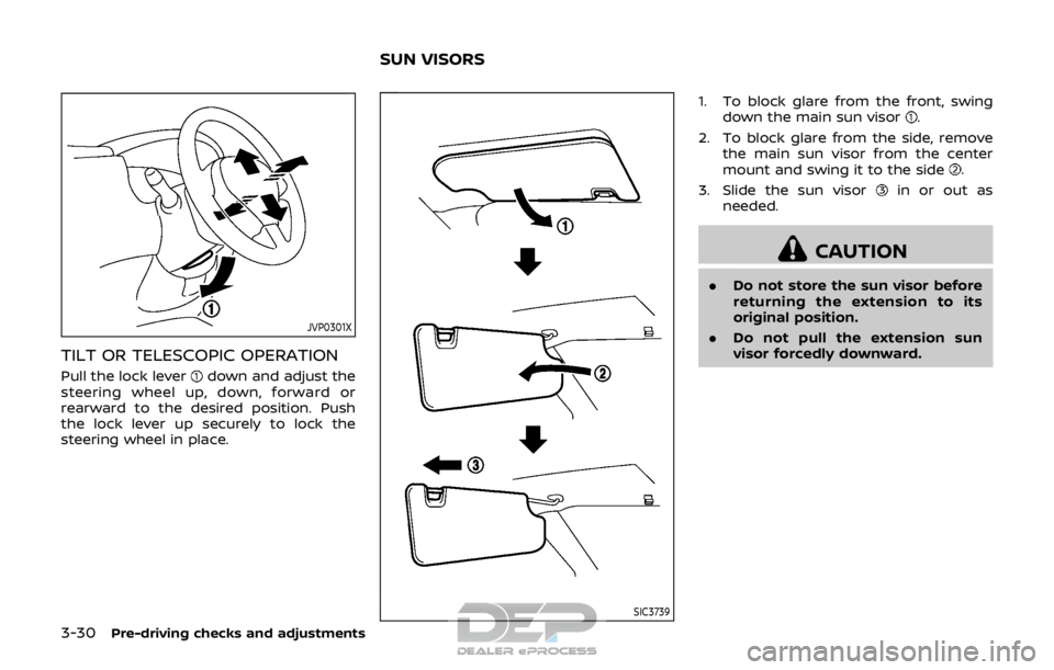
TILT OR TELESCOPIC OPERATION
Pull the lock leverdown and adjust the
steering wheel up, down, forward or
rearward to the desired position. Push
the lock lever up securely to lock the
steering wheel in place.
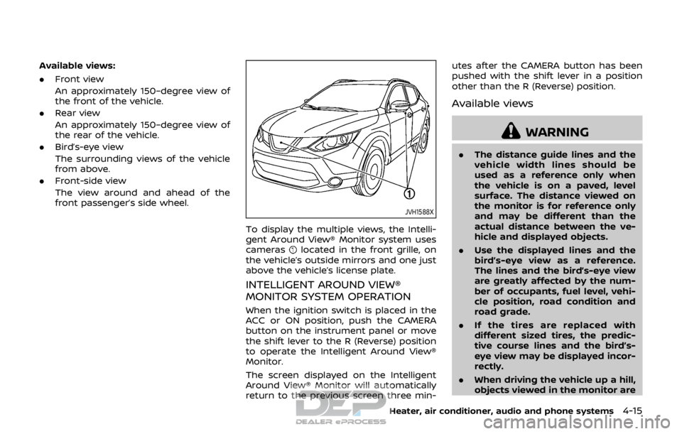
SIC3739
1. To block glare from the front, swing down the main sun visor.
2. To block glare from the side, remove the main sun visor from the center
mount and swing it to the side
.
3. Slide the sun visor
in or out as
needed.
CAUTION
. Do not store the sun visor before
returning the extension to its
original position.
. Do not pull the extension sun
visor forcedly downward.
SUN VISORS
Page 181 of 512

FM-AM-SAT radio with Compact Disc (CD)
player (Type B) (if so equipped) ............................... 4-63
USB (Universal Serial Bus)
connection port ................................................................... 4-74
AUX (Auxiliary) input jack .............................................. 4-75
Steering wheel switch for audio control ......... 4-75
Antenna ........................................................................\
.............. 4-77
CD/USB memory care and cleaning ................... 4-77
NissanConnect
SMMobile Apps smartphone
integration (if so equipped) ............................................... 4-78
Registering with NissanConnect
SM
Mobile Apps ........................................................................\
..... 4-78
Connect phone ..................................................................... 4-78
Application download ..................................................... 4-78
NissanConnect
SMServices (if so equipped) .......... 4-79
Siri® Eyes Free ........................................................................\
...... 4-79 General Information .......................................................... 4-79
Requirements ........................................................................\
. 4-79
Siri® Eyes Free Activation ............................................. 4-80
Operating Siri® Eyes Free ............................................. 4-80
Changing Siri® Eyes Free Settings
(models with navigation system) ........................... 4-80
Changing Siri® Eyes Free Settings
(models without navigation system) .................. 4-81
Troubleshooting guide ................................................... 4-82
Car phone or CB radio .......................................................... 4-83 Bluetooth® Hands-Free Phone System
(models without navigation system) ........................ 4-83
Regulatory information ............................................... 4-84
Using the system .............................................................. 4-85
Bluetooth® Hands-Free Phone System
(models with navigation system) ................................. 4-93 Regulatory information ............................................... 4-94
Control buttons and microphone ....................... 4-95
Voice command ................................................................ 4-95
Connecting procedure ................................................. 4-96
Vehicle phonebook ......................................................... 4-96
Making a call ........................................................................\
4-97
Receiving a call ................................................................... 4-97
During a call ........................................................................\
.. 4-97
Ending a call ........................................................................\
. 4-97
Text messaging (if so equipped) .......................... 4-97
Phone and Bluetooth® settings ............................ 4-99
NISSAN Voice Recognition system
(models with navigation system) ............................. 4-100 Using the system .......................................................... 4-101
System features ............................................................ 4-102
Phone voice commands ......................................... 4-103
Navigation system voice commands ........... 4-103
Audio system voice commands ....................... 4-104
Information voice commands ............................ 4-104
My APPS voice commands ................................... 4-104
Help voice commands .............................................. 4-104
Troubleshooting guide ............................................ 4-104
Page 194 of 512

Available views:
.Front view
An approximately 150–degree view of
the front of the vehicle.
. Rear view
An approximately 150–degree view of
the rear of the vehicle.
. Bird’s-eye view
The surrounding views of the vehicle
from above.
. Front-side view
The view around and ahead of the
front passenger’s side wheel.
JVH1588X
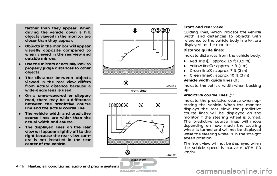
To display the multiple views, the Intelli-
gent Around View® Monitor system uses
cameras
located in the front grille, on
the vehicle’s outside mirrors and one just
above the vehicle’s license plate.
INTELLIGENT AROUND VIEW®
MONITOR SYSTEM OPERATION
When the ignition switch is placed in the
ACC or ON position, push the CAMERA
button on the instrument panel or move
the shift lever to the R (Reverse) position
to operate the Intelligent Around View®
Monitor.
The screen displayed on the Intelligent
Around View® Monitor will automatically
return to the previous screen three min- utes after the CAMERA button has been
pushed with the shift lever in a position
other than the R (Reverse) position.
Available views
WARNING
.
The distance guide lines and the
vehicle width lines should be
used as a reference only when
the vehicle is on a paved, level
surface. The distance viewed on
the monitor is for reference only
and may be different than the
actual distance between the ve-
hicle and displayed objects.
. Use the displayed lines and the
bird’s-eye view as a reference.
The lines and the bird’s-eye view
are greatly affected by the num-
ber of occupants, fuel level, vehi-
cle position, road condition and
road grade.
. If the tires are replaced with
different sized tires, the predic-
tive course lines and the bird’s-
eye view may be displayed incor-
rectly.
. When driving the vehicle up a hill,
objects viewed in the monitor are
Heater, air conditioner, audio and phone systems4-15
Page 195 of 512

4-16Heater, air conditioner, audio and phone systems
farther than they appear. When
driving the vehicle down a hill,
objects viewed in the monitor are
closer than they appear.
. Objects in the monitor will appear
visually opposite compared to
when viewed in the rearview and
outside mirrors.
. Use the mirrors or actually look to
properly judge distances to other
objects.
. The distance between objects
viewed in the rear view differs
from actual distance because a
wide-angle lens is used.
. On a snow-covered or slippery
road, there may be a difference
between the predictive course
line and the actual course line.
. The vehicle width and predictive
course lines are wider than the
actual width and course.
. The displayed lines on the rear
view will appear slightly off to the
right because the rear view cam-
era is not installed in the rear
center of the vehicle.
SAA1840
Front view
SAA1896Rear view
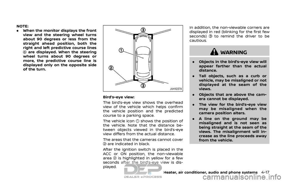
Front and rear view:
Guiding lines, which indicate the vehicle
width and distances to objects with
reference to the vehicle body line
, are
displayed on the monitor.
Distance guide lines:
Indicate distances from the vehicle body.
. Red line
: approx. 1.5 ft (0.5 m)
. Yellow line
: approx. 3 ft (1 m)
. Green line
: approx. 7 ft (2 m)
. Green line
: approx. 10 ft (3 m)
Vehicle width guide lines
:
Indicate the vehicle width when backing
up.
Predictive course lines
:
Indicate the predictive course when op-
erating the vehicle. When the monitor
displays the rear view, the predictive
course lines will be displayed on the
monitor if the steering wheel is turned.
The predictive course lines will move
depending on how much the steering
wheel is turned and will not be displayed
while the steering wheel is in the straight
ahead position.
The front view will not be displayed when
the vehicle speed is above 6 MPH (10
km/h).
Page 196 of 512

NOTE:
.When the monitor displays the front
view and the steering wheel turns
about 90 degrees or less from the
straight ahead position, both the
right and left predictive course lines
are displayed. When the steering
wheel turns about 90 degrees or
more, the predictive course line is
displayed only on the opposite side
of the turn.
JVH1037X
Bird’s-eye view:
The bird’s-eye view shows the overhead
view of the vehicle which helps confirm
the vehicle position and the predicted
course to a parking space.
The vehicle icon
shows the position of
the vehicle. Note that the distance be-
tween objects viewed in the bird’s-eye
view differs from the actual distance.
The areas that the cameras cannot cover
are indicated in black.
After the ignition switch is placed in the
ACC or ON position, the non-viewable
area
is highlighted in yellow for a few
seconds after the bird’s-eye view is dis-
played. In addition, the non-viewable corners are
displayed in red (blinking for the first few
seconds)
to remind the driver to be
cautious.
WARNING
. Objects in the bird’s-eye view will
appear farther than the actual
distance.
. Tall objects, such as a curb or
vehicle, may be misaligned or not
displayed at the seam of the
views.
. Objects that are above the cam-
era cannot be displayed.
. The view for the bird’s-eye view
may be misaligned when the
camera position alters.
. A line on the ground may be
misaligned and is not seen as
being straight at the seam of the
views. The misalignment will in-
crease as the line proceeds away
from the vehicle.
Heater, air conditioner, audio and phone systems4-17