Page 21 of 520
This vehicle is equipped with two braking sys-
tems.● Hydraulic brake system
● Regenerative brake system
When the vehicle decelerates while the vehicle is
driven with the shift lever in the D (Drive) position,
the Li-ion battery can be charged by the electric
motor. The electric motor converts the energy of
the rotating wheels into electric power under the
following circumstances: ● When the accelerator pedal is released
● When the brake pedal is depressed
● When there is no malfunction in the brake
system or the NISSAN PURE DRIVE Hybrid
System.
The regenerative brake may not work properly if
the vehicle is installed with tires and road wheels
other than the ones specified in this manual.
While the regenerative cooperative brake system
is operating, you might feel a slight vibration or
hear the system working when braking. This is
normal. The regenerative cooperative brake system con-
trols both hydraulic and regenerative brakes. If
you feel unusual deceleration when braking, have
the brake and hybrid systems checked. It is rec-
ommended that you visit a NISSAN dealer for this
service.
Drive your vehicle with smooth accelera-
tion and deceleration.
● While driving, energy is recovered through
the regenerative brake as the vehicle decel-
erates. However, for most efficient use, do
not accelerate or decelerate your vehicle
more than necessary.
● Avoid abrupt acceleration and deceleration.
● The power of the Li-ion battery can be
checked on the Energy Flow in the center
display (models with navigation system) or
Li-ion battery status meter in the vehicle
information display. For additional informa-
tion, refer to “Energy Flow (models with navi-
gation system)” in this section or “Vehicle
information display” in the “Instruments and
controls” section of this manual. Gradual or
non-abrupt acceleration and deceleration
will make more effective use of the electric
power.
● When parking, be sure to place the shift
lever in the P (Park) position. While driving,
place the shift lever in the D (Drive) position.
REGENERATIVE BRAKE EFFICIENT USE OF YOUR VEHICLE
HEV-10HEV Overview
Page 23 of 520
1. DC/DC Converter
2. Service Plug
3. Lithium-ion (Li-ion) battery
4. High-Voltage Harness
5. 12–volt battery
6. Traction Motor Inverter
7. Traction Motor
The hybrid system uses high voltage up to ap-
proximately 235 volts. High-voltage components
are indicated in the illustration. High-voltage har-
nesses are orange. The system can be hot during
and after starting. Be careful of both the high
voltage and the high temperature.
LHV2060
HEV-12HEV Overview
Page 24 of 520
HYBRID VEHICLE
CHARACTERISTICS
WARNING
●When you leave your vehicle, be sure to
place the ignition switch in the OFF
position.
● Be sure to put the transmission in the P
(Park) position because the vehicle can
move when the READY to drive indica-
tor light is on even if the gasoline en-
gine is not running. When the READY to
drive indicator light is on, do not leave
your vehicle in a shift position other
than the P (Park) position. The vehicle
will creep and start abruptly if the accel-
erator pedal is depressed by mistake.
This may cause serious injury or death.
CAUTION
If the vehicle is parked for a long period of
time, the battery discharges gradually. To
avoid this occurrence, drive the vehicle for
approximately 30 minutes at least once
every two to three months. Otherwise, the
Li-ion battery may be damaged. If the Li-
ion battery is completely discharged and
the hybrid system cannot be activated, it is
recommended that you visit a NISSAN
dealer.
High-voltage parts and harnesses on the hybrid
vehicles emit approximately the same amount of
electromagnetic waves as the conventional
gasoline-powered vehicles or home electronic
appliances despite their electromagnetic shield-
ings. Charging the Li-ion battery while driving is impor-
tant. The vehicle cannot run if the Li-ion battery is
discharged. When in the N (Neutral) , D (Drive) ,
or R (Reverse) position, and while the accelerator
pedal or the brake pedal is not depressed, the
Li-ion battery does not recharge. Leaving the
transmission in the N (Neutral) , D (Drive) , or R
(Reverse) position, and while the accelerator
pedal or the brake pedal is not depressed for an
extended period (for example, when the shift
lever is in the D (Drive) position and the vehicle is
stopped only by the parking brake) , may dis-
charge the Li-ion battery and the hybrid system
may automatically be turned off.
HEV OverviewHEV-13
Page 25 of 520
An air vent is located on the right hand side of the
luggage room to cool the Li-ion battery and
DC/DC converter. If the vent is covered, the
battery will overheat resulting in reduced output
performance of the hybrid system. For additional
information, refer to “Lithium-ion (Li-ion) battery
air vent” in the “Appearance and care” section of
this manual.CAUTION
●Do not place objects over or into the air
vent. The Li-ion battery or DC/DC con-
verter may overheat and be damaged.
● Do not allow any liquid to get on or in
the air vent. It may cause a short circuit
and damage the Li-ion battery and cool-
ing fan.
CAUTION
Do not load large amounts of water in
open containers (aquariums or buckets)
into the vehicle. If the water spills onto the
Li-ion battery, it may cause a short circuit
and damage the Li-ion battery or DC/DC
converter.
LHV2057LHV2058LHV2059
HEV-14HEV Overview
Page 35 of 520
MR20DD engine
1. Engine coolant reservoir (P. 8-4)
2. Windshield-washer fluid reservoir(P. 8-11)
3. Inverter coolant reservoir (P. 8-6)
4. Engine oil dipstick (P. 8-7)
5. Engine oil filler cap (P. 8-7)
6. Brake fluid reservoir (P. 8-11)
7. Air cleaner (P. 8-15)
8. Fuse box (P. 8-19)
9. Radiator cap (P. 8-4)
Engine cover removed for clarity.
The 12–volt battery is located in the rear
cargo area of the vehicle.
Refer to the page number indicated in pa-
rentheses for operating details.
LDI3037
ENGINE COMPARTMENT CHECK
LOCATIONS
0-8Illustrated table of contents
Page 36 of 520
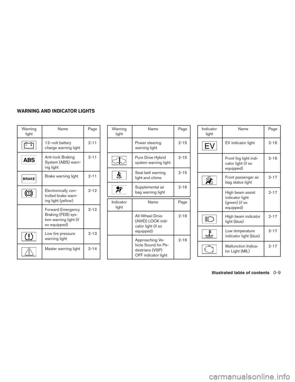
Warninglight Name Page
12–volt battery
charge warning light 2-11
Anti-lock Braking
System (ABS) warn-
ing light2-11
Brake warning light 2-11
Electronically con-
trolled brake warn-
ing light (yellow)2-12
Forward Emergency
Braking (FEB) sys-
tem warning light (if
so equipped)2-12
Low tire pressure
warning light
2-13
Master warning light 2-14
Warning
light Name Page
Power steering
warning light 2-15
Pure Drive Hybrid
system warning light2-15
Seat belt warning
light and chime2-15
Supplemental air
bag warning light2-16
Indicator
light Name Page
All-Wheel Drive
(AWD) LOCK indi-
cator light (if so
equipped) 2-16
Approaching Ve-
hicle Sound for Pe-
destrians (VSP)
OFF indicator light2-16
Indicator
light Name Page
EV indicator light 2-16
Front fog light indi-
cator light (if so
equipped) 2-16
Front passenger air
bag status light
2-17
High beam assist
indicator light
(green) (if so
equipped)2-17
High beam indicator
light (blue)
2-17
Low temperature
indicator light (blue)2-17
Malfunction Indica-
tor Light (MIL)2-17
WARNING AND INDICATOR LIGHTS
Illustrated table of contents0-9
Page 41 of 520
FRONT POWER SEAT ADJUSTMENT
(for driver’s seat)
Operating tips
●The power seat motor has an auto-reset
overload protection circuit. If the motor
stops during operation, wait 30 seconds,
then reactivate the switch.
● Do not operate the power seat switch for a
long period of time when the Hybrid System
is not in the READY mode. This will dis-
charge the vehicle battery. For additional information about automatic driver
positioner operation, refer to “Automatic drive
positioner” in “Pre-driving checks and adjust-
ments” section of this manual.Forward and backward
Moving the switch forward or backward will slide
the seat forward or backward to the desired
position.
Reclining
Move the recline switch backward until the de-
sired angle is obtained. To bring the seatback
forward again, move the switch forward and
move your body forward. The seatback will move
forward.
The reclining feature allows adjustment of the
seatback for occupants of different sizes for
added comfort and to help obtain proper seat
belt fit. For additional information, refer to “Pre-
cautions on seat belt usage” in this section. Also,
the seatback can be reclined to allow occupants
to rest when the vehicle is stopped and the shift
lever is in P (Park) .
LRS2662
1-4Safety—Seats, seat belts and supplemental restraint system
Page 105 of 520
FUEL GAUGE
The gauge indicates theapproximatefuel level
in the tank.
The gauge may move slightly during braking,
turning, acceleration, or going up or down hills.
The gauge needle returns to 0 (Empty) after the
ignition switch is placed in the OFF position.
The low fuel warning message appears in the
vehicle information display when the amount of
fuel in the tank is getting low.
Refill the fuel tank before the gauge regis-
ters 0 (Empty) . The
indicates that the fuel-filler door is
located on the passenger’s side of the vehicle.
CAUTION
● If the vehicle runs out of fuel, theMalfunction Indicator Light (MIL) may
come on. Refuel as soon as possible.
After a few driving trips. the
light
should turn off. If the light remains on
after a few driving trips, have the vehicle
inspected. It is recommended that you
visit a NISSAN dealer for this service.
● For additional information, refer to
“Malfunction Indicator Light (MIL)” in
this section.
ASSIST CHARGE GAUGE
The assist charge gauge indicates the condition
of the electric motor. When the needle is be-
tween the center and “charge” (
�1range) , this
indicates that the electric motor is generating
power to recharge the Li-ion battery.
When the needle is between the center and the
PWR side, this indicates that the electric motor is
powering the drive wheels and the Li-ion battery
is discharging.
LIC2222LIC2544
2-6Instruments and controls