2017 NISSAN QUEST warning lights
[x] Cancel search: warning lightsPage 185 of 520
3-34Pre-driving checks and adjustments
SPA2143
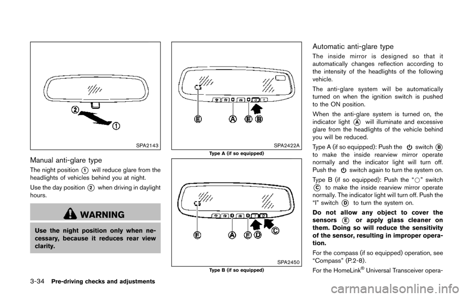
Manual anti-glare type
The night position*1will reduce glare from the
headlights of vehicles behind you at night.
Use the day position
*2when driving in daylight
hours.
WARNING
Use the night position only when ne-
cessary, because it reduces rear view
clarity.
SPA2422A
Type A (if so equipped)
SPA2450Type B (if so equipped)
Automatic anti-glare type
The inside mirror is designed so that it
automatically changes reflection according to
the intensity of the headlights of the following
vehicle.
The anti-glare system will be automatically
turned on when the ignition switch is pushed
to the ON position.
When the anti-glare system is turned on, the
indicator light
*Awill illuminate and excessive
glare from the headlights of the vehicle behind
you will be reduced.
Type A (if so equipped): Push the
switch*B
to make the inside rearview mirror operate
normally and the indicator light will turn off.
Push the
switch again to turn the system on.
Type B (if so equipped): Push the “*” switch
*Cto make the inside rearview mirror operate
normally. The indicator light will turn off. Push the
“I” switch
*Dto turn the system on.
Do not allow any object to cover the
sensors
*Eor apply glass cleaner on
them. Doing so will reduce the sensitivity
of the sensor, resulting in improper opera-
tion.
For the compass (if so equipped) operation, see
“Compass” (P.2-8) .
For the HomeLink
�ŠUniversal Transceiver opera-
Page 380 of 520
SSD0944
INTELLIGENT KEY BATTERY DIS-
CHARGE
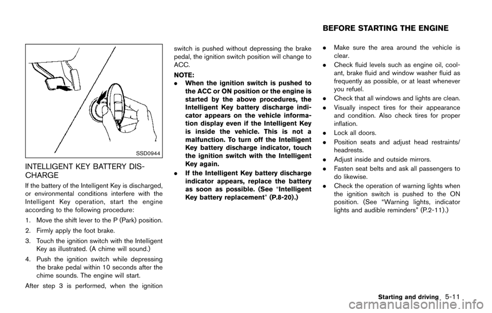
If the battery of the Intelligent Key is discharged,
or environmental conditions interfere with the
Intelligent Key operation, start the engine
according to the following procedure:
1. Move the shift lever to the P (Park) position.
2. Firmly apply the foot brake.
3. Touch the ignition switch with the IntelligentKey as illustrated. (A chime will sound.)
4. Push the ignition switch while depressing the brake pedal within 10 seconds after the
chime sounds. The engine will start.
After step 3 is performed, when the ignition switch is pushed without depressing the brake
pedal, the ignition switch position will change to
ACC.
NOTE:
.
When the ignition switch is pushed to
the ACC or ON position or the engine is
started by the above procedures, the
Intelligent Key battery discharge indi-
cator appears on the vehicle informa-
tion display even if the Intelligent Key
is inside the vehicle. This is not a
malfunction. To turn off the Intelligent
Key battery discharge indicator, touch
the ignition switch with the Intelligent
Key again.
. If the Intelligent Key battery discharge
indicator appears, replace the battery
as soon as possible. (See “Intelligent
Key battery replacement” (P.8-20) .).
Make sure the area around the vehicle is
clear.
. Check fluid levels such as engine oil, cool-
ant, brake fluid and window washer fluid as
frequently as possible, or at least whenever
you refuel.
. Check that all windows and lights are clean.
. Visually inspect tires for their appearance
and condition. Also check tires for proper
inflation.
. Lock all doors.
. Position seats and adjust head restraints/
headrests.
. Adjust inside and outside mirrors.
. Fasten seat belts and ask all passengers to
do likewise.
. Check the operation of warning lights when
the ignition switch is pushed to the ON
position. (See “Warning lights, indicator
lights and audible reminders” (P.2-11) .)
Starting and driving5-11
BEFORE STARTING THE ENGINE
Page 385 of 520
5-16Starting and driving
SSD1177
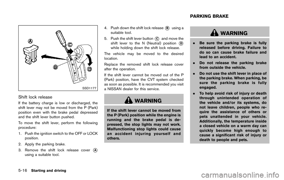
Shift lock release
If the battery charge is low or discharged, the
shift lever may not be moved from the P (Park)
position even with the brake pedal depressed
and the shift lever button pushed.
To move the shift lever, perform the following
procedure:
1. Push the ignition switch to the OFF or LOCKposition.
2. Apply the parking brake.
3. Remove the shift lock release cover
*A
using a suitable tool. 4. Push down the shift lock release
*Busing a
suitable tool.
5. Push the shift lever button
*Cand move the
shift lever to the N (Neutral) position
*D
while holding down the shift lock release.
The vehicle may be moved to the desired
location.
Replace the removed shift lock release cover
after the operation.
If the shift lever cannot be moved out of the P
(Park) position, have the CVT system checked
as soon as possible. It is recommended you visit
a NISSAN dealer for this service.
WARNING
If the shift lever cannot be moved from
the P (Park) position while the engine is
running and the brake pedal is de-
pressed, the stop lights may not work.
Malfunctioning stop lights could cause
an accident injuring yourself and
others.
WARNING
. Be sure the parking brake is fully
released before driving. Failure to
do so can cause brake failure and
lead to an accident.
. Do not release the parking brake
from outside the vehicle.
. Do not use the shift lever in place of
the parking brake. When parking, be
sure the parking brake is fully
engaged.
. To help avoid risk of injury or death
through unintended operation of
the vehicle and/or its systems, do
not leave children, people who re-
quire the assistance of others or
pets unattended in your vehicle.
Additionally, the temperature inside
a closed vehicle on a warm day can
quickly become high enough to
cause a significant risk of injury or
death to people and pets.
PARKING BRAKE
Page 407 of 520
6-2In case of emergency
SIC2574
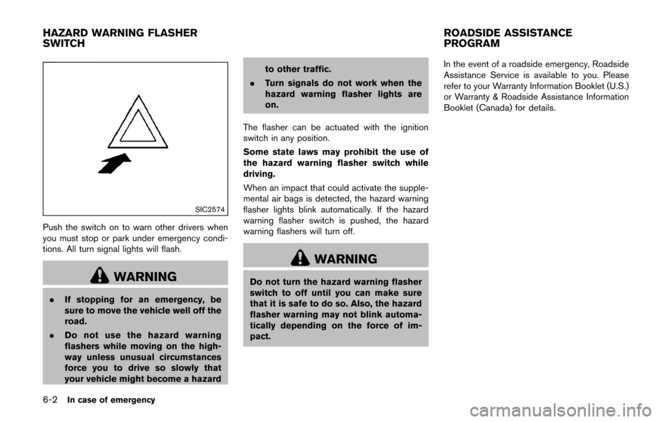
Push the switch on to warn other drivers when
you must stop or park under emergency condi-
tions. All turn signal lights will flash.
WARNING
.If stopping for an emergency, be
sure to move the vehicle well off the
road.
. Do not use the hazard warning
flashers while moving on the high-
way unless unusual circumstances
force you to drive so slowly that
your vehicle might become a hazard to other traffic.
. Turn signals do not work when the
hazard warning flasher lights are
on.
The flasher can be actuated with the ignition
switch in any position.
Some state laws may prohibit the use of
the hazard warning flasher switch while
driving.
When an impact that could activate the supple-
mental air bags is detected, the hazard warning
flasher lights blink automatically. If the hazard
warning flasher switch is pushed, the hazard
warning flashers will turn off.
WARNING
Do not turn the hazard warning flasher
switch to off until you can make sure
that it is safe to do so. Also, the hazard
flasher warning may not blink automa-
tically depending on the force of im-
pact. In the event of a roadside emergency, Roadside
Assistance Service is available to you. Please
refer to your Warranty Information Booklet (U.S.)
or Warranty & Roadside Assistance Information
Booklet (Canada) for details.
HAZARD WARNING FLASHER
SWITCH
ROADSIDE ASSISTANCE
PROGRAM
Page 408 of 520
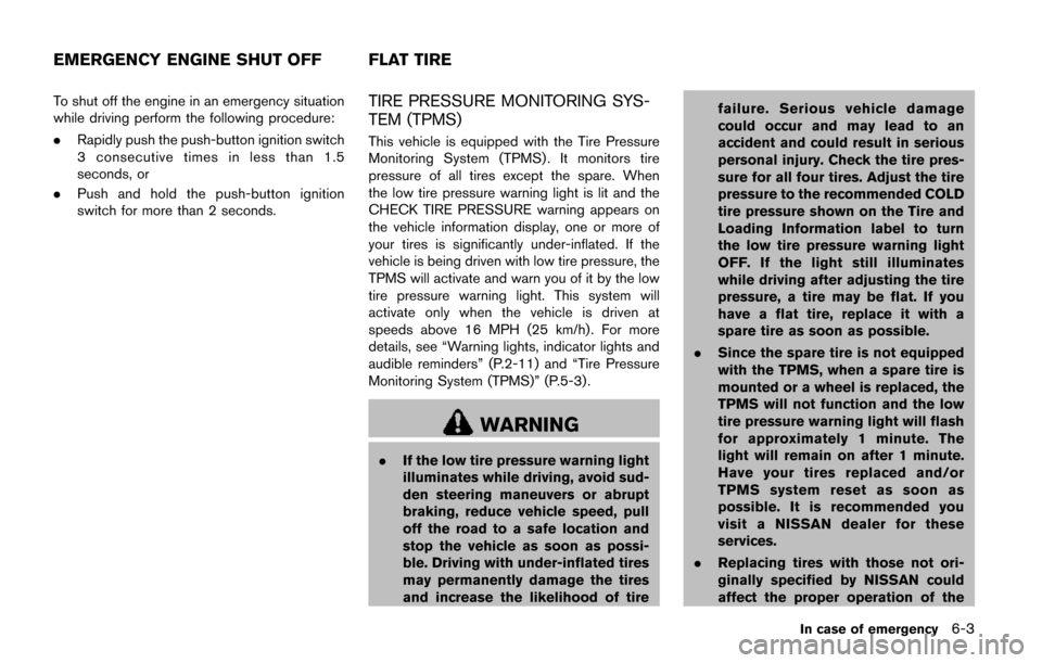
To shut off the engine in an emergency situation
while driving perform the following procedure:
.Rapidly push the push-button ignition switch
3 consecutive times in less than 1.5
seconds, or
. Push and hold the push-button ignition
switch for more than 2 seconds.TIRE PRESSURE MONITORING SYS-
TEM (TPMS)
This vehicle is equipped with the Tire Pressure
Monitoring System (TPMS) . It monitors tire
pressure of all tires except the spare. When
the low tire pressure warning light is lit and the
CHECK TIRE PRESSURE warning appears on
the vehicle information display, one or more of
your tires is significantly under-inflated. If the
vehicle is being driven with low tire pressure, the
TPMS will activate and warn you of it by the low
tire pressure warning light. This system will
activate only when the vehicle is driven at
speeds above 16 MPH (25 km/h) . For more
details, see “Warning lights, indicator lights and
audible reminders” (P.2-11) and “Tire Pressure
Monitoring System (TPMS)” (P.5-3) .
WARNING
.If the low tire pressure warning light
illuminates while driving, avoid sud-
den steering maneuvers or abrupt
braking, reduce vehicle speed, pull
off the road to a safe location and
stop the vehicle as soon as possi-
ble. Driving with under-inflated tires
may permanently damage the tires
and increase the likelihood of tire failure. Serious vehicle damage
could occur and may lead to an
accident and could result in serious
personal injury. Check the tire pres-
sure for all four tires. Adjust the tire
pressure to the recommended COLD
tire pressure shown on the Tire and
Loading Information label to turn
the low tire pressure warning light
OFF. If the light still illuminates
while driving after adjusting the tire
pressure, a tire may be flat. If you
have a flat tire, replace it with a
spare tire as soon as possible.
. Since the spare tire is not equipped
with the TPMS, when a spare tire is
mounted or a wheel is replaced, the
TPMS will not function and the low
tire pressure warning light will flash
for approximately 1 minute. The
light will remain on after 1 minute.
Have your tires replaced and/or
TPMS system reset as soon as
possible. It is recommended you
visit a NISSAN dealer for these
services.
. Replacing tires with those not ori-
ginally specified by NISSAN could
affect the proper operation of the
In case of emergency6-3
EMERGENCY ENGINE SHUT OFF FLAT TIRE
Page 416 of 520

.Whenever working on or near a
battery, always wear suitable eye
protectors (for example, goggles or
industrial safety spectacles) and
remove rings, metal bands, or any
other jewelry. Do not lean over the
battery when jump starting.
. Do not attempt to jump start a
frozen battery. It could explode
and cause serious injury.
. Your vehicle has an automatic en-
gine cooling fan. It could come on at
any time. Keep hands and other
objects away from it.
SCE0969
WARNING
Always follow the instructions below.
Failure to do so could result in damage
to the charging system and cause
personal injury.
1. If the booster battery is in another vehicle
*B, position the two vehicles (*Aand*B)
to bring their batteries into close proximity to
each other.
Do not allow the two vehicles to touch. 2. Apply the parking brake. Move the shift lever
to the P (Park) position. Switch off all
unnecessary electrical systems (lights, hea-
ter, air conditioner, etc.) .
3. Remove vent caps on the battery (if so equipped) . Cover the battery with a firmly
wrung out moist cloth to reduce explosion
hazard.
4. Connect jumper cables in the sequence as illustrated (
*1?*2?*3?*4).
If the battery is discharged, the ignition
switch cannot be moved from the OFF
position. Connect the jumper cables to
the booster vehicle
*Bbefore pushing
the ignition switch.
CAUTION
. Always connect positive (+) to posi-
tive (+) and negative (�í) to body
ground (for example, as illustrated) ,
not to the battery.
. Make sure the jumper cables do not
touch moving parts in the engine
compartment and that the cable
clamps do not contact any other
metal.
In case of emergency6-11
Page 430 of 520
8 Do-it-yourself
Maintenance precautions ........................................................ 8-2
Engine compartment check locations .................................. 8-3VQ35DE engine .................................................................. 8-3
Engine cooling system ............................................................. 8-4 Checking engine coolant level ......................................... 8-5
Changing engine coolant .................................................. 8-5
Engine oil ........................................................................\
............ 8-5 Checking engine oil level .................................................. 8-5
Changing engine oil and filter .......................................... 8-6
Continuously Variable Transmission (CVT) fluid ............... 8-8
Power steering fluid .................................................................. 8-8
Brake fluid ........................................................................\
........... 8-9
Window washer fluid ............................................................ 8-10
Battery ........................................................................\
............... 8-10 Jump starting ..................................................................... 8-12
Variable voltage control system .......................................... 8-12
Drive belt ........................................................................\
.......... 8-12
Spark plugs ........................................................................\
..... 8-13 Replacing spark plugs .................................................... 8-13
Air cleaner ........................................................................\
........ 8-14 Windshield wiper blades ..................................................... 8-14
Cleaning ........................................................................\
... 8-14
Replacing ........................................................................\
. 8-15
Washer nozzle ................................................................ 8-16
Rear window wiper blade ................................................... 8-17
Brakes ........................................................................\
.............. 8-17
Self-adjusting brakes .................................................... 8-17
Brake pad wear warning .............................................. 8-17
Fuses ........................................................................\
................ 8-18 Engine compartment ..................................................... 8-18
Passenger compartment .............................................. 8-19
Intelligent Key battery replacement ................................... 8-20
Lights ........................................................................\
................ 8-22
Headlights ........................................................................\
8-22
Exterior and interior lights ............................................ 8-24
Wheels and tires ................................................................... 8-27
Tire pressure ................................................................... 8-27
Tire labeling ..................................................................... 8-31
Types of tires ................................................................... 8-33
Tire chains ....................................................................... 8-33
Changing wheels and tires .......................................... 8-35
Page 452 of 520
Replacing
If replacement is required, it is recommended
you visit your NISSAN dealer for this service.
Xenon headlight model:
WARNING
HIGH VOLTAGE
When xenon headlights are on, they
produce a high voltage. To prevent an
electric shock, never attempt to modify
or disassemble. It is recommended to
have your xenon headlights replaced at
a NISSAN dealer. For additional infor-
mation, see “Headlight and turn signal
switch” (P.2-33) .
Halogen headlight model:
The headlight is a semi-sealed beam type which
uses a replaceable headlight (halogen) bulb.
CAUTION
. Do not leave the bulb out of the
headlight reflector for a long period
of time. Dust, moisture, smoke, etc.
entering the headlight body may affect bulb performance.
. High pressure halogen gas is sealed
inside the halogen bulb. The bulb
may break if the glass envelope is
scratched or the bulb is dropped.
. Only touch the plastic base when
handling the bulb. Never touch the
glass envelope.
. Aiming is not necessary after repla-
cing the bulb. When aiming adjust-
ment is necessary, it is
recommended you visit a NISSAN
dealer for this service.
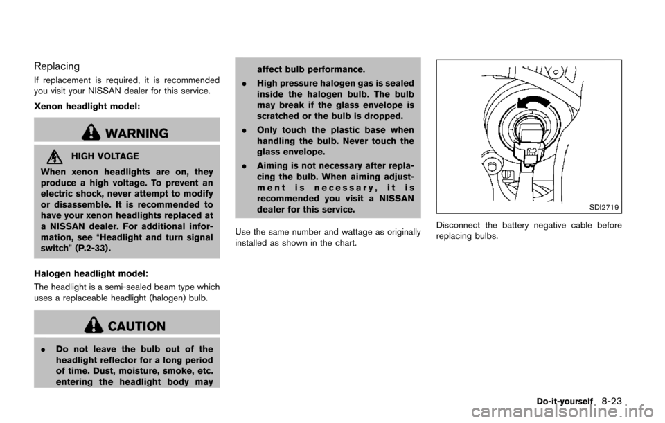
Use the same number and wattage as originally
installed as shown in the chart.
SDI2719
Disconnect the battery negative cable before
replacing bulbs.
Do-it-yourself8-23