Page 146 of 466

WARNING
●Do not use the HomeLink® Universal
Transceiver with any garage door
opener that lacks safety stop and re-
verse features as required by federal
safety standards. (These standards be-
came effective for opener models
manufactured after April 1, 1982) . A ga-
rage door opener which cannot detect
an object in the path of a closing garage
door and then automatically stop and
reverse, does not meet current federal
safety standards. Using a garage door
opener without these features in-
creases the risk of serious injury or
death.
● During the programming procedure
your garage door or security gate will
open and close (if the transmitter is
within range) . Make sure that people or
objects are clear of the garage door,
gate, etc. that you are programming.
● Your vehicle’s engine should be turned
off while programming the HomeLink®
Universal Transceiver.
PROGRAMMING HOMELINK®
If you have any questions or are having difficulty
programming your HomeLink® buttons, refer to
the HomeLink® web site at: www.homelink.com
or call 1-800-355-3515.
NOTE:
Place the ignition switch in the ACC posi-
tion (if so equipped) when programming
HomeLink®. It is also recommended that a
new battery be placed in the hand-held
transmitter of the device being pro-
grammed to HomeLink® for quicker pro-
gramming and accurate transmission of
the radio frequency. 1. Position the end of your hand-held transmit-
ter 1–3 in (2–8 cm) away from the
HomeLink® surface, keeping the
HomeLink® indicator light
�1in view.
Page 164 of 466
CAUTION
When locking the doors using the Intelli-
gent Key, be sure not to leave the key in
the vehicle.
Locking doors
1. Place the ignition switch in the LOCK posi-tion.
2. Close all doors.
3. Press the
Page 182 of 466

CAUTION
For vehicles with automatic drive posi-
tioner: Failure to reset the tilt and tele-
scoping functions of the steering wheel,
after the vehicle’s battery has been dis-
charged, may prevent the steering wheel
position from being adjusted.
For vehicles with automatic drive positioner: Both
the tilt and telescopic steering operation must be
reset after the vehicle’s battery has been dis-
charged in order to prevent the tilt and telescopic
operation from locking in one position. When the
battery has been recharged or replaced, perform
the following:
● For tilt operation, adjust the switch
�1so the
steering wheel moves to the highest position
�2that can be reached.
● For telescopic operation, adjust the switch
�1so the steering wheel moves to the most
forward and backward position
�3that can
be reached.
Performing these operations resets the range of
the steering wheel’s tilt and telescopic function.
Entry/Exit function
The automatic drive positioner system will make
the steering wheel move up automatically when
the driver’s door is opened and the ignition
switch is in the LOCK position. This lets the driver
get into and out of the seat more easily. The
steering wheel moves back into position when
the driver’s door is closed and the ignition switch
is pushed.
For additional information, refer to “Automatic
drive positioner” in this section.
Page 203 of 466
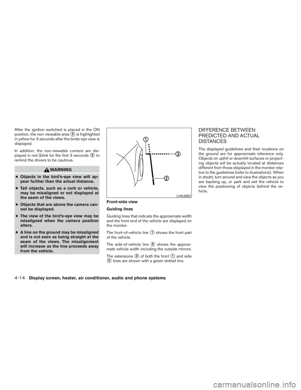
After the ignition switched is placed in the ON
position, the non-viewable area
�2is highlighted
in yellow for 3 seconds after the birds-eye view is
displayed.
In addition, the non-viewable corners are dis-
played in red (blink for the first 3 seconds
�3to
remind the drivers to be cautious.
Page 261 of 466

Additional information:● Since the spare tire is not equipped with the
TPMS, the TPMS does not monitor the tire
pressure of the spare tire.
● The TPMS will activate only when the vehicle
is driven at speeds above 16 mph (25 km/h).
Also, this system may not detect a sudden
drop in tire pressure (for example, a flat tire
while driving) .
● The low tire pressure warning light does not
automatically turn off when the tire pressure
is adjusted. After the tire is inflated to the
recommended pressure, the vehicle must be
driven at speeds above 16 mph (25 km/h) to
activate the TPMS and turn off the low tire
pressure warning light. Use a tire pressure
gauge to check the tire pressure.
● The “Tire Pressure Low — Add Air” warning
appears in the vehicle information display
when the low tire pressure warning light is
illuminated and low tire pressure is detected.
The “Tire Pressure Low — Add Air” warning
turns off when the low tire pressure warning
light turns off.
●
The “Tire Pressure Low — Add Air” warning
appears each time the ignition switch is placed
in the ON position as long as the low tire
pressure warning light remains illuminated.
● The “Tire Pressure Low — Add Air” warning
does not appear if the low tire pressure
warning light illuminates to indicate a TPMS
malfunction.
● Tire pressure rises and falls depending on
the heat caused by the vehicle’s operation
and the outside temperature. Do not reduce
the tire pressure after driving because the
tire pressure rises after driving. Low outside
temperature can lower the temperature of
the air inside the tire which can cause a
lower tire inflation pressure. This may cause
the low tire pressure warning light to illumi-
nate. If the warning light illuminates, check
the tire pressure for all four tires.
● The Tire and Loading Information label is
located in the driver’s door opening.
● You can also check the pressure of all tires
(except the spare tire) on the vehicle infor-
mation display screen. The order of the tire
pressure figures displayed on the screen
corresponds with the actual order of the tire
position.
For additional information, refer to “Low tire pres-
sure warning light” in the “Instruments and con-
trols” section and “Tire Pressure Monitoring Sys-
tem (TPMS)” in the “In case of emergency”
section of this manual.
Page 269 of 466

The operating range of the engine start function
is inside of the vehicle
�1.
● The luggage area is not included in the op-
erating range, but the Intelligent Key may
function.
● If the Intelligent Key is placed on the instru-
ment panel, inside the glove box, storage bin
or door pocket, the Intelligent Key may not
function.
● If the Intelligent Key is placed near the door
or window outside the vehicle, the Intelligent
Key may function.
PUSH-BUTTON IGNITION SWITCH
POSITIONS
LOCK (Normal parking position)
The ignition switch can only be locked in this
position.
The ignition switch will be unlocked when it is
pushed to the ACC position while carrying the
Intelligent Key.
The ignition switch will lock when any door is
opened or closed with the ignition switched off.
ACC (Accessories)
This position activates electrical accessories,
such as the radio, when the engine is not running. ACC has a battery saver feature that will turn the
ignition switch to the OFF position after a period
of time under the following conditions:
● All doors are closed.
● Shift lever is in P (Park) .
● Hazard lamps are off.
● Turn signals are off.
The battery saver feature will be canceled if any of
the following occur: ● Any door is opened.
● Shift lever is moved out of P (Park) .
● Ignition switch changes position.
● Hazard lamps are turned on.
ON (Normal operating position)
This position turns on the ignition system and
electrical accessories.
ON has a battery saver feature that will turn the
ignition switch to the OFF position, if the vehicle
is not running, after some time under the follow-
ing conditions: ● All doors are closed.
● Shift lever is in P (Park) .
● Hazard lamps are off. ●
Turn signals are off.
The battery saver feature will be canceled if any of
the following occur: ● Any door is opened.
● Shift lever is moved out of the P (Park)
position.
● Ignition switch changes position.
● Hazard lamps are turned on.
● Turn signals are turned on.
Page 272 of 466
the accelerator pedal by depressing the
brake pedal and pushing the push-button
ignition switch to start the engine. If the
engine starts, but fails to run, repeat the
above procedure.
Page 277 of 466
Shift lock release
If the battery charge is low or discharged, the
shift lever may not be moved from the P (Park)
position even with the brake pedal depressed
and the shift lever button pressed. To move the
shift lever, perform the following procedure:1. Place the ignition switch in the OFF or LOCK position.
2. Apply the parking brake.
3. Remove the shift lock release cover using a suitable tool.
4. Push down the shift lock release using a suitable tool. 5. Press the shift lever button and move the
shift lever to the N (Neutral) position while
holding down the shift lock release. The
vehicle may be moved to the desired loca-
tion. Replace the removed shift lock release
cover after the operation. If the shift lever
cannot be moved out of the P (Park) posi-
tion, have the CVT system checked as soon
as possible. It is recommended that you visit
a NISSAN dealer for this service.


position even with the brake pedal depressed
and the shift lever button pressed. To mo")