2017 NISSAN LEAF ESP
[x] Cancel search: ESPPage 1 of 44
2017 LEAF
First Responder’s Guide
Page 2 of 44
Foreword
This
manual describes first response operations and important safetyrelated warnings for this vehicle.
This vehicle is an electrically driven car equipped with a high-voltage battery pack. Failure to follow
recommended practices during emergency responses will cause death or serious personal
injury.
Please read this manual in advance in order to understand the features of this vehicle and to help you deal
with incidents involving this vehicle. Follow the procedures in order to help assure a safe and successful
first response operation.
This manual is periodically updated. If you are not viewing this manual on the Nissan web site, we urge you
to go to www.nissanusa.com orwww.nissan-techinfo.com to make sure you have the most recent version of
this
manual.
NISSAN EMERGENCY CONTACT INFORMATION • Nissan EV Customer Support: 1-877-664-2738 (Hours of operation are Monday-Friday 7am -7pm, Saturday 8am - 4:30pm Central time zone)
• Nissan Consumer Affairs: 1-800-647-7261 (US) or 1-800-387-0122 (Canada) (Hours of operation are 8am - 5pm (Monday-Friday) Eastern, Central and Pacific time zones)
IMPORTANT INFORMATION ABOUT THIS MANUAL
You may see various symbols in this manual. They have the following meanings: This symbol is used to inform you of an operation which will result in death or serious personal injury if
instructions
are not followed.
Example: Touching high-voltage components without using the appropriate protective equipment will result
in electrocution. This symbol is used to inform you of an operation which may cause death or serious personal injury if
instructions
are not followed.This symbol is used to inform you of an operation which may cause personal injury or component damage if
instructions
are not followed.
Please note that there may be differences between this manual and the vehicle specification due to
specification changes.
FRG–2
Page 3 of 44
Table of Contents
FOREWORD
. . . . . . . . . . . . . . . . . . . . . . . . . . . . . . . . . . . . . . . . . . . . . . . . . . . . . . . . . . . . . . . . . . . FRG–2
NISSAN EMERGENCY CONTACT INFORMATION . . . . . . . . . . . . . . . . . . . . . . . . . . . . . . . . . . FRG–2
IMPORTANT INFORMATION ABOUT THIS MANUAL . . . . . . . . . . . . . . . . . . . . . . . . . . . . . . . . . FRG–2
1. ABOUT THE NISSAN LEAF® . . . . . . . . . . . . . . . . . . . . . . . . . . . . . . . . . . . . . . . . . . . . . . . . . . . FRG–4
1-1 LEAF IDENTIFICATION . . . . . . . . . . . . . . . . . . . . . . . . . . . . . . . . . . . . . . . . . . . . . . . . . . . . FRG–51-1.1 EXTERIOR . . . . . . . . . . . . . . . . . . . . . . . . . . . . . . . . . . . . . . . . . . . . . . . . . . . . . . . . . FRG–5
1-1.2 INTERIOR COMPONENT LOCATION . . . . . . . . . . . . . . . . . . . . . . . . . . . . . . . . . . . . FRG–6
1-2 VEHICLE IDENTIFICATION NUMBER (VIN) LAYOUT . . . . . . . . . . . . . . . . . . . . . . . . . . . . . FRG–7
1-3 WARNING AND INDICATOR LAMP INFORMATION . . . . . . . . . . . . . . . . . . . . . . . . . . . . . . FRG–7
2. BASIC HIGH-VOLTAGE SYSTEM AND 12-VOLT SYSTEM INFORMATION . . . . . . . . . . . . . . . FRG–8 2-1 HIGH-VOLTAGE-RELATED AND 12-VOLT-RELATED COMPONENT LOCATIONS AND DESCRIPTIONS . . . . . . . . . . . . . . . . . . . . . . . . . . . . . . . . . . . . . . . . . . . . . . . . . . . . . FRG–8
2-1.1 HIGH-VOLTAGE BATTERY PACK SPECIFICATIONS . . . . . . . . . . . . . . . . . . . . . . . FRG–10
2-2 HIGH-VOLTAGE SAFETY MEASURES . . . . . . . . . . . . . . . . . . . . . . . . . . . . . . . . . . . . . . . FRG–10 2-2.1 WARNING LABEL . . . . . . . . . . . . . . . . . . . . . . . . . . . . . . . . . . . . . . . . . . . . . . . . . . FRG–10
2-3 HIGH-VOLTAGE CIRCUIT SHUT-OFF SYSTEM . . . . . . . . . . . . . . . . . . . . . . . . . . . . . . . . FRG–10
2-4 PREVENTING ELECTRICAL SHOCK . . . . . . . . . . . . . . . . . . . . . . . . . . . . . . . . . . . . . . . . FRG–11
2-5 EMERGENCY MEDICAL EQUIPMENT . . . . . . . . . . . . . . . . . . . . . . . . . . . . . . . . . . . . . . . FRG–11
3. EMERGENCY RESPONSE STEPS . . . . . . . . . . . . . . . . . . . . . . . . . . . . . . . . . . . . . . . . . . . . . FRG–12 3-1 PREPARATION ITEMS . . . . . . . . . . . . . . . . . . . . . . . . . . . . . . . . . . . . . . . . . . . . . . . . . . . FRG–133-1.1 PERSONAL PROTECTIVE EQUIPMENT (PPE) PROTECTIVE WEAR CONTROL . . . . . . . . . . . . . . . . . . . . . . . . . . . . . . . . . . . . . . . . . . . . . . . . . . . . . . . . FRG–14
3-1.2 DAILY INSPECTION . . . . . . . . . . . . . . . . . . . . . . . . . . . . . . . . . . . . . . . . . . . . . . . . FRG–14
3-1.3 INSULATED TOOLS . . . . . . . . . . . . . . . . . . . . . . . . . . . . . . . . . . . . . . . . . . . . . . . . FRG–14
3-2 VEHICLE IMMOBILIZATION AND STABILIZATION . . . . . . . . . . . . . . . . . . . . . . . . . . . . . . FRG–15
3-3 HOW TO HANDLE A DAMAGED VEHICLE AT AN ACCIDENT SCENE . . . . . . . . . . . . . FRG–16 3-3.1 HIGH-VOLTAGE SYSTEM SHUT-DOWN PROCEDURES . . . . . . . . . . . . . . . . . . . FRG–17
3-3.2 WATER SUBMERSION . . . . . . . . . . . . . . . . . . . . . . . . . . . . . . . . . . . . . . . . . . . . . . FRG–28
3-3.3 VEHICLE FIRE . . . . . . . . . . . . . . . . . . . . . . . . . . . . . . . . . . . . . . . . . . . . . . . . . . . . . FRG–28
3-3.4 CUTTING THE VEHICLE BODY . . . . . . . . . . . . . . . . . . . . . . . . . . . . . . . . . . . . . . . FRG–29
3-3.5 HIGH-VOLTAGE BATTERY DAMAGE AND FLUID LEAKS . . . . . . . . . . . . . . . . . . . FRG–36
3-3.6 ACCESSING THE OCCUPANTS . . . . . . . . . . . . . . . . . . . . . . . . . . . . . . . . . . . . . . FRG–37
3-4 STORING THE VEHICLE . . . . . . . . . . . . . . . . . . . . . . . . . . . . . . . . . . . . . . . . . . . . . . . . . . FRG–38
4. EMERGENCY QUICK REFERENCE GUIDE . . . . . . . . . . . . . . . . . . . . . . . . . . . . . . . . . . . . . . . FRG–39
FRG–3
Page 10 of 44
2-1.1 High-Voltage Battery Pack Specifications
High-voltage battery voltage
360V nominal
(240V - 398.4V usable range)
Number of high-voltage battery modules in the pack 48
High-voltage battery dimensions 60.91 x 46.77 x 10.39 in. (1547 x 1188 x 264 mm)
High-voltage battery weight US: 648 lbs (294 kg)
Canada: 653 lbs (296 kg)
2-2 High-Voltage Safety Measures Circuit insulation
The high-voltage positive (+) and negative (-) circuits are insulated from the
metal
chassis.
Reducing the risk of
electrocution The high-voltage components and harnesses have insulated cases or orange-
colored coverings which provide insulation and easy identification.
The high-voltage battery case is electrically connected to the vehicle ground.
This connection helps protect the vehicle occupants and emergency
responders from high-voltage electrical shock.
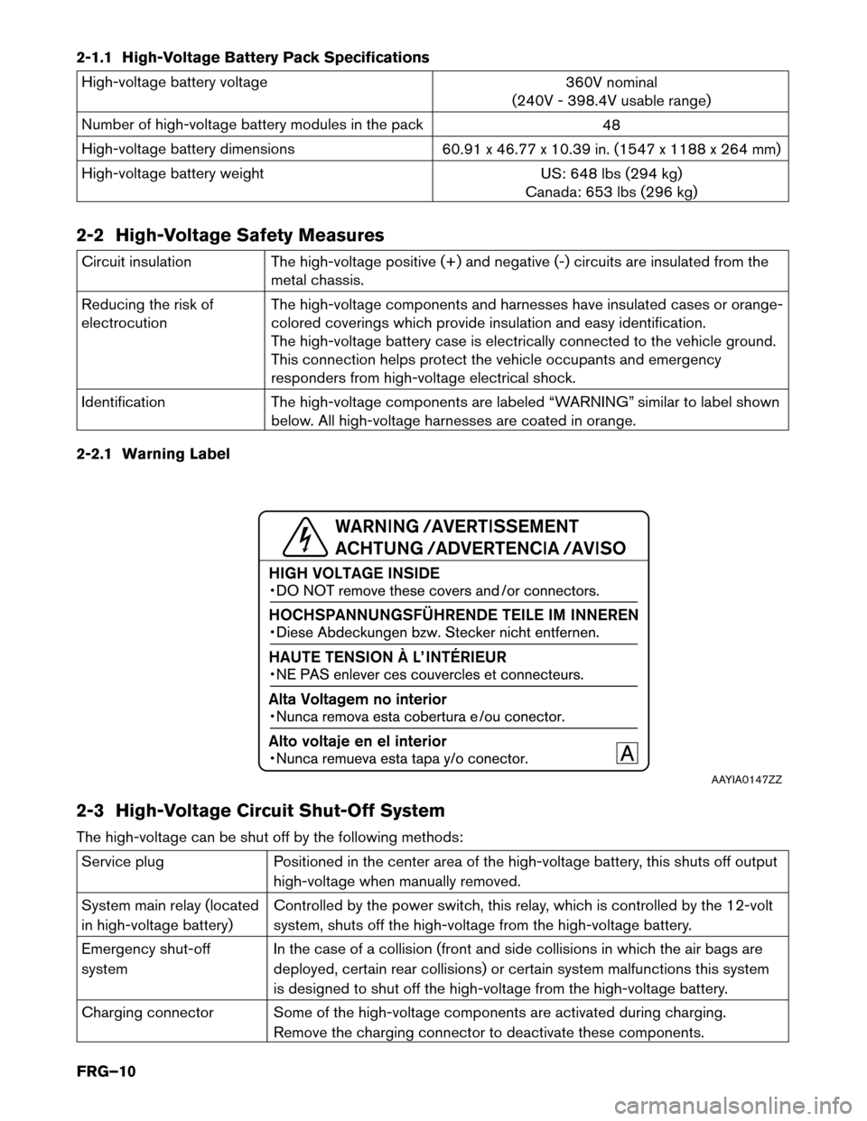
Identification The high-voltage components are labeled “WARNING” similar to label shown
below. All high-voltage harnesses are coated in orange.
2-2.1 Warning Label
2-3 High-Voltage Circuit Shut-Off System
The high-voltage can be shut off by the following methods: Service plug
Positioned in the center area of the high-voltage battery, this shuts off output
high-voltage
when manually removed.
System main relay (located
in high-voltage battery) Controlled by the power switch, this relay, which is controlled by the 12-volt
system, shuts off the high-voltage from the high-voltage battery.
Emergency shut-off
system In the case of a collision (front and side collisions in which the air bags are
deployed, certain rear collisions) or certain system malfunctions this system
is designed to shut off the high-voltage from the high-voltage battery.
Charging connector Some of the high-voltage components are activated during charging. Remove the charging connector to deactivate these components. AAYIA0147ZZ
FRG–10
Page 12 of 44
3. Emergency Response Steps
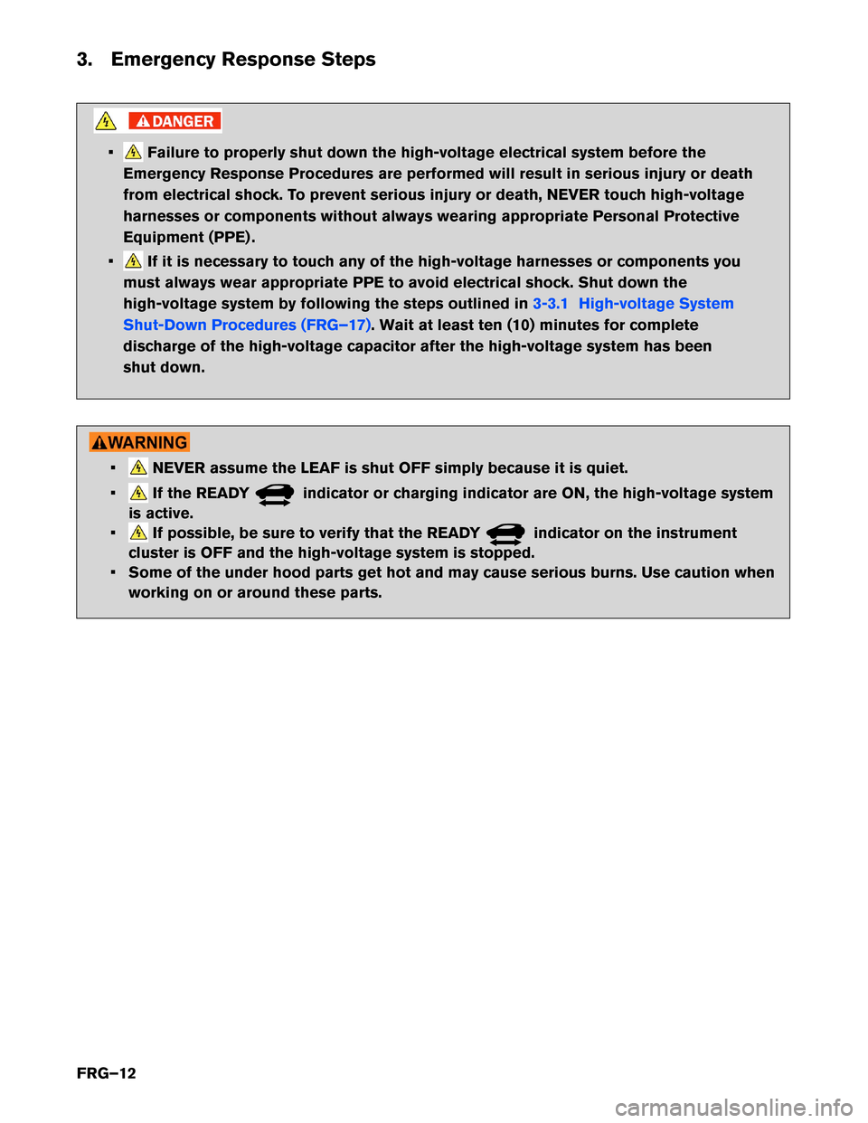
• Failure to properly shut down the high-voltage electrical system before the
Emergency Response Procedures are performed will result in serious injury or death
from electrical shock. To prevent serious injury or death, NEVER touch high-voltage
harnesses or components without always wearing appropriate Personal Protective
Equipment (PPE) .
• If it is necessary to touch any of the high-voltage harnesses or components you
must
always wear appropriate PPE to avoid electrical shock. Shut down the
high-voltage system by following the steps outlined in 3-3.1 High-voltage System
Shut-Down
Procedures (FRG–17) . Wait at least ten (10) minutes for complete
discharge
of the high-voltage capacitor after the high-voltage system has been
shut down. • NEVER assume the LEAF is shut OFF simply because it is quiet.
• If the READY indicator or charging indicator are ON, the high-voltage system
is
active.
• If possible, be sure to verify that the READY indicator on the instrument
cluster
is OFF and the high-voltage system is stopped.
• Some of the under hood parts get hot and may cause serious burns. Use caution when working on or around these parts.
FRG–12
Page 14 of 44
3-1.1 Personal Protective Equipment (PPE) Protective Wear Control
Perform
an inspection of the Personal Protective Equipment (PPE) items before beginning work. Do not use
any damaged PPE items.
3-1.2 Daily Inspection
This inspection is performed before and after use. The responder who will be using the items should
perform the inspection and check for deterioration and damage. • Insulated rubber gloves should be inspected for scratches, holes and tears. (Visual check and airleakage test)
• Insulated safety boots should be inspected for holes, damage, nails, metal pieces, wear or other problems on the soles. (Visual check)
• Insulated rubber sheet should be inspected for tears. (Visual check)
3-1.3 Insulated Tools
When performing work at locations where high-voltage is applied (such as terminals) , use insulated tools
meeting 1,000V/300A specifications.
FRG–14
Page 16 of 44
3-3 How to Handle a Damaged Vehicle at an Accident Scene
NO
TE:
If any air bags have deployed in the following 3 situations, the high-voltage (HV) system has
been designed to automatically shut off at the time of deployment.
The Nissan LEAF high-voltage system incorporates capacitors which are energized whenever the high-
voltage system is on. If the high-voltage system is shut down (either through one of the built-in automatic
mechanisms or manually through one of the procedures explained in this FRG) , the capacitors will begin to
gradually discharge. After 5 minutes, the voltage level will have dropped below 60V, and complete
discharge requires approximately 10 minutes after high-voltage system shut down. It is within
this period of time that responders must be most cautious.
When arriving to an incident involving a Nissan LEAF, the vehicle should be approached with caution and
inspected for the level of damage. In addition to overall vehicle condition (location and severity of body
damage, air bag deployment, etc.) , the high-voltage system should be assessed specifically. The locations
of the high-voltage component parts are illustrated in this FRG. Refer to 2-1 High-Voltage-Related and
12-volt-Related
Component Locations and Descriptions (FRG–8) . Appropriate Personal Protective
Equipment
(PPE) must always be worn when approaching a vehicle of unknown condition, as described
in this FRG.
Situation 1) High-voltage system intact, occupants can be accessed without extrication tools
The HV system can be shut down by following the procedures in this guide, while wearing appropriate PPE.
After HV system shut down, occupant assistance can begin immediately, and no wait period is necessary.
Situation 2) High-voltage system intact, occupants cannot be accessed without extrication tools
The HV system can be shut down by following the procedure in this guide, while wearing appropriate PPE.
After HV system shut down, absolute care must be taken not to cut through or damage any HV system
wiring, battery or components within ten (10) minutes of HV system shut down, but occupant
assistance operations using extrication equipment can begin immediately. The locations of the HV
components are illustrated in this guide.
Situation 3) High-voltage (HV) system damaged
If there is any evidence that the HV system has been compromised (such as arcing/sparking, orange wiring
harnesses cut or damaged, HV component casings damaged, etc.) , the responder may still be at risk of
high-voltage exposure. The vehicle must be approached with extreme caution prior to initiating any system
shut down procedures or rendering assistance to occupants. Appropriate PPE must always be worn as
described in this guide, and the ten (10) minute wait time must be observed after HV system shut
down in order to ensure the system is de-energized.
In rare situations where vehicle damage is very severe, HV system shut down procedures as described in
this guide may not work. In these instances extreme caution and appropriate risk management must be
followed to prevent shock or electrocution to the responder or occupant.
FRG–16
Page 17 of 44
3-3.1 High-voltage System Shut-Down Procedures
Any
of the following procedures can shut down and isolate the high-voltage system. The first response
operation should only begin after shutting down the high-voltage system. If the vehicle is heavily damaged,
for example the high-voltage battery is deformed, broken or cracked, appropriate Personal Protective
Equipment (PPE) must always be used and the high-voltage battery and high-voltage components must not
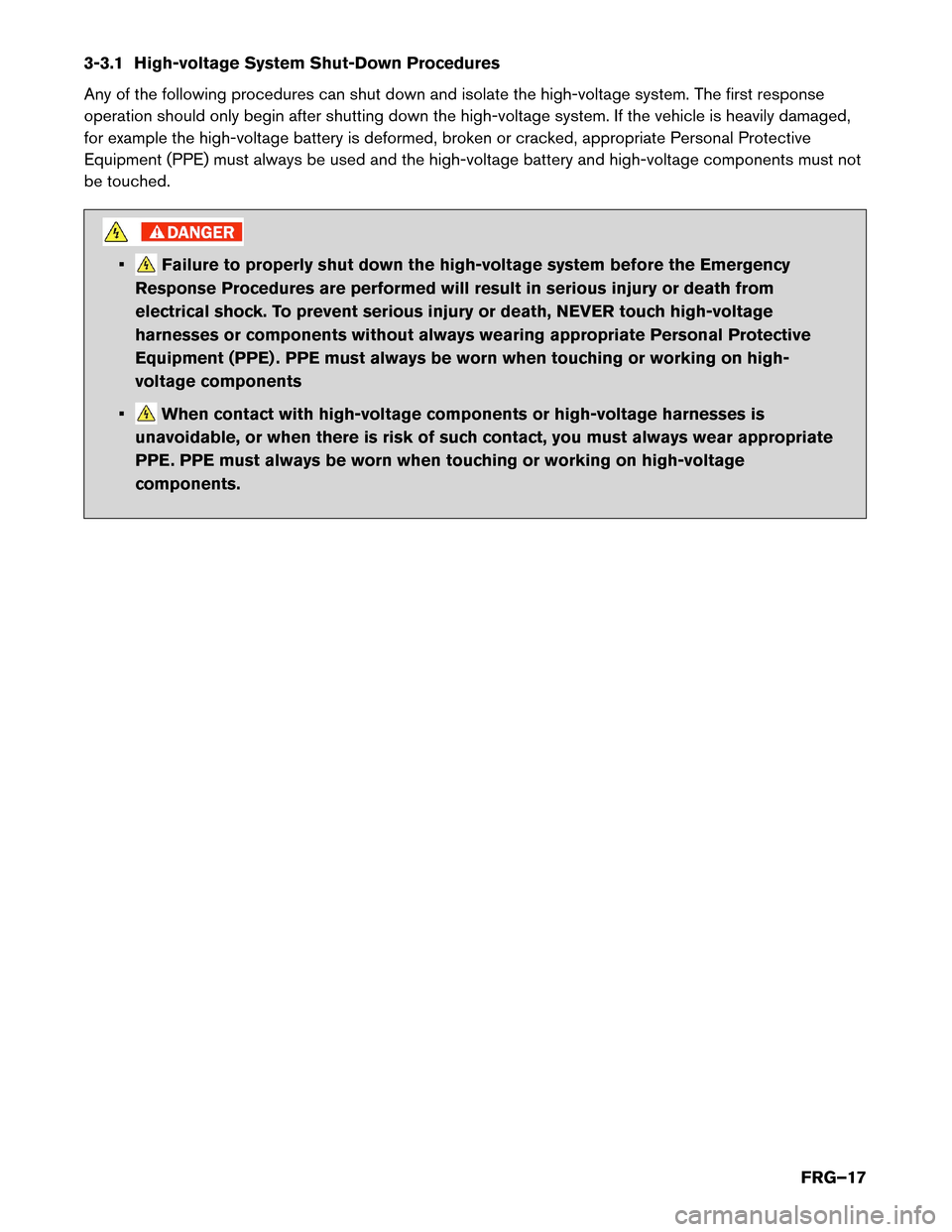
be touched. • Failure to properly shut down the high-voltage system before the Emergency
Response
Procedures are performed will result in serious injury or death from
electrical shock. To prevent serious injury or death, NEVER touch high-voltage
harnesses or components without always wearing appropriate Personal Protective
Equipment (PPE) . PPE must always be worn when touching or working on high-
voltage components
• When contact with high-voltage components or high-voltage harnesses is
unavoidable,
or when there is risk of such contact, you must always wear appropriate
PPE. PPE must always be worn when touching or working on high-voltage
components.
FRG–17