2017 NISSAN JUKE coolant
[x] Cancel search: coolantPage 19 of 416

0-10Illustrated table of contents
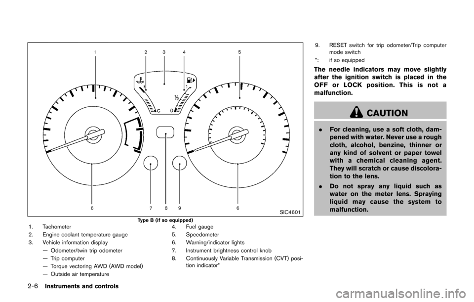
SIC4601
Type B (if so equipped)1. Tachometer (P.2-9)
2. Engine coolant temperature gauge (P.2-10)
3. Vehicle information display (P.2-11)— Odometer/twin trip odometer (P.2-7)
— Trip computer (P.2-13)
— Torque vectoring AWD (AWD model)
(P.2-14) — Outside air temperature (P.2-12)
4. Fuel gauge (P.2-11)
5. Speedometer (P.2-7)
6. Warning/indicator lights (P.2-15)
7. Instrument brightness control knob (P.2-43)
8. Continuously Variable Transmission (CVT) posi- tion indicator* (P.2-12) 9. RESET switch for trip odometer (P.2-7)/Trip
computer mode switch (P.2-13)
*: if so equipped
Page 20 of 416

JVC0747X
MR16DDT ENGINE
1. Engine oil filler cap (P.8-5)
2. Radiator filler cap (P.8-5)— Vehicle overheat (P.6-11)
3. Brake and clutch* fluid reservoir (P.8-9)
4. Air cleaner (P.8-14)
5. Window washer fluid reservoir (P.8-9) 6. Engine drive belt location (P.8-12)
7. Engine oil dipstick (P.8-5)
8. Engine coolant reservoir (P.8-5)
9. Fuse/fusible link holder (P.8-17)
10. Battery (P.8-10)
— Jump starting (P.6-9)
*: for Manual Transmission (MT) models
Illustrated table of contents0-11
ENGINE COMPARTMENT
Page 80 of 416

2 Instruments and controls
Cockpit ........................................................................\
................ 2-3
Instrument panel ........................................................................\
2-4
Meters and gauges ................................................................... 2-5Speedometer and odometer ............................................ 2-7
Tachometer ........................................................................\
... 2-9
Engine coolant temperature gauge (Type B) (if
so equipped) ..................................................................... 2-10
Fuel gauge ........................................................................\
. 2-11
Vehicle information display (Type A) (if
so equipped) ..................................................................... 2-11
Vehicle information display (Type B) (if
so equipped) ..................................................................... 2-12
Outside air temperature .................................................. 2-12
Continuously Variable Transmission (CVT) position
indicator (if so equipped) ............................................... 2-12
Trip computer .................................................................... 2-13
Warning lights, indicator lights and
audible reminders ................................................................... 2-15 Checking lights ................................................................. 2-16
Warning lights ................................................................... 2-16
Indicator lights ................................................................... 2-21
Audible reminders ............................................................ 2-23
Integrated control system (if so equipped) ..................... 2-24
Drive mode ........................................................................\
. 2-24
Setup function ................................................................... 2-25 Drive information ............................................................ 2-30
Eco information ............................................................... 2-31
Security systems ................................................................... 2-33
Vehicle Security System ............................................... 2-33
NISSAN Vehicle Immobilizer System ........................ 2-34
Wiper and washer switch ................................................... 2-36
Rear window wiper and washer switch .......................... 2-37
Rear window and outside mirror defroster switch ....... 2-38
Headlight and turn signal switch ....................................... 2-39 Xenon headlights (if so equipped) ............................ 2-39
Headlight switch ............................................................ 2-40
Turn signal switch .......................................................... 2-43
Fog light switch (if so equipped) .............................. 2-44
Horn ........................................................................\
.................. 2-44
Vehicle Dynamic Control (VDC) off switch .................... 2-44
Heated seats (if so equipped) ........................................... 2-45
Power outlet ........................................................................\
.... 2-46
Storage ........................................................................\
............ 2-47 Cup holders ..................................................................... 2-47
Cargo floor box ............................................................... 2-48
Glove box ........................................................................\
. 2-48
Coat hook ........................................................................\
2-48
Cargo cover (if so equipped) ..................................... 2-49
Windows ........................................................................\
......... 2-50 Power windows .............................................................. 2-50
Page 85 of 416

2-6Instruments and controls
SIC4601
Type B (if so equipped)1. Tachometer
2. Engine coolant temperature gauge
3. Vehicle information display— Odometer/twin trip odometer
— Trip computer
— Torque vectoring AWD (AWD model)
— Outside air temperature 4. Fuel gauge
5. Speedometer
6. Warning/indicator lights
7. Instrument brightness control knob
8. Continuously Variable Transmission (CVT) posi-
tion indicator* 9. RESET switch for trip odometer/Trip computer
mode switch
*: if so equipped
The needle indicators may move slightly
after the ignition switch is placed in the
OFF or LOCK position. This is not a
malfunction.
CAUTION
. For cleaning, use a soft cloth, dam-
pened with water. Never use a rough
cloth, alcohol, benzine, thinner or
any kind of solvent or paper towel
with a chemical cleaning agent.
They will scratch or cause discolora-
tion to the lens.
. Do not spray any liquid such as
water on the meter lens. Spraying
liquid may cause the system to
malfunction.
Page 89 of 416

2-10Instruments and controls
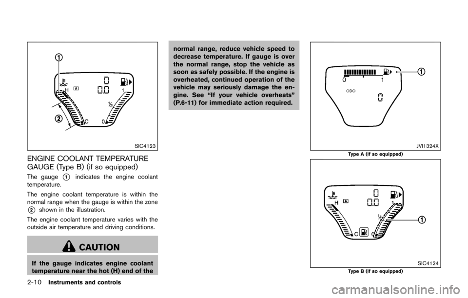
SIC4123
ENGINE COOLANT TEMPERATURE
GAUGE (Type B) (if so equipped)
The gauge*1indicates the engine coolant
temperature.
The engine coolant temperature is within the
normal range when the gauge is within the zone
*2shown in the illustration.
The engine coolant temperature varies with the
outside air temperature and driving conditions.
CAUTION
If the gauge indicates engine coolant
temperature near the hot (H) end of the normal range, reduce vehicle speed to
decrease temperature. If gauge is over
the normal range, stop the vehicle as
soon as safely possible. If the engine is
overheated, continued operation of the
vehicle may seriously damage the en-
gine. See “If your vehicle overheats”
(P.6-11) for immediate action required.
JVI1324X
Type A (if so equipped)
SIC4124Type B (if so equipped)
Page 97 of 416

2-18Instruments and controls
CAUTION
Running the engine with the engine oil
pressure warning light on could cause
serious damage to the engine almost
immediately. Such damage is not cov-
ered by warranty. Turn off the engine as
soon as it is safe to do so.
High temperature warning light (if
so equipped)
When the ignition switch is in the ON position,
the high temperature warning light illuminates
and then turns off. This indicates that the high
temperature sensor in the engine coolant system
is operational.
CAUTION
. If the high temperature warning
light illuminates while the engine
is running, it may indicate the en-
gine temperature is extremely high.
Stop the vehicle safely as soon as
possible. If the vehicle is over-
heated, continuing vehicle opera-
tion may seriously damage the engine. (For the immediate action
required, see “If your vehicle over-
heats” (P.6-11) .)
Intelligent Key system warning light
After the ignition switch is placed in the ON
position, this light comes on for about 2 seconds
and then turns off.
This light illuminates or blinks as follows:
.
The light blinks in yellow when the door is
closed with the Intelligent Key left outside
the vehicle and the ignition switch in the
ACC or ON position. Make sure that the
Intelligent Key is inside the vehicle.
. The light blinks in green when the Intelligent
Key battery is running out of power. Replace
the battery with a new one. (See “Intelligent
Key battery replacement” (P.8-20) .)
. The light illuminates in yellow when it warns
of a malfunction with Intelligent Key system.
If the warning light illuminates in yellow while the
engine is stopped, it may be impossible to start
the engine. If the light comes on while the engine
is running, you can drive the vehicle. However in
these cases, it is recommended you visit a
NISSAN dealer for repair as soon as possible.
Low fuel warning light
This light illuminates when the fuel in the tank is
getting low. Refuel as soon as it is convenient,
preferably before the fuel gauge reaches the 0
(empty) position.
There will be a small reserve of fuel
remaining in the tank when the fuel gauge
reaches the 0 position.
Low tire pressure warning light
Your vehicle is equipped with a Tire Pressure
Monitoring System (TPMS) that monitors the tire
pressure of all tires except the spare.
The low tire pressure warning light warns of low
tire pressure or indicates that the TPMS is not
functioning properly.
After the ignition switch is placed in the ON
position, this light illuminates for about 1 second
and turns off.
Low tire pressure warning:
If the vehicle is being driven with low tire
pressure, the warning light will illuminate. A
CHECK TIRE PRES (pressure) warning mes-
sage is also displayed in the vehicle information
display.
When the low tire pressure warning light
illuminates, you should stop and adjust the tire
Page 194 of 416

OPERATING TIPS (for automatic air
conditioner)
.When the engine coolant temperature and
outside air temperature are low, the air flow
from the foot outlets may not operate. This is
not a malfunction. After the coolant tem-
perature warms up, air will flow normally
from the foot outlets.
. The automatic air conditioner is equipped
with sensors as illustrated. The sensors
*A
and*Bon the instrument panel help
maintain a constant temperature. Do not
put anything on or around these sensors.
IN-CABIN MICROFILTER
The air conditioning system is equipped with an
in-cabin microfilter which collects dirt, pollen,
dust, etc. To make sure the air conditioner heats,
defogs, and ventilates efficiently, replace the
filter in accordance with the specified main-
tenance intervals listed in the “9. Maintenance
and schedules” section. It is recommended to
see a NISSAN dealer to replace the filter.
The filter should be replaced if the air flow
decreases significantly or if windows fog
up easily when operating the heater or air
conditioning system.
SERVICING AIR CONDITIONER
The air conditioner system in your vehicle is
charged with a refrigerant designed with the
environment in mind. This refrigerant will not
harm the earth’s ozone layer. Special char-
ging equipment and lubricant are required when
servicing your vehicle air conditioner. Using
improper refrigerants or lubricants will cause
severe damage to your air conditioner system.
(See “Capacities and recommended fluids/
lubricants” (P.10-2) for air conditioner system
refrigerant and lubricant recommendations.)
Your NISSAN dealer will be able to service your
environmentally friendly air conditioner system.
WARNING
The system contains refrigerant under
high pressure. To avoid personal injury,
any air conditioner service should be
done only by an experienced technician
with the proper equipment.
AUDIO OPERATION PRECAUTIONS
Radio
Place the ignition switch in the ACC or ON
position and push the FM·AM button to turn on
the radio. If you listen to the radio with the
engine not running, the ignition switch should be
placed in the ACC position.
Radio reception is affected by station signal
strength, distance from radio transmitter, build-
ings, bridges, mountains and other external
influences. Intermittent changes in reception
quality normally are caused by these external
influences.
Using a cellular phone in or near the
vehicle may influence radio reception
quality.
Radio reception:
Your vehicle radio system is equipped with
state-of-the-art electronic circuits to enhance
radio reception. These circuits are designed to
extend reception range, and to enhance the
quality of that reception.
However there are some general characteristics
of both FM and AM radio signals that can affect
radio reception quality in a moving vehicle, even
when the finest equipment is used. These
characteristics are completely normal in a given
reception area, and do not indicate any mal-
Heater, air conditioner, audio and phone systems4-35
AUDIO SYSTEM
Page 262 of 416

5 Starting and driving
Precautions when starting and driving ................................ 5-2Exhaust gas (carbon monoxide) ...................................... 5-2
Three-way catalyst .............................................................. 5-3
Tire Pressure Monitoring System (TPMS) .................... 5-3
Avoiding collision and rollover ......................................... 5-6
Off-road recovery ................................................................ 5-6
Rapid air pressure loss ...................................................... 5-6
Drinking alcohol/drugs and driving ................................. 5-7
Driving safety precautions ................................................. 5-7
Push-button ignition switch .................................................... 5-9
Operating range for engine start function ................. 5-10
Push-button ignition switch operation ........................ 5-10
Push-button ignition switch positions ......................... 5-11
Emergency engine shut off ............................................ 5-11
Intelligent Key battery discharge .................................. 5-12
Before starting the engine ................................................... 5-12
Starting the engine ................................................................ 5-13
Driving the vehicle ................................................................. 5-14 Continuously Variable Transmission (CVT) ................ 5-14
Manual Transmission (MT) ............................................. 5-19
Integrated control system (if so equipped) ..................... 5-21 Drive mode ........................................................................\
. 5-22
Parking brake ........................................................................\
.. 5-25
Cruise control ........................................................................\
. 5-26 Precautions on cruise control ....................................... 5-26 Cruise control operations ............................................ 5-26
Break-in schedule ................................................................. 5-27
Fuel Efficient Driving Tips ................................................... 5-28
Increasing fuel economy ...................................................... 5-29
All-Wheel Drive (AWD) (if so equipped) ........................ 5-29 All-Wheel Drive (AWD) mode
switch operations ........................................................... 5-29
AWD warning light ........................................................ 5-31
Parking/parking on hills ........................................................ 5-33
Electric power steering ........................................................ 5-34
Brake system ........................................................................\
.. 5-35 Braking precautions ...................................................... 5-35
Brake assist ........................................................................\
.... 5-36
Brake assist ..................................................................... 5-36
Anti-lock Braking System (ABS) ............................... 5-36
Vehicle Dynamic Control (VDC) system ......................... 5-37
Cold weather driving ............................................................ 5-39 Freeing a frozen door lock ........................................... 5-39
Anti-freeze ........................................................................\
5-39
Battery ........................................................................\
....... 5-39
Draining of coolant water ............................................. 5-39
Tire equipment ................................................................ 5-39
Special winter equipment ............................................ 5-39
Driving on snow or ice ................................................. 5-39
Engine block heater (if so equipped) ....................... 5-40