Page 102 of 248

5. Information
— The TCU (Telematics Control Unit)or other systems of your vehicle
are not working properly.
— It may not be possible to make an emergency call depending on the
severity of a collision and/or emer-
gency.
. Park the vehicle in a safe location
and set the parking brake before
operating .
. Only use this service in case of an
emergency. There may be a penalty
for inappropriate use of the service.
. Radio waves could adversely affect
electric medical equipment. Indivi-
duals who use a pacemaker should
contact the device manufacturer re-
garding any possible effects before
using the system.
. The TCU (Telematics Control Unit)
antenna is installed inside the upper
central part of the instrument panel.
An occupant should not get any
closer to the antenna than specified
by the pacemaker manufacturer. The
radio waves from the TCU antenna
may adversely affect the operation of
the pacemaker while using the Nis- sanConnectSMServices.
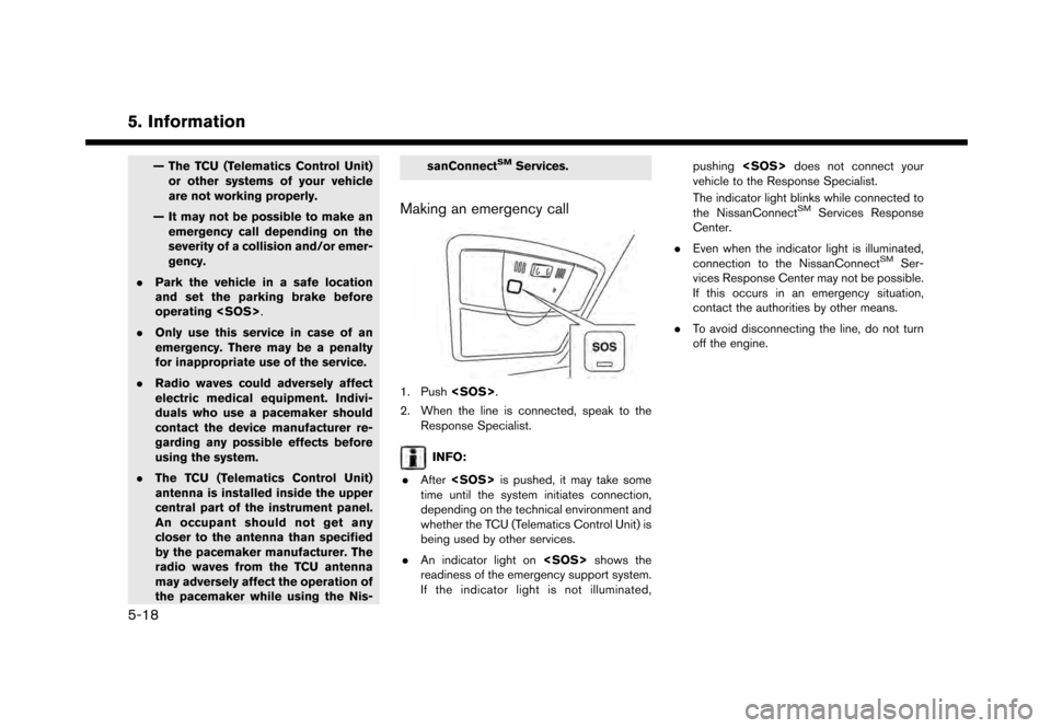
Making an emergency call
1. Push
.
2. When the line is connected, speak to the Response Specialist.
INFO:
. After is pushed, it may take some
time until the system initiates connection,
depending on the technical environment and
whether the TCU (Telematics Control Unit) is
being used by other services.
. An indicator light on shows the
readiness of the emergency support system.
If the indicator light is not illuminated, pushing
does not connect your
vehicle to the Response Specialist.
The indicator light blinks while connected to
the NissanConnect
SMServices Response
Center.
. Even when the indicator light is illuminated,
connection to the NissanConnect
SMSer-
vices Response Center may not be possible.
If this occurs in an emergency situation,
contact the authorities by other means.
. To avoid disconnecting the line, do not turn
off the engine.
5-18
Page 116 of 248
![NISSAN GT-R 2017 R35 Multi Function Display Owners Manual 6. Navigation
The following settings are available.
Menu itemAction
[Change View] [2D Map] Display 2D map.
[Split: 2D Map] Display 2D map on both left and right side of the split screen.
[Birdview (3D NISSAN GT-R 2017 R35 Multi Function Display Owners Manual 6. Navigation
The following settings are available.
Menu itemAction
[Change View] [2D Map] Display 2D map.
[Split: 2D Map] Display 2D map on both left and right side of the split screen.
[Birdview (3D](/manual-img/5/524/w960_524-115.png)
6. Navigation
The following settings are available.
Menu itemAction
[Change View] [2D Map] Display 2D map.
[Split: 2D Map] Display 2D map on both left and right side of the split screen.
[Birdview (3D)] Display 3D map.
[Split: Birdview Map] Display 2D map on the left side and 3D map on the right side of the screen.
[View Settings] [Intersection] Display the enlarged view of intersection on the left side of the screen during
route guidance.
“Route guidance screens” (page 6-31)
[Turn List] Display the turn list on the left screen when a route is set.
“Route guidance screens” (page 6-31)
[Drive Report] Display your ECO driving performance score on the left side of the screen.
Touch [Log] to view the Drive Report history. Touch [Reset] to clear the past
records.
Push
Page 117 of 248
![NISSAN GT-R 2017 R35 Multi Function Display Owners Manual Menu itemAction
[Medium]
[Small]
[Birdview Angle] Adjusts the Birdview
TMangle using the adjust bar displayed on the left side of
the screen. [Birdview Angle] is available only when 3D map is displaye NISSAN GT-R 2017 R35 Multi Function Display Owners Manual Menu itemAction
[Medium]
[Small]
[Birdview Angle] Adjusts the Birdview
TMangle using the adjust bar displayed on the left side of
the screen. [Birdview Angle] is available only when 3D map is displaye](/manual-img/5/524/w960_524-116.png)
Menu itemAction
[Medium]
[Small]
[Birdview Angle] Adjusts the Birdview
TMangle using the adjust bar displayed on the left side of
the screen. [Birdview Angle] is available only when 3D map is displayed.
[North Up when Zoomed Out] When this setting is ON, the orientation of the map is automatically changed
to North Up when the widest map scale is selected.
[Select Text to Display on
Map] [Place Names]
Allows place names to be displayed on the map screen.
[Facility Names] Allows facilities names to be displayed on the map screen.
[Road Names] Allows road names to be displayed on the map screen.
[Left Split Map Settings] [Map Orientation] The map orientation for the left side of split screen can be selected from
North Up or Heading Up.
[Long Range] Long Range Map View is available only when the left side of split screen is in
Heading Up mode.
With this item turned on, the vehicle position icon on the left screen will be
located slightly lower than the center of the screen so that a wider area in the
traveling direction can be viewed.
[Map Scale] Allows to change the scale of the map displayed on the left side of the split
screen.
[Show all Freeway Exits on Route] Turns on/off the freeway exit information display.
[Auto. Show Turn List on Freeway] The turn list can be set to on or off to be displayed automatically while driving
on a freeway.
[Back to Map] Back to the current location map.
6. Navigation
6-11
Page 173 of 248

Data provided to you hereunder.
Government End Users.If the Data is being
acquired by or on behalf of the United States
government or any other entity seeking or
applying rights similar to those customarily
claimed by the United States government, the
Data is a “commercial item” as that term is
defined at 48 C.F.R. (“FAR”) 2.101, is licensed in
accordance with the End-User Terms under
which this Data was provided, and each copy
of the Data delivered or otherwise furnished shall
be marked and embedded as appropriate with
the following “Notice of Use,” and shall be
treated in accordance with such Notice:
NOTICE OF USE
CONTRACTOR (MANUFACTURER/ SUPPLIER) NAME: HERE
CONTRACTOR (MANUFACTURER/SUPPLIER) ADDRESS:
c/o Nokia 425 West Randolph Street, Chicago, Illinois 60606
This Data is a commercial item as defined in FAR
2.101 and is subject to the End-User Terms under which this Data was provided.
*
C2012 HERE – All rights reserved.
If the Contracting Officer, federal government
agency, or any federal official refuses to use the legend provided herein, the Contracting Officer,
federal government agency, or any federal official
must notify HERE prior to seeking additional or
alternative rights in the Data
HOW TO HANDLE THE SD CARD
When handling the SD card, please be careful
and adhere to the following instructions:
. Always follow the instructions described in
this manual and in the handbook attached to
the SD card when using an SD card in this
device.
. Do not handle an SD card with wet hands.
Doing so may cause electric shock or a
malfunction.
. Do not allow hands or metal objects to
contact the terminal area of SD cards.
. Do not place SD cards on the instrument
panel, on any place with direct sunlight or in
moist circumstances. Doing so may damage
or deform the SD card.
. Do not use any conventional cleaner, ben-
zine, thinner or antistatic spray.
. Do not use SD cards in any place where
static electricity or electric noise adversely
affects SD cards. This may cause data
corruption or data loss. .
SD card optimization must not be performed.
. Always place the SD card in its storage case
when not in use.
. If an SD card is disposed of when it is not
used, it is recommended not only to delete
the stored data but also to physically break
the card.
6. Navigation
6-67
Page 192 of 248
7. Voice recognition
VOICE RECOGNITION SETTINGS
The voice recognition settings can be changed.
1. Touch [Setting] on the Launch Bar.
2. Touch [Voice Recognition].
3. Touch the item you would like to set.
Available settings. [Minimize Voice Feedback]:
Turns the minimize voice feedback function
on/off. When this item is turned on, short and
minimized voice feedback will be provided.
. [Audio device setting]:
Select an audio device to be operated via the
voice recognition system from the audio
devices connected to the USB ports. A
device with an indicator light illuminated can
be operated with the voice recognition
system.
7-18
Page 202 of 248
8. Multi function meter
NOTICE
Do not rely on the range reading alone.
Even when traveling a distance for which
there is a sufficient amount of fuel, refuel
when the fuel gauge approaches empty
or when the low fuel warning light
illuminates.
Fuel flow
Displays the amount of fuel injected into the
engine by the fuel injector.
Recent fuel economy
In the large panel, this meter displays the timeline
of fuel consumption for each minute over the past
twenty minutes. In the small panel, this meter
displays fuel consumption readings over the past
twenty seconds.
INFO:
. The small panel will display “-.-”:
— when the vehicle is stopped
— for the first few moments of driving
. The large panel will not display a graph while
the vehicle is stopped.
8-10
Page 219 of 248

SYSTEM UNIT
LIQUID CRYSTAL DISPLAY
Symptom Possible cause Possible solution
The screen is too dark. The cabin temperature is too low.Wait until the cabin temperature becomes moderate.
Screen brightness is set to the maximum darkness. Adjust the brightness setting of the screen.
“Display settings” (page 2-18)
The screen is too bright. Screen brightness is set to the maximum brightness. Adjust the brightness setting of the screen.
“Display settings” (page 2-18)
A small black spot or a small bright spot appears on
the screen. This is a typical phenomenon for liquid crystal
displays.This is not a malfunction.
A dot or stripe pattern appears on the screen. Electromagnetic waves that are generated from neon billboards, high voltage electric power cables, ham
radios or other radio devices equipped to other
vehicles may adversely affect the screen.This is not a malfunction.
Image lag appears on the screen. This is a typical phenomenon for liquid crystal
displays.This is not a malfunction.
Image motion displayed on the screen is slow. The cabin temperature is less than 508F (108C). Wait until the cabin temperature rises to within 508F (108C) and 1228F (508C).
When looking at the screen from an angle, the screen
lightens or darkens. This is a typical phenomenon for liquid crystal
displays.Adjust the brightness setting of the screen.
“Display settings” (page 2-18)
9. Troubleshooting guide
9-3
Page 222 of 248
9. Troubleshooting guide
Functional
SymptomPossible cause Possible solution
Keep losing my local stations. The digital coverage is slightly less than the analog
signal coverage.Verify correct operation on another station. This is
expected behavior.
Shadowing (urban/terrain) can cause reduced digital
coverage. Verify correct operation on another station.
Some data fields are blank. Text information is sent at the broadcaster’s discre-
tion.Verify correct operation on another station. Report
station issues.
Text information is truncated / appears to be more
available. The display is limited to a fixed number of characters
and more data is being sent than can be shown.This is an intended behavior.
AM reception changes at night. AM stations are required by the government (FCC) to
lower their power at night.This is not a malfunction.
9-6