2017 NISSAN FRONTIER ECU
[x] Cancel search: ECUPage 443 of 478
●Do not load your vehicle any heavier
than the GVWR or the maximum front
and rear GAWRs. If you do, parts of your
vehicle can break, tire damage could
occur, or it can change the way your
vehicle handles. This could result in loss
of control and cause personal injury.
UTILI-TRACK™ CHANNEL SYSTEM
(if so equipped)
1. Side channels
2. Header channel
3. Header channel
WARNING
●Properly install and tighten the tie-
down cleats into the Utili-track™ chan-
nel system. Also, do not attach any rope
or straps directly to the channel. Failure
to properly install the tie-down cleats or
attaching ropes or straps directly to the
channel can cause the cargo to become
unsecured. In a sudden stop or colli-
sion, unsecured cargo could cause per-
sonal injury.
● Properly secure all cargo with ropes or
straps to help prevent it from sliding or
shifting. In a sudden stop or collision,
unsecured cargo could cause personal
injury.
The Utili-track™ channel system allows you to
move tie-down clamps in the bed to the best
location to secure a load.
The tie-down cleats must be installed so the
clamp is properly seated in the notches in the rail.
If the tie-down cleat is not seated in the notches,
it will not be flush with the rail and cannot be
properly tightened. The bolt in the center of the
cleat must be tightened hand tight (20 – 40 in-
lbs)
LTI2082
10-20Technical and consumer information
Page 447 of 478
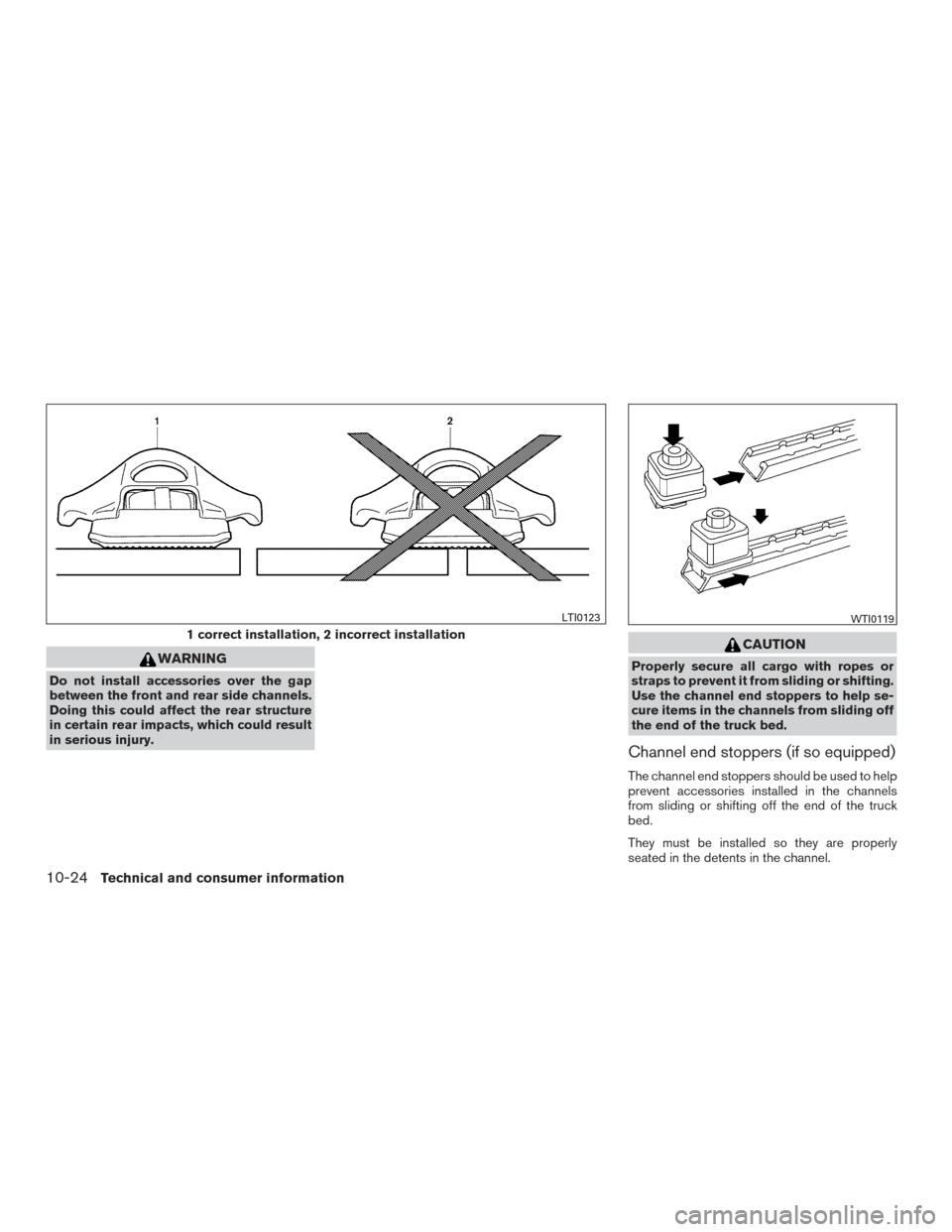
WARNING
Do not install accessories over the gap
between the front and rear side channels.
Doing this could affect the rear structure
in certain rear impacts, which could result
in serious injury.
CAUTION
Properly secure all cargo with ropes or
straps to prevent it from sliding or shifting.
Use the channel end stoppers to help se-
cure items in the channels from sliding off
the end of the truck bed.
Channel end stoppers (if so equipped)
The channel end stoppers should be used to help
prevent accessories installed in the channels
from sliding or shifting off the end of the truck
bed.
They must be installed so they are properly
seated in the detents in the channel.
1 correct installation, 2 incorrect installation
LTI0123WTI0119
10-24Technical and consumer information
Page 448 of 478
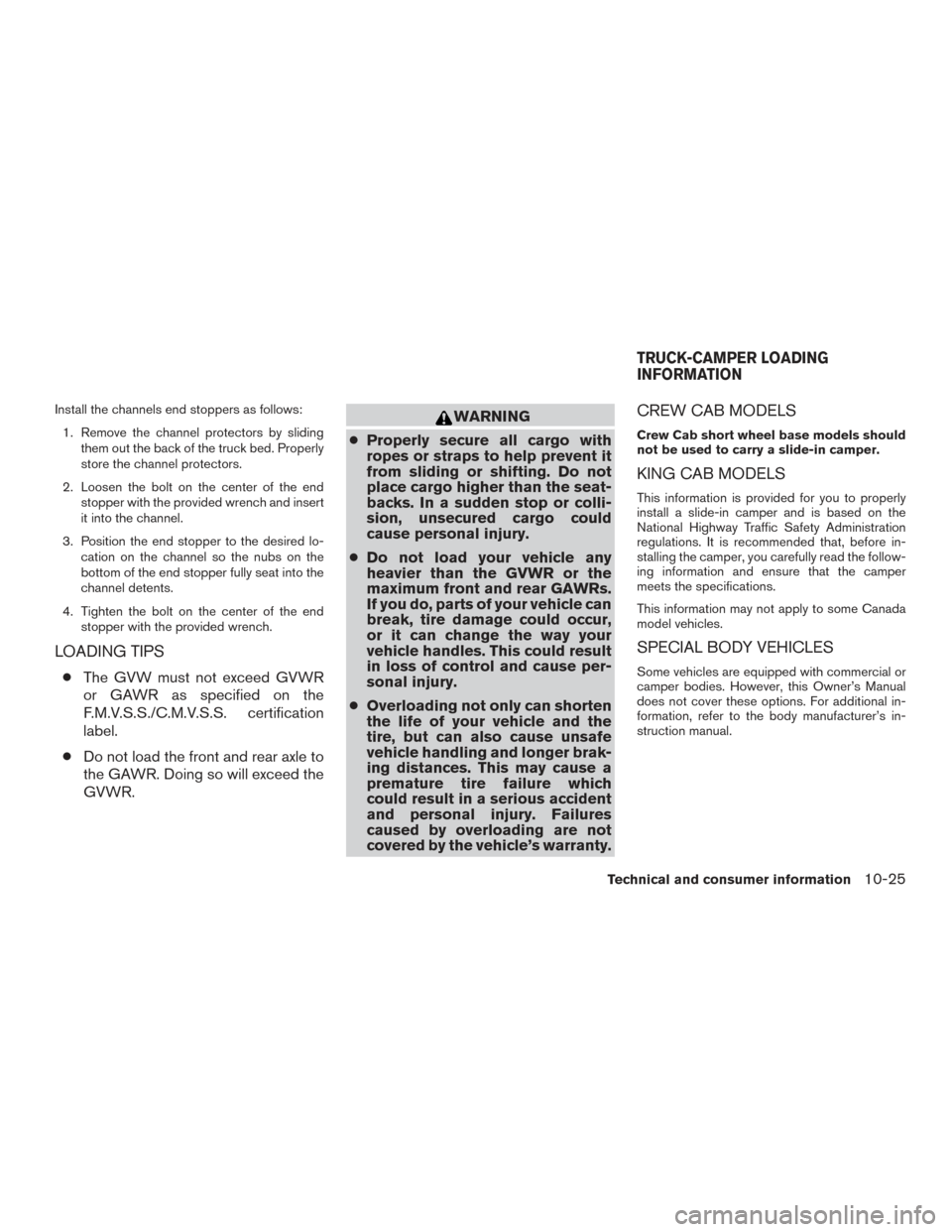
Install the channels end stoppers as follows:1. Remove the channel protectors by sliding them out the back of the truck bed. Properly
store the channel protectors.
2. Loosen the bolt on the center of the end stopper with the provided wrench and insert
it into the channel.
3. Position the end stopper to the desired lo- cation on the channel so the nubs on the
bottom of the end stopper fully seat into the
channel detents.
4. Tighten the bolt on the center of the end stopper with the provided wrench.
LOADING TIPS
●The GVW must not exceed GVWR
or GAWR as specified on the
F.M.V.S.S./C.M.V.S.S. certification
label.
● Do not load the front and rear axle to
the GAWR. Doing so will exceed the
GVWR.
WARNING
● Properly secure all cargo with
ropes or straps to help prevent it
from sliding or shifting. Do not
place cargo higher than the seat-
backs. In a sudden stop or colli-
sion, unsecured cargo could
cause personal injury.
● Do not load your vehicle any
heavier than the GVWR or the
maximum front and rear GAWRs.
If you do, parts of your vehicle can
break, tire damage could occur,
or it can change the way your
vehicle handles. This could result
in loss of control and cause per-
sonal injury.
● Overloading not only can shorten
the life of your vehicle and the
tire, but can also cause unsafe
vehicle handling and longer brak-
ing distances. This may cause a
premature tire failure which
could result in a serious accident
and personal injury. Failures
caused by overloading are not
covered by the vehicle’s warranty.CREW CAB MODELS
Crew Cab short wheel base models should
not be used to carry a slide-in camper.
KING CAB MODELS
This information is provided for you to properly
install a slide-in camper and is based on the
National Highway Traffic Safety Administration
regulations. It is recommended that, before in-
stalling the camper, you carefully read the follow-
ing information and ensure that the camper
meets the specifications.
This information may not apply to some Canada
model vehicles.
SPECIAL BODY VEHICLES
Some vehicles are equipped with commercial or
camper bodies. However, this Owner’s Manual
does not cover these options. For additional in-
formation, refer to the body manufacturer’s in-
struction manual.
TRUCK-CAMPER LOADING
INFORMATION
Technical and consumer information10-25
Page 449 of 478
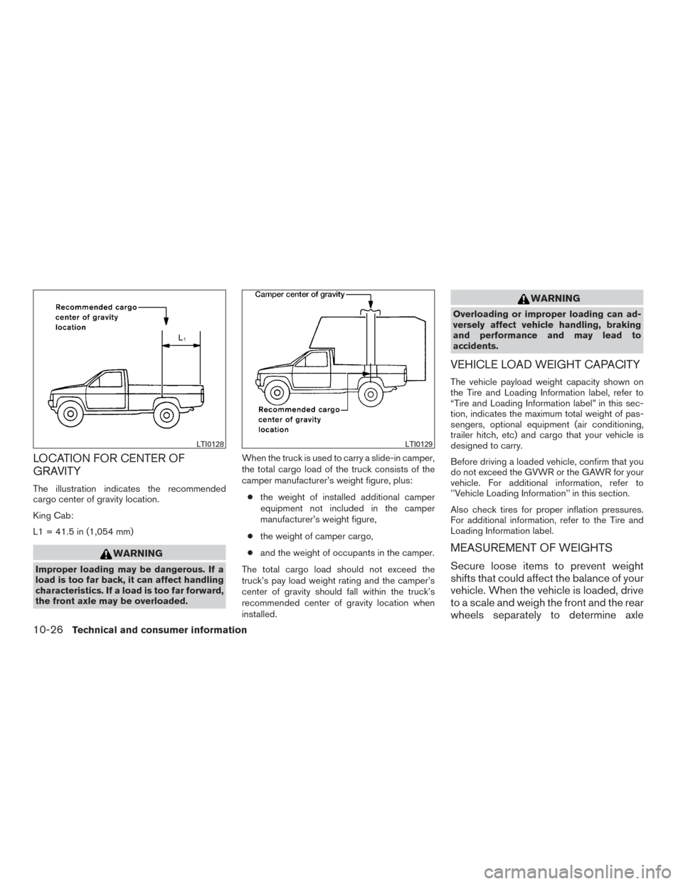
LOCATION FOR CENTER OF
GRAVITY
The illustration indicates the recommended
cargo center of gravity location.
King Cab:
L1 = 41.5 in (1,054 mm)
WARNING
Improper loading may be dangerous. If a
load is too far back, it can affect handling
characteristics. If a load is too far forward,
the front axle may be overloaded.When the truck is used to carry a slide-in camper,
the total cargo load of the truck consists of the
camper manufacturer’s weight figure, plus:
● the weight of installed additional camper
equipment not included in the camper
manufacturer’s weight figure,
● the weight of camper cargo,
● and the weight of occupants in the camper.
The total cargo load should not exceed the
truck’s pay load weight rating and the camper’s
center of gravity should fall within the truck’s
recommended center of gravity location when
installed.
WARNING
Overloading or improper loading can ad-
versely affect vehicle handling, braking
and performance and may lead to
accidents.
VEHICLE LOAD WEIGHT CAPACITY
The vehicle payload weight capacity shown on
the Tire and Loading Information label, refer to
“Tire and Loading Information label” in this sec-
tion, indicates the maximum total weight of pas-
sengers, optional equipment (air conditioning,
trailer hitch, etc) and cargo that your vehicle is
designed to carry.
Before driving a loaded vehicle, confirm that you
do not exceed the GVWR or the GAWR for your
vehicle. For additional information, refer to
’’Vehicle Loading Information’’ in this section.
Also check tires for proper inflation pressures.
For additional information, refer to the Tire and
Loading Information label.
MEASUREMENT OF WEIGHTS
Secure loose items to prevent weight
shifts that could affect the balance of your
vehicle. When the vehicle is loaded, drive
to a scale and weigh the front and the rear
wheels separately to determine axle
LTI0128LTI0129
10-26Technical and consumer information
Page 455 of 478
TOWING SAFETY
Trailer hitch
Your vehicle may be equipped with an optional
trailer tow package. The trailer tow package in-
cludes a receiver-type frame mounted hitch. This
hitch is rated for the maximum towing capacity of
this vehicle when the proper towing equipment is
used. Choose a proper ball mount and hitch ball
that is rated for the trailer to be towed. Genuine
NISSAN ball mounts and hitch balls are available
from a NISSAN dealer.
If your vehicle is not equipped with the optional
trailer tow package, check the towing capacity of
your bumper hitch or receiver-type frame
mounted hitch. Choose a proper hitch for your
vehicle and trailer. A Genuine NISSAN trailer
hitch is available from a NISSAN dealer. Make
sure the trailer hitch is securely attached to the
vehicle to help avoid personal injury or property
damage due to sway caused by crosswinds,
rough road surfaces or passing trucks.
WARNING
Trailer hitch components have specific
weight ratings. Your vehicle may be ca-
pable of towing a trailer heavier than the
weight rating of the hitch components.
Never exceed the weight rating of the
hitch components. Doing so can cause
serious personal injury or property
damage.
Hitch ball
Choose a hitch ball of the proper size and weight
rating for your trailer:● The required hitch ball size is stamped on
most trailer couplers. Most hitch balls also
have the size printed on the top of the ball.
● Choose the proper class hitch ball based on
the trailer weight.
● The diameter of the threaded shank of the
hitch ball must be matched to the ball mount
hole diameter. The hitch ball shank should
be no more than 1/16” smaller than the hole
in the ball mount. ●
The threaded shank of the hitch ball must be
long enough to be properly secured to the
ball mount. There should be at least 2
threads showing beyond the lock washer
and nut.
Ball mount
The hitch ball is attached to the ball mount and
the ball mount is inserted into the hitch receiver.
Choose a proper class ball mount based on the
trailer weight. Additionally, the ball mount should
be chosen to keep the trailer tongue level with the
ground.
10-32Technical and consumer information
Page 457 of 478
Sway control device
Sudden maneuvers, wind gusts, and buffeting
caused by other vehicles can affect trailer han-
dling. Sway control devices may be used to help
control these affects. If you choose to use one,
contact a reputable trailer hitch supplier to make
sure the sway control device will work with the
vehicle, hitch, trailer and the trailer’s brake sys-
tem. Follow the instructions provided by the
manufacturer for installing and using the sway
control device.
Class I hitch
Class I trailer hitch equipment (receiver, ball
mount and hitch ball) can be used to tow trailers
of a maximum weight of 2,000 lb (907 kg) .
Class II hitch
Class II trailer hitch equipment (receiver, ball
mount and hitch ball) can be used to tow trailers
of a maximum weight of 3,500 lb (1,587 kg).
The Genuine NISSAN step bumper is consid-
ered a Class II ball mount.
Class III hitch
Class III trailer hitch equipment (receiver, ball
mount and hitch ball) can be used to tow trailers
of a maximum weight of 5,000 lb (2,268 kg).
Class IV hitch
Class IV trailer hitch equipment (receiver, ball
mount and hitch ball) can be used to tow trailers
of a maximum weight of 10,000 lb (4,535 kg). A
weight distributing hitch should be used to tow
trailers that weigh over 5,000 lb (2,268 kg).
Your vehicle may be equipped with Class IV
trailer hitch equipment that has a 10,000 lb
(4,535 kg) maximum weight rating, but your ve-
hicle is only capable of towing the maximum
trailer weights shown in the “Towing
Load/Specification” chart in this section.
CAUTION
●Special hitches which include frame re-
inforcements are required for towing
above 2,000 lb (907 kg) . Suitable Genu-
ine NISSAN hitches, ball mounts and
hitch balls for pickup trucks and sport
utility vehicles are available at a
NISSAN dealer.
● The hitch should not be attached to or
affect the operation of the impact-
absorbing bumper.
● Do not use axle-mounted hitches. ●
Do not modify the vehicle exhaust sys-
tem, brake system, etc. to install a
trailer hitch.
● To reduce the possibility of additional
damage if your vehicle is struck from
the rear, where practical, remove the
receiver when not in use.
● Regularly check that all trailer hitch
mounting bolts are securely mounted.
Tire pressures
● When towing a trailer, inflate the ve-
hicle tires to the recommended cold
tire pressure indicated on the Tire
and Loading Information label.
● Trailer tire condition, size, load rating
and proper inflation pressure should
be in accordance with the trailer and
tire manufacturer’s specifications.
Safety chains
Always use suitable safety chains between your
vehicle and the trailer. The safety chains should
be crossed and should be attached to the hitch,
not to the vehicle bumper or axle. The safety
chains can be attached to the bumper if the hitch
10-34Technical and consumer information
Page 459 of 478
Pre-towing tips
●Be certain your vehicle maintains a level
position when a loaded and/or unloaded
trailer is hitched. Do not drive the vehicle if it
has an abnormal nose-up or nose-down
condition; check for improper tongue load,
overload, worn suspension or other possible
causes of either condition.
● Always secure items in the trailer to prevent
load shift while driving.
●
Keep the cargo load as low as possible in the
trailer to keep the trailer center of gravity low.
● Load the trailer so approximately 60% of the
trailer load is in the front half and 40% is in
the back half. Also make sure the load is
balanced side to side.
● Check your hitch, trailer tire pressure, ve-
hicle tire pressure, trailer light operation, and
trailer wheel lug nuts every time you attach a
trailer to the vehicle.
● Be certain your rearview mirrors conform to
all federal, state or local regulations. If not,
install any mirrors required for towing before
driving the vehicle.
●
Determine the overall height of the vehicle and
trailer so the required clearance is known.
Trailer towing tips
In order to gain skill and an understanding of the
vehicle’s behavior, you should practice turning,
stopping and backing up in an area which is free
from traffic. Steering stability and braking perfor-
mance will be somewhat different than under
normal driving conditions.
● Always secure items in the trailer to prevent
load shift while driving.
● Lock the trailer hitch coupler with a pin or
lock to prevent the coupler from inadver-
tently becoming unlatched.
● Avoid abrupt starts, acceleration or stops.
● Avoid sharp turns or lane changes.
● Always drive your vehicle at a moderate
speed.
● When backing up, hold the bottom of the
steering wheel with one hand. Move your
hand in the direction in which you want the
trailer to go. Make small corrections and
back up slowly. If possible, have someone
guide you when you are backing up.
Always block the wheels on both vehicle and
trailer when parking. Parking on a slope is not
recommended; however, if you must do so:CAUTION
If you move the shift lever to the P (Park)
position before blocking the wheels and
applying the parking brake, transmission
damage could occur.
1. Apply and hold the brake pedal.
2. Have someone place blocks on the downhill side of the vehicle and trailer wheels.
3. After the wheel blocks are in place, slowly release the brake pedal until the blocks ab-
sorb the vehicle load.
4. Apply the parking brake.
5. Shift the transmission into P (Park) .
6. Make sure the
indicator light (if so
equipped) indicates the transfer case is in
4H, 4L, or 2H and that the ATP light is off. If
the
indicator light is flashing, or the
ATP light is ON, make sure the transmission
is in P (Park) (A/T) and turn the 4WD switch
to 2WD or 4H. For additional information,
refer to “Automatic transmission park warn-
ing light” in the “Instruments and controls”
section and “Using four wheel drive (4WD)”
in the “Starting and driving” section of this
manual.
7. Turn off the engine.
10-36Technical and consumer information
Page 464 of 478
You may notify NISSAN by contacting our
Consumer Affairs Department, toll-free, at
1-800-NISSAN-1.
For Canada
If you believe that your vehicle has a de-
fect which could cause a crash or could
cause injury or death, you should immedi-
ately inform Transport Canada in addition
to notifying NISSAN.
If Transport Canada receives complaints,
it may open an investigation, and if it finds
that a safety defect exists in a group of
vehicles, it may request that NISSAN con-
duct a recall campaign. However, Trans-
port Canada cannot become involved in
individual problems between you, your
dealer, or NISSAN.
You may contact Transport Canada’s De-
fect Investigations and Recalls Division
toll free at 1-800-333-0510. You may
also report safety defects online at:
https://wwwapps.tc.gc.ca/Saf-Sec-Sur/
7/PCDB-BDPP/fc-cp.aspx?lang=eng
(English speakers) orhttps://wwwapps.tc.gc.ca/Saf-Sec-Sur/
7/PCDB-BDPP/fc-cp.aspx?lang=fra
(French speakers)
Additional information concerning motor
vehicle safety may be obtained from Trans-
port Canada’s Road Safety Information
Centre at 1-800-333-0371 or online at
www.tc.gc.ca/roadsafety (English speak-
ers) or www.tc.gc.ca/securiteroutiere
(French speakers) .
To notify NISSAN of any safety concerns
please contact our Consumer Information
Centre toll free at 1-800-387-0122.
WARNING
A vehicle equipped with Four-Wheel Drive
(4WD) should never be tested using a two
wheel dynamometer (such as the dyna-
mometers used by some states for emis-
sions testing) , or similar equipment. Make
sure you inform the test facility personnel
that your vehicle is equipped with 4WD
before it is placed on a dynamometer.
Using the wrong test equipment may re-
sult in transmission damage or unex-
pected vehicle movement which could re-
sult in serious vehicle damage or personal
injury.
Due to legal requirements in some states and
Canadian Provinces, your vehicle may be re-
quired to be in what is called the “ready condi-
tion” for an Inspection/Maintenance (I/M) test of
the emission control system.
The vehicle is set to the “ready condition” when it
is driven through certain driving patterns. Usually,
the ready condition can be obtained by ordinary
usage of the vehicle.
READINESS FOR INSPECTION/
MAINTENANCE (I/M) TEST
Technical and consumer information10-41