Page 15 of 497
QR25DE engine
1. Power steering fluid reservoir (P. 8-11)
2. Engine coolant reservoir (P. 8-5)
3. Engine oil filler cap (P. 8-7)
4. Brake fluid reservoir (P. 8-12)
5. Air cleaner (P. 8-18)
6. Fuse/Fusible link box (P. 8-21)
7. Battery (P. 8-13)
8. Engine oil dipstick (P. 8-7)
9. Radiator cap (P. 8-5)
10. Drive belt location (P. 8-16)
11. Windshield-washer fluid reservoir(P. 8-12)
Refer to the page number indicated in pa-
rentheses for operating details.
LDI2111
ENGINE COMPARTMENT CHECK
LOCATIONS
0-8Illustrated table of contents
Page 16 of 497
VQ35DE engine
1. Power steering fluid reservoir (P. 8-11)
2. Engine coolant reservoir (P. 8-5)
3. Engine oil filler cap (P. 8-7)
4. Brake fluid reservoir (P. 8-12)
5. Air cleaner (P. 8-18)
6. Fuse/Fusible link box(P. 8-21)
7. Battery (P. 8-13)
8. Engine oil dipstick (P. 8-7)
9. Radiator cap (P. 8-5)
10. Drive belt location (P. 8-16)
11. Windshield-washer fluid reservoir(P. 8-12)
Refer to the page number indicated in pa-
rentheses for operating details.
LDI2112
Illustrated table of contents0-9
Page 79 of 497

2 Instruments and controls
Instrument panel...................................2-2
Meters and gauges ................................2-3
Speedometer and odometer .....................2-4
Tachometer ....................................2-5
Engine coolant temperature gauge ...............2-5
Fuel gauge ....................................2-6
Compass (if so equipped) ..........................2-7
Compass display ...............................2-7
Warning lights, indicator lights and audible
reminders ........................................ 2-10
Checking lights ............................... 2-10
Warning lights ................................ 2-11
Indicator lights ................................ 2-15
Audible reminders ............................. 2-17
Vehicle information display ......................... 2-17
How to use the vehicle information display .......2-18
Startup display ................................ 2-18
Resetting the trip computer .....................2-19
Settings ...................................... 2-19
Vehicle information display warnings and
indicators ..................................... 2-25
Security systems ................................. 2-29
Vehicle security system ......................... 2-29NISSAN Vehicle Immobilizer System
.............2-31
Wiper and washer switch ......................... 2-32
Switch operation .............................. 2-32
Rear window and outside mirror (if so equipped)
defroster switch .................................. 2-33
Headlight and turn signal switch ....................2-34
Headlight control switch ........................ 2-34
Daytime Running Light (DRL) system
(Type A) (if so equipped) .......................2-36
LED Daytime Running Light (DRL) system
(Type B) (if so equipped) .......................2-37
Instrument brightness control ...................2-37
Turn signal switch ............................. 2-38
Fog light switch (if so equipped) ................2-38
Horn ............................................ 2-39
Heated seat switches (if so equipped) ..............2-39
Heated steering wheel switch (if so equipped) .......2-40
V
ehicle Dynamic Control (VDC) off switch ...........2-41
E-call (SOS) switch (if so equipped) ................2-41
Power outlets .................................... 2-42
Extended storage switch .......................... 2-43
Storage ......................................... 2-44
Front-door pockets ............................ 2-44
Seatback pockets (if so equipped) ..............2-44
Page 82 of 497
17. Push-button ignition switch (P. 5-8)
18. Cruise control main/set switches(if so equipped) (P. 5-41)
Intelligent Cruise Control (ICC)
switches (if so equipped) (P. 5-41)
Bluetooth® Hands-free Phone System
(P. 4-27)
19. Tilt/telescopic steering wheel controls
(P. 3-35)
20. Vehicle information display controls
(P. 2-17)
Steering wheel switch for audio control
(P. 4-27)
21. Hood release (P. 3-30)
22. Trunk opener (P. 3-30) Vehicle Dynamic Control (VDC) OFF
switch (P. 2-41)
Heated steering wheel switch
(if so equipped) (P. 2-40)
*: Refer to the separate Navigation System Own-
er’s Manual (if so equipped) .
Refer to the page number indicated in pa-
rentheses for operating details.
1. Tachometer
2. Warning and indicator lights
3. Vehicle information displayOdometer
Twin trip odometer 4. Speedometer
5. Fuel gauge
6. Engine coolant temperature gauge
LIC3459
METERS AND GAUGES
Instruments and controls2-3
Page 84 of 497
Changing the display
Push the TRIP RESET
�2switch on the left side
of the instrument panel to change the display as
follows:
Trip
→ Trip→Odometer Mileage →
Trip
Resetting the trip odometer
Pushing the TRIP RESET switch
�2for more
than 1 second resets the currently displayed trip
odometer to zero.
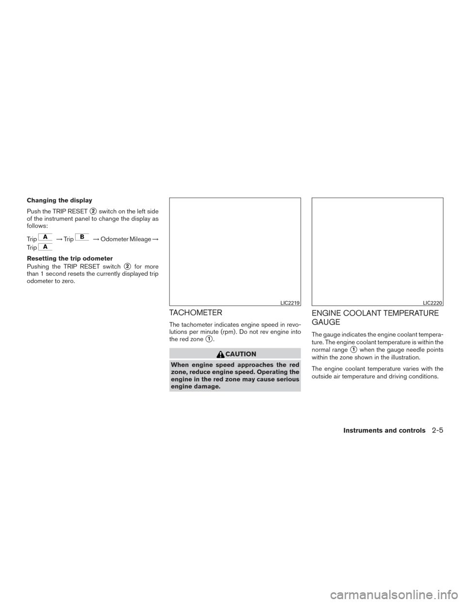
TACHOMETER
The tachometer indicates engine speed in revo-
lutions per minute (rpm) . Do not rev engine into
the red zone
�1.
CAUTION
When engine speed approaches the red
zone, reduce engine speed. Operating the
engine in the red zone may cause serious
engine damage.
ENGINE COOLANT TEMPERATURE
GAUGE
The gauge indicates the engine coolant tempera-
ture. The engine coolant temperature is within the
normal range
�1when the gauge needle points
within the zone shown in the illustration.
The engine coolant temperature varies with the
outside air temperature and driving conditions.
LIC2219LIC2220
Instruments and controls2-5
Page 85 of 497
 end of the normal
range, reduce vehicle speed to decrease
temperature. If the gauge is over the nor-
mal range, stop the vehicle a")
CAUTION
If the gauge indicates coolant tempera-
ture near the hot (H) end of the normal
range, reduce vehicle speed to decrease
temperature. If the gauge is over the nor-
mal range, stop the vehicle as soon as
safely possible. If the engine is over-
heated, continued operation of the vehicle
may seriously damage the engine. For ad-
ditional information, refer to “If your ve-
hicle overheats” in the “In case of emer-
gency” section of this manual for
immediate action required.
FUEL GAUGE
The gauge indicates theapproximatefuel level
in the tank.
The gauge may move slightly during braking,
turning, acceleration, or going up or down hills.
The gauge needle returns to 0 (Empty) after the
ignition switch is placed in the OFF position.
The low fuel warning message shows in the ve-
hicle information display when the amount of fuel
in the tank is getting low.
Refill the fuel tank before the gauge regis-
ters 0 (Empty) . The
indicates that the fuel-filler door is
located on the driver’s side of the vehicle.
CAUTION
● If the vehicle runs out of fuel, theMalfunction Indicator Light (MIL) may
come on. Refuel as soon as possible.
After a few driving trips, the
light
should turn off. If the light remains on
after a few driving trips, have the vehicle
inspected. It is recommended that you
visit a NISSAN dealer for this service.
● For additional information, refer to
“Malfunction Indicator Light (MIL)” in
this section.
LIC2222
2-6Instruments and controls
Page 200 of 497

●After parking in the sun, drive for 2 or 3 min-
utes with the windows open to vent hot air
from the passenger compartment. Then,
close the windows. This allows the air con-
ditioner to cool the interior more quickly.
● The air conditioning system should be
operated for approximately 10 minutes
at least once a month. This helps pre-
vent damage to the system due to lack
of lubrication.
● A visible mist may be seen coming from the
ventilators in hot, humid conditions as the air
is cooled rapidly. This does not indicate a
malfunction.
● If the engine coolant temperature
gauge indicates engine coolant tem-
perature over the normal range, turn
the air conditioner off. For additional
information, refer to “If your vehicle
overheats” in the “In case of emer-
gency” section of this manual.
AIR FLOW CHARTS
The following charts show the button and dial
positions for MAXIMUM AND QUICK heating,
cooling or defrosting. The air recirculation
button should always be in the OFF posi-
tion for heating and defrosting.
LHA3787
Monitor, climate, audio, phone and voice recognition systems4-21
Page 205 of 497

is activated depending on outside and cabin tem-
peratures. During this period, the climate control
display and buttons will be inoperable until the
ignition switch is turned on. In remote start de-
frosting mode, the rear defroster and heated
steering wheel (if so equipped) may be activated
automatically.
MANUAL OPERATION
Fan speed control
Press thefan speed control buttons to
manually control the fan speed.
Press the AUTO button to return to automatic
control of the fan speed.
Air recirculation
Press theair recirculation button to recir-
culate interior air inside the vehicle.
The air recirculation cannot be activated when
the air conditioner is in the
front defogging
mode.
Fresh air intake
Press thefresh air intake button to draw
outside air into the passenger compartment.
A/C (air conditioner) button
Start the engine, press thefan speed con-
trol buttons to the desired position and press the
button to turn on the air conditioner. To
turn off the air conditioner, press the
but-
ton again.
The air conditioner cooling function oper-
ates only when the engine is running.
Air flow control
Pressing the MODE button manually controls air
flow and selects the air outlet:
— Air flows from center and side
vents.
— Air flows from center and sidevents and foot outlets.
— Air flows mainly from foot outlets.
— Air flows from defroster and footoutlets.
To turn system off
Press the ON-OFF button.
OPERATING TIPS
●When the engine coolant temperature and
outside air temperature are low, the air flow
from the foot outlets may not operate for a
maximum of 150 seconds. However, this is
not a malfunction. After the coolant tempera-
ture warms up, air flow from the foot outlets
will operate normally. The sunload sensor, located on the top driver’s
side of the instrument panel, helps the system
maintain a constant temperature. Do not put any-
thing on or around this sensor.
LHA1136
4-26Monitor, climate, audio, phone and voice recognition systems

2. Engine coolant reservoir (P. 8-5)
3. Engine oil filler cap (P. 8-7)
4. Brake fluid reservoir (P. 8-12)
5. Air cleaner (P. 8-18)
6. Fuse/Fus")

2. Engine coolant reservoir (P. 8-5)
3. Engine oil filler cap (P. 8-7)
4. Brake fluid reservoir (P. 8-12)
5. Air cleaner (P. 8-18)
6. Fuse/Fus")

18. Cruise control main/set switches(if so equipped) (P. 5-41)
Intelligent Cruise Control (ICC)
switches (if so equipped) (P. 5-41)
Bluetooth® Hands-free Phon")