2017 MITSUBISHI OUTLANDER SPORT oil
[x] Cancel search: oilPage 356 of 399
Tires
Vehicle care and maintenance 9-19
9
N00939600241 N00939700141
The following maintenance steps are recom- mended:
Check tire pressures regularly. Have regular maintenance done on the wheel balance and front and rear suspen- sion alignment. Rotate your tires regularly as described in the “Tire rotation” section on page 9-19.
N00939800184
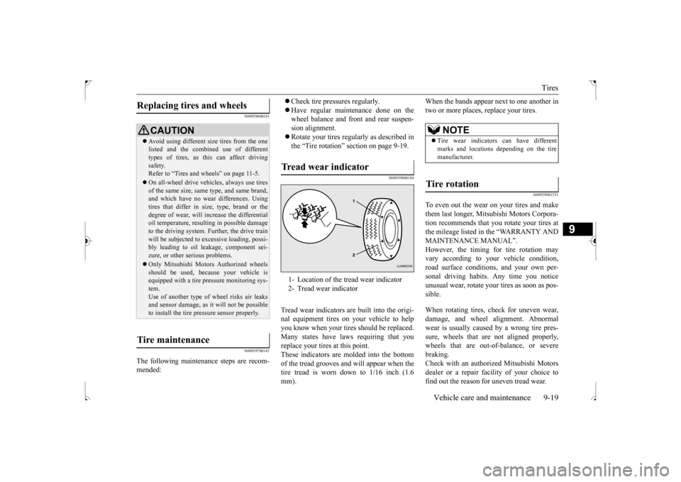
Tread wear indicators are built into the origi- nal equipment tires on your vehicle to helpyou know when your tires should be replaced. Many states have laws requiring that you replace your tires at this point.These indicators are molded into the bottom of the tread grooves and will appear when the tire tread is worn down to 1/16 inch (1.6mm).
When the bands appear next to one another in two or more places, replace your tires.
N00939901531
To even out the wear on your tires and makethem last longer, Mitsubishi Motors Corpora- tion recommends that you rotate your tires at the mileage listed in the “WARRANTY ANDMAINTENANCE MANUAL”. However, the timing for tire rotation may vary according to your vehicle condition,road surface conditions, and your own per- sonal driving habits. Any time you notice unusual wear, rotate your tires as soon as pos-sible. When rotating tires, check for uneven wear, damage, and wheel alignment. Abnormal wear is usually caused by a wrong tire pres-sure, wheels that are not aligned properly, wheels that are out-of-balance, or severe braking.Check with an authorized Mitsubishi Motors dealer or a repair faci
lity of your choice to
find out the reason for uneven tread wear.
Replacing tires and wheels
CAUTION Avoid using different size tires from the one listed and the combined use of different types of tires, as this can affect driving safety.Refer to “Tires and wheels” on page 11-5. On all-wheel drive vehicles, always use tires of the same size, same type, and same brand, and which have no wear differences. Using tires that differ in size, type, brand or thedegree of wear, will increase the differential oil temperature, resulting in possible damage to the driving system. Further, the drive trainwill be subjected to excessive loading, possi- bly leading to oil leakage, component sei- zure, or other serious problems. Only Mitsubishi Motors Authorized wheels should be used, because your vehicle isequipped with a tire pressure monitoring sys- tem. Use of another type of wheel risks air leaksand sensor damage, as it will not be possible to install the tire pressure sensor properly.
Tire maintenance
Tread wear indicator 1- Location of the tread wear indicator 2- Tread wear indicator
NOTE
Tire wear indicators can have different marks and locations depending on the tire manufacturer.
Tire rotation
BK0239500US.bo
ok 19 ページ 2016年5月13日 金曜日 午前8時53分
Page 361 of 399
For cold and snowy weather 9-24 Vehicle care and maintenance
9
N00941800077
Check the following parts for damage and grease leaks: Ball joint boots of the front suspension and steering linkage Bellows on both ends of the drive shaft
N00942200094
The best way to keep carbon monoxide gas from entering inside your vehicle is to have the engine exhaust system properly serviced. Have a competent mechanic inspect the com-plete exhaust system and nearby body areas for broken, damaged, deteriorated, or mispo- sitioned parts if you notice any of the follow-ing: A change in the sound of the exhaust sys- tem The smell of exhaust fumes inside the vehicle
The underside or rear of the vehicle is damaged
Also check the exhaust system each time the vehicle is raised for lubrication, oil changes, or required service. Any open seams or looseconnections could let dangerous exhaust fumes seep into the luggage compartment and passenger compartments. Check for holes or exhaust gas leaks caused by corrosion or damage. Check the joints and connections for looseness or exhaust gas leaks. Check the rubber hangers and brackets for damage.
N00942500101
The hood lock release mechanism and hood safety catch should be checked, cleaned, and oiled when needed for easy movement and tostop rust and wear. Use Multipurpose Grease NLGI Grade 2 sparingly for all sliding parts of the hood latch and release lever. Work thegrease into the hood lock mechanism until all the movable surfaces are covered.
Also, put a light coat of the same grease on the safety catch wherever moving parts touch.
N00942600102
The ventilation slots in front of the wind-shield should be brushed clear after a heavysnowfall so that the operation of the heating and ventilation systems will not be impaired. To prevent freezing of the weatherstripping on the doors, engine hood, etc., they should be treated with silicone grease. It is a good idea to carry a shovel or a short- handled spade in the vehicle during the win- ter so that you can clear away snow if you getstranded. A small hand-brush for sweeping snow off the vehicle and a plastic scraper for
Ball joint, steering linkage seals and drive shaft boots Exhaust system
WA R N I N G Carbon monoxide gas from your vehicle’s exhaust is poisonous. Breathing these fumes can cause unconsciousness or death.
Check for any of the following conditions: Hood lock release mechanism and safety catch
For cold and snowy weather Ventilation slots Weatherstripping Additional equipment (For regions where snow is encoun- tered)
BK0239500US.bo
ok 24 ページ 2016年5月13日 金曜日 午前8時53分
Page 364 of 399
Fuses
Vehicle care and maintenance 9-27
9
* : Fusible link Some fuses may not be installed on your vehicle, depending on the vehicle model or specifications. The table above shows the main equip- ment corresponding to each fuse. 20
Power window con-
trol
30 A
*
21 Defogger 30 A
*
22 Heated door mirror 7.5 A 23
Passenger’s power
seat
25 (20) A
24 Driver’s power seat
25 (20) A
25 Heated seats 30 ANo.
Sym- bol
Electrical system
Capac-ity
Engine compartment fuse location table No.
Sym- bol
Electrical system
Capac-ity
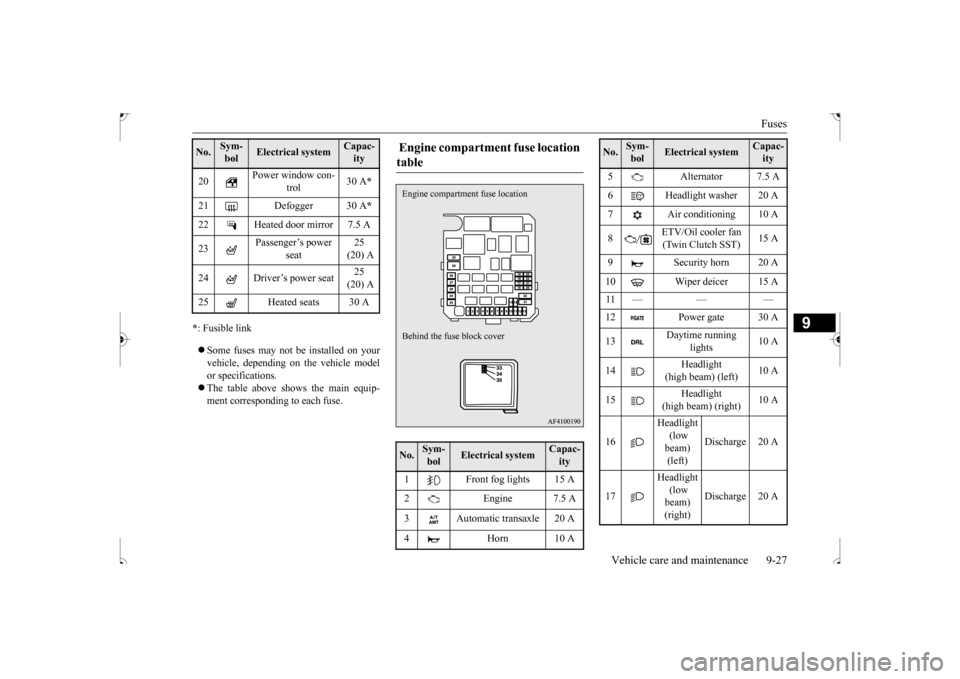
1 Front fog lights 15 A 2 Engine 7.5 A 3 Automatic transaxle 20 A 4 Horn 10 AEngine compartment
fuse location
Behind the fuse block cover
5 Alternator 7.5 A 6 Headlight washer 20 A 7 Air conditioning 10 A 8
ETV/Oil cooler fan (Twin Clutch SST)
15 A
9 Security horn 20 A 10 Wiper deicer 15 A 11 — — — 12 Power gate 30 A 13
Daytime running
lights
10 A
14
Headlight
(high beam) (left)
10 A
15
Headlight
(high beam) (right)
10 A
16
Headlight (low beam) (left)
Discharge 20 A
17
Headlight (low beam) (right)
Discharge 20 A
No.
Sym- bol
Electrical system
Capac-ity
BK0239500US.bo
ok 27 ページ 2016年5月13日 金曜日 午前8時53分
Page 365 of 399
Fuses 9-28 Vehicle care and maintenance
9
* : Fusible link Some fuses may not be installed on your vehicle, depending on the vehicle model or specifications. The table above shows the main equip- ment corresponding to each fuse.
There are no 7.5 A, 25 A or 30 A spare fuses. If a fuse of one of these capacities blows,replace it temporarily by borrowing one ofthe fuses indicated below. 7.5 A: 10 A spare fuse 25 A: 20 A spare fuse30 A: 30 A audio amplifier fuse Replace the borrowed fuse with a fuse that has the correct capacity as soon as possible.
N00954900128
1. Before replacing a fuse, always turn off the electrical item concerned to the fuse and turn the ignition switch to the “OFF”position or put the operation mode in OFF. 2. There is a fuse remover (A) in the enginecompartment fuse block.
18
Headlight (low beam) (left)
Halogen 10 A
19
Headlight (low beam) (right)
Halogen 10 A
20 ENG/POWER 10 A 21 Ignition coil 10 A 22
ENG/POWER 20 A Fuel line heater 25 A
23 Fuel pump 15 A 24 Starter 30 A
*
25 — — — 26
Anti-lock braking
system
40 A
*
27
Anti-lock braking
system
30 A
*
28
Air conditioning con- denser fan motor
30 A
*
29 Radiator fan 40 A
*
30 IOD IOD 30 ANo.
Sym- bol
Electrical system
Capac-ity
31 Audio amplifier 30 A 32 Diesel 30 A 33 — Spare fuse 10 A 34 — Spare fuse 15 A35 — Spare fuse 20 ANo.
Sym- bol
Electrical system
Capac-ity
Identification of fuse Capacity
Color
7.5 A Brown10 A Red15 A Blue20 A Yellow25 A Natural (white) 30 A
Green (fuse type) /Pink (fusible
link type)
40 A Green (fusible link type)
Fuse replacement
BK0239500US.bo
ok 28 ページ 2016年5月13日 金曜日 午前8時53分
Page 366 of 399
Replacement of light bulbs
Vehicle care and maintenance 9-29
9
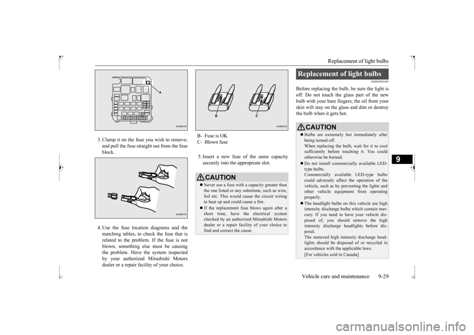
3. Clamp it on the fuse you wish to remove, and pull the fuse straight out from the fuse block. 4. Use the fuse location diagrams and the matching tables, to check the fuse that isrelated to the problem. If the fuse is notblown, something else must be causing the problem. Have the system inspected by your authorized Mitsubishi Motorsdealer or a repair facility of your choice.
5. Insert a new fuse of the same capacity securely into the appropriate slot.
N00942901405
Before replacing the bulb, be sure the light is off. Do not touch the glass part of the newbulb with your bare fingers; the oil from your skin will stay on the glass and dim or destroy the bulb when it gets hot.
B- Fuse is OKC- Blown fuse
CAUTION Never use a fuse with a capacity greater than the one listed or any substitute, such as wire, foil etc. This would cause the circuit wiring to heat up and could cause a fire. If the replacement fuse blows again after a short time, have the electrical systemchecked by an authorized Mitsubishi Motors dealer or a repair facility of your choice to find and correct the cause.
Replacement of light bulbs
CAUTION Bulbs are extremely hot immediately after being turned off.When replacing the bulb, wait for it to cool sufficiently before touching it. You could otherwise be burned. Do not install commercially available LED- type bulbs.Commercially available LED-type bulbs could adversely affect the operation of the vehicle, such as by preventing the lights andother vehicle equipment from operating properly. The headlight bulbs on this vehicle are high intensity discharge bulbs which contain mer- cury. If you need to have your vehicle dis-posed of, you should remove the high intensity discharge headlights before dis- posal. The removed high intensity discharge head- lights should be disposed of or recycled inaccordance with the applicable laws.[For vehicles sold in Canada]
BK0239500US.bo
ok 29 ページ 2016年5月13日 金曜日 午前8時53分
Page 370 of 399
Replacement of light bulbs
Vehicle care and maintenance 9-33
9
N00901901103
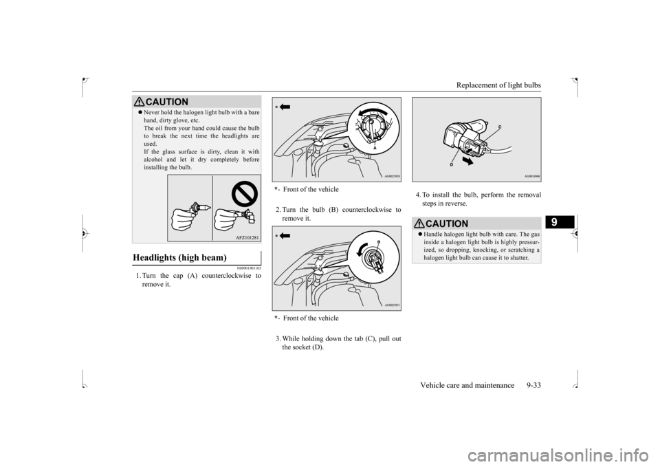
1. Turn the cap (A) counterclockwise to remove it.
2. Turn the bulb (B) counterclockwise to remove it. 3. While holding down the tab (C), pull out the socket (D).
4. To install the bulb, perform the removal steps in reverse.
Never hold the halogen light bulb with a bare hand, dirty glove, etc. The oil from your hand could cause the bulb to break the next time the headlights are used.If the glass surface is dirty, clean it with alcohol and let it dry completely before installing the bulb.
Headlights (high beam)
CAUTION
* - Front of the vehicle * - Front of the vehicle
CAUTIONHandle halogen light bulb with care. The gas inside a halogen light bulb is highly pressur-ized, so dropping, knocking, or scratching a halogen light bulb can cause it to shatter.
BK0239500US.bo
ok 33 ページ 2016年5月13日 金曜日 午前8時53分
Page 371 of 399
Replacement of light bulbs 9-34 Vehicle care and maintenance
9
N00900300099
Do not attempt to disassemble or repair head- lights, and do not attempt to replace their bulbs.
N00943200121
The alignment of the headlights should bechecked by an authorized Mitsubishi Motorsdealer or a repair facility of your choice.
N00917301737
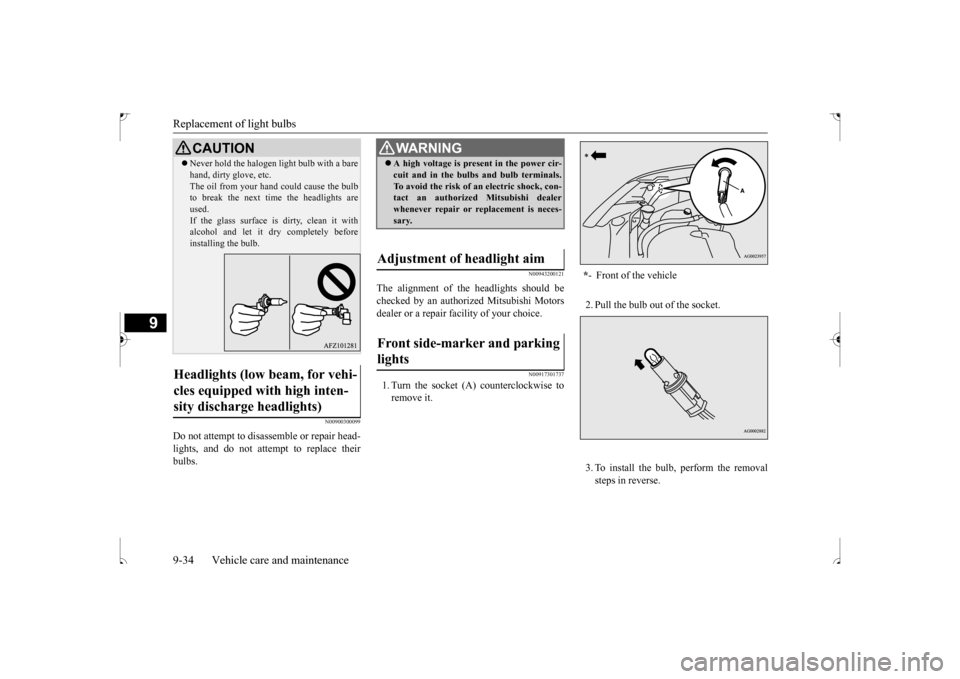
1. Turn the socket (A) counterclockwise to remove it.
2. Pull the bulb out of the socket. 3. To install the bulb, perform the removal steps in reverse.
Never hold the halogen light bulb with a bare hand, dirty glove, etc. The oil from your hand could cause the bulb to break the next time the headlights are used.If the glass surface is dirty, clean it with alcohol and let it dry completely before installing the bulb.
Headlights (low beam, for vehi- cles equipped with high inten- sity discharge headlights)
CAUTION
WA R N I N G A high voltage is present in the power cir- cuit and in the bulbs and bulb terminals. To avoid the risk of an electric shock, con- tact an authorized Mitsubishi dealer whenever repair or replacement is neces-sary.
Adjustment of headlight aim Front side-marker and parking lights
* - Front of the vehicle
BK0239500US.bo
ok 34 ページ 2016年5月13日 金曜日 午前8時53分
Page 374 of 399
Replacement of light bulbs
Vehicle care and maintenance 9-37
9
N00900301184
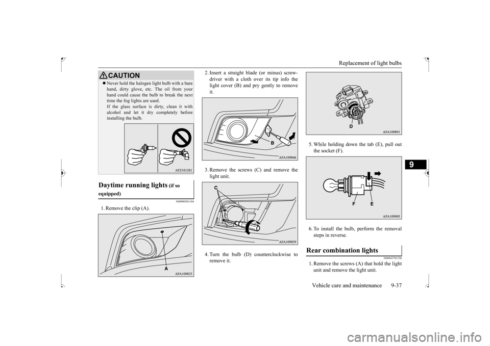
1. Remove the clip (A).
2. Insert a straight blade (or minus) screw- driver with a cloth over its tip info the light cover (B) and pry gently to remove it. 3. Remove the screws (C) and remove the light unit. 4. Turn the bulb (D) counterclockwise to remove it.
5. While holding down the tab (E), pull out the socket (F). 6. To install the bulb, perform the removal steps in reverse.
N00943701530
1. Remove the screws (A) that hold the light unit and remove the light unit.
Never hold the halogen light bulb with a bare hand, dirty glove, etc. The oil from your hand could cause the bulb to break the next time the fog lights are used. If the glass surface is dirty, clean it withalcohol and let it dry completely before installing the bulb.
Daytime running lights
(if so
equipped)
CAUTION
Rear combination lights
BK0239500US.bo
ok 37 ページ 2016年5月13日 金曜日 午前8時53分