2017 MITSUBISHI OUTLANDER horn
[x] Cancel search: hornPage 112 of 521
Free-hand Advanced Securi
ty Transmitter (F.A.S.T.-key) (if so equipped)
Features and controls 5-31
5
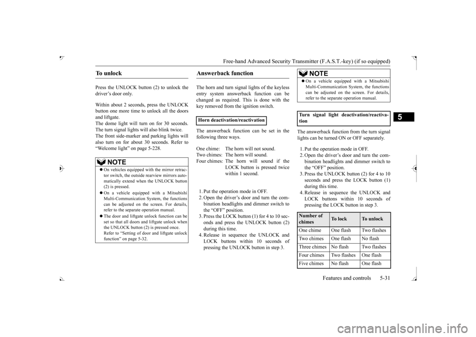
Press the UNLOCK button (2) to unlock the driver’s door only. Within about 2 seconds, press the UNLOCK button one more time to unlock all the doorsand liftgate. The dome light will turn on for 30 seconds. The turn signal lights will also blink twice. The front side-marker
and parking lights will
also turn on for about 30 seconds. Refer to“Welcome light” on page 5-228.
The horn and turn signal lights of the keyless entry system answerback function can be changed as required. This is done with thekey removed from the ignition switch. The answerback function can be set in the following three ways. 1. Put the operation mode in OFF. 2. Open the driver’s door and turn the com- bination headlights a
nd dimmer switch to
the “OFF” position.3. Press the LOCK button (1) for 4 to 10 sec- onds and press the UNLOCK button (2) during this time.4. Release in sequence the UNLOCK and LOCK buttons within 10 seconds of pressing the UNLOCK button in step 3.
The answerback function from the turn signal lights can be turned ON or OFF separately. 1. Put the operation mode in OFF. 2. Open the driver’s door and turn the com- bination headlights and dimmer switch tothe “OFF” position. 3. Press the UNLOCK button (2) for 4 to 10 seconds and press the LOCK button (1)during this time. 4. Release in sequence the UNLOCK and LOCK buttons within 10 seconds ofpressing the LOCK button in step 3.
To u n l o c k
NOTE
On vehicles equipped wi
th the mirror retrac-
tor switch, the outside rearview mirrors auto- matically extend when
the UNLOCK button
(2) is pressed. On a vehicle equippe
d with a Mitsubishi
Multi-Communication System, the functionscan be adjusted on the screen. For details, refer to the separa
te operation manual.
The door and liftgate unlock function can be set so that all doors and liftgate unlock when the UNLOCK button (2) is pressed once.Refer to “Setting of door
and liftgate unlock
function” on page 5-32.
Answerback function
Horn deactivation/reactivation One chime: The horn will not sound. Two chimes: The horn will sound.Four chimes: The horn will sound if the
LOCK button is pressed twice within 1 second.
NOTE
On a vehicle equipped with a Mitsubishi Multi-Communication System, the functionscan be adjusted on the screen. For details,refer to the separa
te operation manual.
Turn signal light deactivation/reactiva- tionNumber of chimes
To l o c k
To u n l o c k
One chime One flash Two flashes Two chimes One flash No flash Three chimes No flash Two flashes Four chimes Two flashes One flash Five chimes No flash One flash
BK0239700US.book 31 ページ 2016年6月16日 木曜日 午前10時58分
Page 113 of 521
Free-hand Advanced
Security Transmitter (F.A.S
.T.-key) (if so equipped)
5
The buzzer answerback function can be turned ON or OFF as required.
N00544601095
The door and liftgate
unlock function can be
set to the following two conditions. Each time the door and
liftgate unlock func-
tion is set, a chime wi
ll sound to tell you the
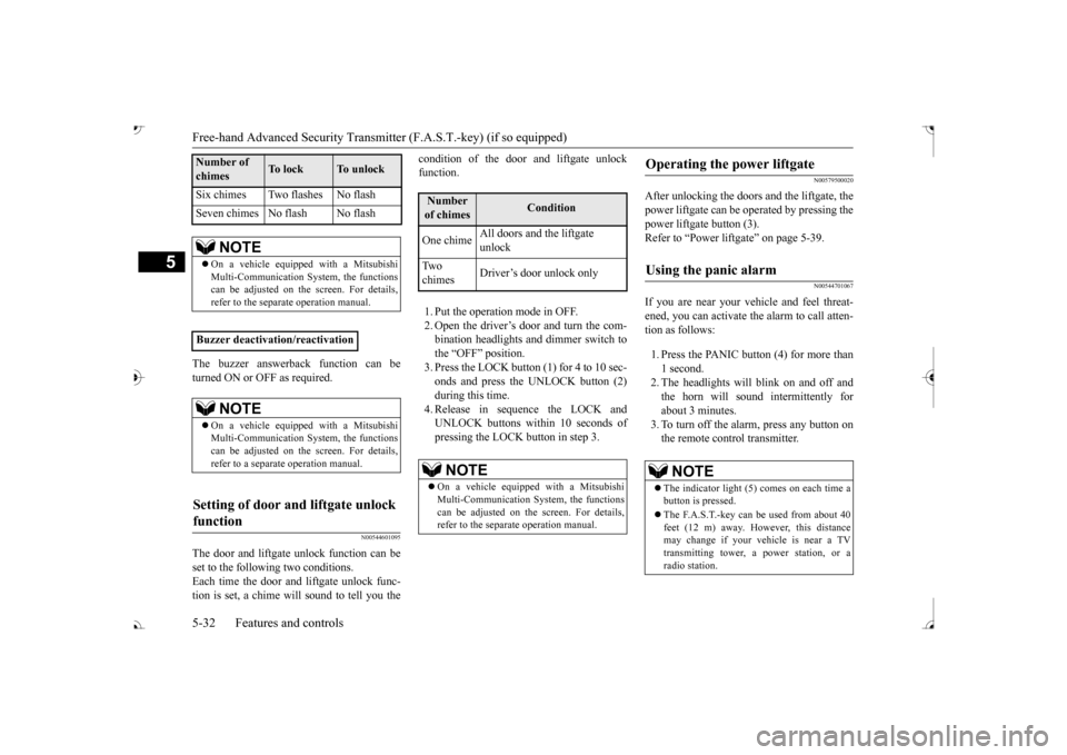
condition of the door and liftgate unlock function. 1. Put the operation mode in OFF. 2. Open the driver’s door and turn the com- bination headlights and dimmer switch tothe “OFF” position. 3. Press the LOCK button (1) for 4 to 10 sec- onds and press the UNLOCK button (2)during this time. 4. Release in sequence the LOCK and UNLOCK buttons within 10 seconds ofpressing the LOCK button in step 3.
N00579500020
After unlocking the doors and the liftgate, the power liftgate can be operated by pressing the power liftgate button (3).Refer to “Power lift
gate” on page 5-39.
N00544701067
If you are near your vehicle and feel threat- ened, you can activate the alarm to call atten- tion as follows: 1. Press the PANIC button (4) for more than 1 second. 2. The headlights will blink on and off and the horn will sound intermittently forabout 3 minutes. 3. To turn off the alarm, press any button on the remote control transmitter.
Six chimes Two flashes No flash Seven chimes No flash No flash
NOTE
On a vehicle equippe
d with a Mitsubishi
Multi-Communication System, the functions can be adjusted on the screen. For details, refer to the separate operation manual.
Buzzer deactivation/reactivation
NOTE
On a vehicle equippe
d with a Mitsubishi
Multi-Communication System, the functionscan be adjusted on the screen. For details, refer to a separa
te operation manual.
Setting of door and liftgate unlock function
Number of chimes
To l o c k
To unlock
Number of chimes
Condition
One chime
All doors and the liftgate unlock
Tw o chimes
Driver’s door unlock only
NOTE
On a vehicle equippe
d with a Mitsubishi
Multi-Communication System, the functions can be adjusted on the screen. For details, refer to the separa
te operation manual.
Operating the power liftgate
Using the panic alarm
NOTE
The indicator light (5) comes on each time a button is pressed. The F.A.S.T.-key can be used from about 40 feet (12 m) away. However, this distance may change if your vehicle is near a TVtransmitting tower, a power station, or a radio station.
BK0239700US.book 32 ページ 2016年6月16日 木曜日 午前10時58分
Page 129 of 521
Theft-alarm system 5-48 Features and controls
5
N00582500040
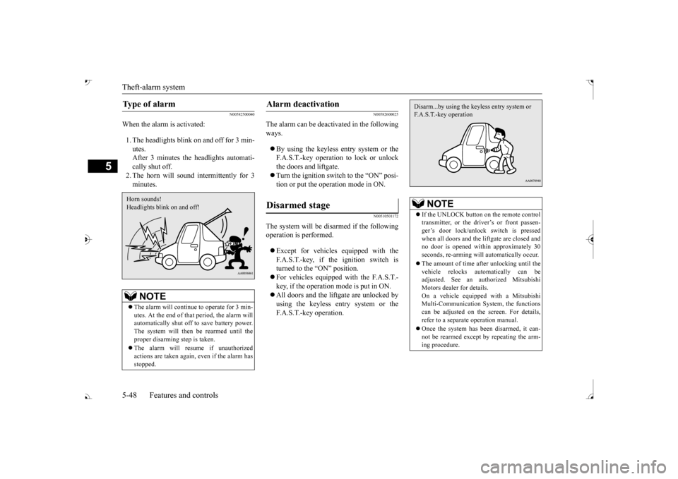
When the alarm is activated: 1. The headlights blink on and off for 3 min- utes. After 3 minutes the headlights automati-cally shut off. 2. The horn will sound intermittently for 3 minutes.
N00582600025
The alarm can be deacti
vated in the following
ways. By using the keyless entry system or the F.A.S.T.-key operation to lock or unlockthe doors and liftgate. Turn the ignition switch to the “ON” posi- tion or put the operation mode in ON.
N00510501172
The system will be disarmed if the followingoperation is performed. Except for vehicles equipped with the F.A.S.T.-key, if the ignition switch is turned to the “ON” position. For vehicles equipped with the F.A.S.T.- key, if the operation mode is put in ON. All doors and the lift
gate are unlocked by
using the keyless entry system or the F.A.S.T.-key operation.
Type of alarm
NOTE
The alarm will continue
to operate for 3 min-
utes. At the end of that
period, the alarm will
automatically shut off
to save battery power.
The system will then be rearmed until theproper disarming step is taken. The alarm will resu
me if unauthorized
actions are taken again, even if the alarm has stopped.Horn sounds! Headlights blink on and off!
Alarm deactivation Disarmed stage
NOTE
If the UNLOCK button on the remote control transmitter, or the driver’s or front passen-ger’s door lock/unlock switch is pressed when all doors and the li
ftgate are closed and
no door is opened with
in approximately 30
seconds, re-arming will
automatically occur.
The amount of time after unlocking until the vehicle relocks automatically can be adjusted. See an authorized Mitsubishi Motors dealer for details.On a vehicle equippe
d with a Mitsubishi
Multi-Communication System, the functions can be adjusted on the screen. For details,refer to a separa
te operation manual.
Once the system has been disarmed, it can- not be rearmed except
by repeating the arm-
ing procedure.Disarm...by using the keyless entry system or F.A.S.T.-key operation
BK0239700US.book 48 ページ 2016年6月16日 木曜日 午前10時58分
Page 130 of 521
Power window control
Features and controls 5-49
5
N00510601157
Use the following procedure to test the sys- tem: 1. Lower the driver’s window. 2. Arm the system as explained in “Armedstage”. comes on and flashe
s for approximately
20 seconds. 4. Wait a few seconds and then unlock thedriver’s side door by using the inside door lock knob. Open the door. 5. Make sure that the horn sounds intermit-tently and the headlights blink when a door is opened. 6. Disarm the system by unlocking all doorsand the liftgate by using the keyless entry system or the F.A.S.T.-key operation.
N00510800383
Testing the theft-alarm system
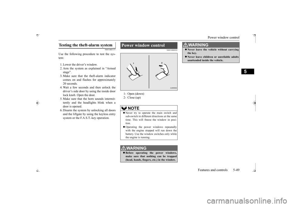
Power window control 1- Open (down) 2- Close (up)
NOTE
Never try to operate the main switch and sub-switch in different
directions at the same
time. This will free
ze the window in posi-
tion. Operating the power windows repeatedly with the engine stoppe
d will run down the
battery. Use the window
switches only while
the engine is running.WA R N I N G Before operating the power windows, make sure that nothing can be trapped (head, hands, fingers, etc.) in the window.
Never leave the vehicle without carrying the key. Never leave children
or unreliable adults
unattended inside the vehicle.WA R N I N G
BK0239700US.book 49 ページ 2016年6月16日 木曜日 午前10時58分
Page 320 of 521
Heated steering wheel switch (if so equipped)
Features and controls 5-239
5
N00589100032
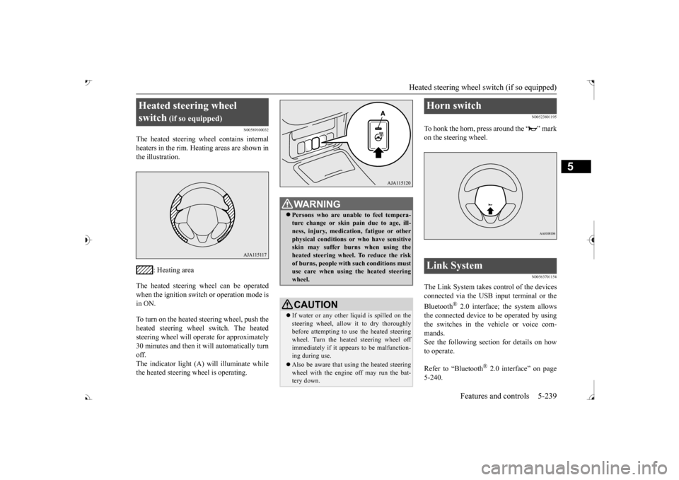
The heated steering wh
eel contains internal
heaters in the rim. Heating areas are shown in the illustration.
: Heating area
The heated steering wheel can be operated when the ignition switch or operation mode is in ON. To turn on the heated steering wheel, push the heated steering wheel switch. The heated steering wheel will ope
rate for approximately
30 minutes and then it
will automatically turn
off. The indicator light (A) will illuminate while the heated steering wheel is operating.
N00523801195
To honk the horn, press around the “ ” markon the steering wheel.
N00563701154
The Link System takes control of the devicesconnected via the USB input terminal or the Bluetooth
® 2.0 interface; the system allows
the connected device to be operated by using the switches in the vehicle or voice com-mands. See the following section for details on how to operate. Refer to “Bluetooth
® 2.0 interface” on page
5-240.
Heated steering wheel switch
(if so equipped)
Persons who are unable
to feel tempera-
ture change or skin
pain due to age, ill-
ness, injury, medicati
on, fatigue or other
physical conditions or
who have sensitive
skin may suffer burns when using theheated steering wheel. To reduce the risk of burns, people with such conditions must use care when using the heated steeringwheel.CAUTION If water or any other li
quid is spilled on the
steering wheel, allow it to dry thoroughly before attempting to use the heated steering wheel. Turn the heated steering wheel offimmediately if it appe
ars to be malfunction-
ing during use. Also be aware that us
ing the heated steering
wheel with the engine off may run the bat- tery down.
Horn switch Link System
BK0239700US.book 239 ページ 2016年6月16日 木曜日 午前10時58分
Page 482 of 521

Fuses
Vehicle care and maintenance 9-29
9
*: Fusible link
SBF2 Starter 30 A* SBF3
Air condition- ing condenser fan motor
30 A*
SBF4
Radiator fan
motor
40 A*
SBF5
Anti-lock brak- ing system
40 A*
SBF6
Electric parking
brake
50 A*
SBF7
Anti-lock brak- ing system
30 A*
BF1 Power liftgate 30 A BF2
Audio system amplifier
30 A
BF3 IOD IOD 30 A BF4 Diesel 30 A F1
Automatic transaxle
20 A
F2 Wiper de-icer 15A F3
Electric parking
brake
7.5 A
F4
Daytime run- ning lights
10 A
No.
Sym- bol
Electrical sys-
tem
Capacity
F5 Front fog lights 15 A F6 Air conditioner 10 A F7
Headlight washer
20 A
F8 Security horn 20 A F9 Horn 10 A F10 ETV 15 AF11 Alternator 7.5 AF12 Engine 7.5 A F13
ENG/POWER 20 A Fuel line heater 25 A
F14 Fuel pump 15 A F15 Ignition coil 10 AF16 ENG/POWER 10 A F17
Headlight (high beam) (left)
10 A
F18
Headlight (high beam) (right)
10 A
No.
Sym- bol
Electrical sys-
tem
Capacity
F19
Head- light (low beam) (left)
LED 20 A
F20
Head- light (low beam) (right)
LED 20 A
F21
Head- light (low beam) (left)
Halo- gen
10 A
F22
Head- light (low beam) (right)
Halo- gen
10 A
F23
Battery current
sensor
7.5 A
#1 — Spare fuse 10 A #2 — Spare fuse 15 A #3 — Spare fuse 20 ANo.
Sym- bol
Electrical sys-
tem
Capacity
BK0239700US.book 29 ページ 2016年6月16日 木曜日 午前10時58分
Page 516 of 521

Alphabetical index
12-3
12
Replacement
..................................
9-36
Switch
.........................................
5-231
Front side-marker lights
Bulb capacity
.................................
9-32
Replacement
..................................
9-35
Front turn signal light
Bulb capacity
.................................
9-32
Replacement
..................................
9-36
Fuel
Filling the fuel tank
...........................
3-3
Fuel economy
...................................
6-2
Fuel hoses
......................................
9-23
Fuel selection
...................................
3-2
Tank capacity
.................................
11-7
Fuel Pump Shut-off System
.................
8-16
Fuses
.................................................
9-25
Fusible links
.......................................
9-25
G
General maintenance
...........................
9-23
General vehicle data
............................
11-4
Genuine parts
.......................................
3-7
Glove compartment
...........................
5-276
Glove compartment light
Bulb capacity
.................................
9-33
H
Hazard warning
flasher switch
...........
5-231
Hazard warning lights
........................
5-215
Head restraints
...................................
4-11
Headlight leveling switch
...................
5-229
Headlights
Bulb capacity
.................................
9-32
Dimmer
........................................
5-223
Headlight flasher
...........................
5-224
Replacement
..........................
9-34
, 9-35
Switch
..........................................
5-220
Heated steering wheel switch
..............
5-239
High beam indicator
..........................
5-215
High-mounted stop light
Bulb capacity
.................................
9-32
Hill start assist
...................................
5-95
HomeLink® Wireless
Control System
.5-268
Hood lock release me
chanism and safety
catch
...............................................
9-25
Horn switch
......................................
5-239
I
If the vehicle breaks down
.....................
8-2
Ignition switch
...................................
5-63
Important facts to know in
case of an accident
10-4 Indicators
....................
5-191
, 5-214
, 5-215
Information screen display
.................
5-192
Inside rearview mirror
.........................
5-57
Inspection and maintenance following rough road operation
..................................
5-91
Instrument cluster
.............................
5-163
Interior lights
....................................
5-273
J
Jack
.....................................................
8-5
Storage
............................................
8-5
Jump-starting the engine
........................
8-2
K
Keyless entry system
....................
5-7
, 5-30
Keys
....................................................
5-3
L
Labeling
.............................................
11-2
Lane Departure Warning System (LDW)
.....
5-139 License plate light
Bulb capacity
.................................
9-32
Replacement
...................................
9-39
Liftgate
..............................................
5-38
Link System
.....................................
5-239
Loading information
..............................
6-6
Lubricants
..........................................
11-7
Luggage floor box
.............................
5-277
Luggage hooks
.................................
5-283
BK0239700US.book 3 ページ 2016年6月16日 木曜日 午前10時58分