2017 MITSUBISHI MIRAGE wheel pressure
[x] Cancel search: wheel pressurePage 8 of 307

Outside
Overview 1-6
1
High-mounted stop light P.9-27
Tire pressure monitoring system (if so equipped) P.5-58 Changing tires P.8-6Size of tires and wheels P.11-5 Tire inflation pressure P.9-15 Tire rotation P.9-17Tire chains P.9-18
Trunk lid P.5-27
Tail and stop lights P.5-79, 9-27, 9-30
Rear-view camera (if so equipped) P.5-62
Rear turn signal lights P.5-81, 9-27, 9-30
License plate lights P.5-79, 9-27, 9-31
Back-up light P.9-27, 9-30
Antenna P.7-44
Rear side- marker lights P.5-79, 9-27, 9-30
BK0236100US.book 6 ページ 2016年2月1日 月曜日 午前10時15分
Page 62 of 307

5
Features and controlsBreak-in recommendations ..............................................................5-2 Keys .................................................................................................5-2 Electronic immobilizer (Anti-theft starting system) ........................5-3Keyless entry system (if so equipped) ..............................................5-6 Free-hand Advanced Security
Transmitter (F.A.S.T.-key)
(if so equipped) ............................................................................5-9Door locks ......................................................................................5-24 Power door locks ......
...........
...........
...........
...........
...........
.........
.....5-25
Child safety locks for rear door ..........
...........
.........
.........
.........
.....5-26
Trunk lid ................
............
...........
...........
...........
...........
...........
.....5-27
Inside emergency trunk lid release ................................................5-28 Manual window control (if so equipped)........................................5-29Power window control ...................................................................5-29 Parking brake .................................................................................5-32 Steering wheel height adjustment ..................................................5-33Inside rearview mirror ...................................................................5-34 Outside rearview mirrors ...............................................................5-36 Ignition switch ...............................................................................5-37Starting the engine .........................................................................5-38 Manual transaxle (if so equipped) ..................................................5-40 Continuously variable transmission
(CVT) (if so equipped)..........5-42
Service brake .................................................................................5-46 Hill start assist ................................................................................5-47 Brake assist system ........................................................................5-49Anti-lock braking system ...............................................................5-49 Electric power steering system (EPS) ............................................5-51 Active stability control (ASC) .......................................................5-52Cruise control (if so equipped) .......................................................5-54
Tire pressure monitoring system (if so equipped) .......................... 5-58 Rear-view camera (if so equipped)................................................. 5-62 Instrument cluster .......................................................................... 5-64Multi-information display ............................................................. 5-65 Indicator and warning light package ............................................. 5-75 Indicators ....................................................................................... 5-76Warning lights ................................................................................ 5-76 Combination headlights and dimmer switch ................................. 5-79 Turn signal lever ............................................................................ 5-81Hazard warning flasher switch ...................................................... 5-82 Front fog light switch (if so equipped) .......................................... 5-82 Wiper and washer switch ............................................................... 5-82Electric rear window defogger switch ....
...........
...........
...........
...... 5-84
Horn switch ................................................................................... 5-85 Link System (if so equipped) ......................................................... 5-85 Bluetooth
® 2.0 interface (if so equipped)....................................... 5-85
USB input terminal (if so
equipped) ....
...........
.........
........
........... 5-105
Sun visors .................................................................................... 5-10912 V power outlets ....................................................................... 5-110 HomeLink
® Wireless Control System (if so equipped) ............... 5-110
Interior lights ............................................................................... 5-115Storage spaces .............................................................................. 5-116 Cup holders .................................................................................. 5-117 Bottle holders ............................................................................... 5-118Convenience hook ............
...........
...........
...........
...........
...........
.... 5-118
Assist grips .................................................................................. 5-119
BK0236100US.book 1 ページ 2016年2月1日 月曜日 午前10時15分
Page 119 of 307

Tire pressure monitoring
system (if so equipped)
5-58 Features and controls
5
When the active stability control (ASC) starts operating.Refer to “Active stab
ility control (ASC)”
on page 5-52.
Also, the set speed driving may be deacti- vated automatically when the engine speed rises and approaches the tachometer’s redzone (the red-colored part of the tachometer dial).
N00518900306
If the set speed driving is deactivated by thecondition described in “To deactivate” on page 5-57, you can resu
me the previously set
speed by pressing the RES + switch (C) while driving at a speed of about 25 mph (40 km/h) or higher. Under either of the
following conditions,
however, using the sw
itch does not allow you
to resume the previously set speed. In these situations, repeat the
speed setting procedure:
The CRUISE CONTROL ON/OFF switch is pressed. [Except for vehicles equipped with the F. A . S . T. - k e y ] Turn the ignition switch to the “OFF” or “ACC” position. [Vehicles equipped with the F.A.S.T.-key]
Put the operation mode in OFF or ACC. Indicator is turned OFF.
N00530201612
The tire pressure moni
toring system uses tire
inflation pressure sensors (A) on the wheelsto monitor the tire inflation pressures. The system only indicates wh
en a tire is signifi-
cantly under-inflated.
WA R N I N G On vehicles equipped with continuously variable transmis
sion (CVT), although the
set speed driving will be deactivated whenshifting to the “N” never move the select
or lever to the “N”
You would have no engine braking and could cause a serious accident.CAUTION When the set speed dr
iving is deactivated
automatically in any
situation other than
those listed above, there may be a systemmalfunction. Press the CRUISE CONTROL ON/OFF switch to turn off the
cruise control and have
your vehicle inspecte
d by an authorized
Mitsubishi Motors dealer
or a repair facility
of your choice.
To resume the set speed
Tire pressure monitoring system
(if so equipped)
BK0236100US.book 58 ページ 2016年2月1日 月曜日 午前10時15分
Page 121 of 307

Tire pressure monitoring
system (if so equipped)
5-60 Features and controls
5
Each tire, including the spare, should be checked monthly when cold and inflated tothe inflation pressure recommended by the vehicle manufac
turer on the vehicle placard
or tire inflation pressu
re label. (If your vehi-
cle has tires of a different size than the size indicated on the vehicle
placard or tire infla-
tion pressure label, yo
u should determine the
proper tire inflation pr
essure for those tires.)
As an added safety feature, your vehicle has been equipped with a tire pressure monitoring system (TPMS) that illuminates a low tire pressure telltale when
one or more of your
tires is significant
ly under-inflated.
Accordingly, when the low tire pressure tell- tale illuminates, you should stop and checkyour tires as soon as possible, and inflate them to the proper pressure. Driving on a sig- nificantly under-inflated
tire causes the tire to
overheat and can lead
to tire failure.
Under-inflation also reduces fuel efficiency and tire tread life, and may affect the vehi-cle’s handling and stopping ability. Please note that the TPMS is not a substitute for proper tire maintenance, and it is the driver’sresponsibility to mainta
in correct tire pres-
sure, even if under-inf
lation has not
reached
the level to trigger illumination of the TPMSlow tire pressure telltale. Your vehicle has also been equipped with a TPMS malfunction indicator to indicate when
the system is not operating properly. The TPMS malfunction indicator is combinedwith the low tire pressure telltale. When the system detects a malfunction, the telltale will flash for approximately one min-ute and then remain c
ontinuously illuminated.
This sequence will c
ontinue upon subsequent
vehicle start-ups as long as the malfunctionexists. When the malfunction indicator is illumi- nated, the system may not
be able to detect or
signal low tire pr
essure as intended.
TPMS malfunctions may
occur for a variety
of reasons, including the installation of replacement or alternate tires or wheels on the vehicle that prevent the TPMS from function-ing properly. Always
check the TPMS mal-
function telltale after replacing one or more tires or wheels on your vehicle to ensure thatthe replacement or alternate tires and wheels allow the TPMS to continue to function prop- erly.
N00532801540
1. If the tire pressure monitoring systemwarning light illum
inates, avoid hard
braking, sharp steering maneuvers and high speeds. You should stop and adjust the tires to the proper inflation pressure assoon as possible. Adjust the spare tire at the same time. Refer to “Tires” on page 9-12.
If the warning light illuminates while driving
NOTE
When inspecting or adjusting the tire pres- sure, do not apply excessive force to the valve stem to
avoid breakage.
After inspecting or adjusting the tire pres- sure, always reinstall the valve cap on thevalve stem. Without the valve cap, di
rt or moisture could
get into the valve, resulting in damage to thetire inflation pressure sensor. Do not use metal valve caps, which may cause a metal reaction,
resulting in corrosion
and damage of the tire
inflation pressure sen-
sors. Once adjustments have
been made, the warn-
ing light will go off after a few minutes ofdriving.
BK0236100US.book 60 ページ 2016年2月1日 月曜日 午前10時15分
Page 122 of 307

Tire pressure monitoring system (if so equipped)
Features and controls 5-61
5
2. If the tire pressure monitoring system warning light remain
s illuminated after
you have been driving for about 20 min- utes after you adjust the tire inflation pres- sure, one or more of the tires may have apuncture. Inspect the ti
re and if it has a
puncture, have it re
paired by an autho-
rized Mitsubishi Motors dealer as soon aspossible.
The tire pressure monitoring system may not work normally in the following circum- stances: A wireless facility
or device using the
same frequency is near the vehicle. Snow or ice is stuck inside the fenders and/or on the wheels. The tire inflation pressure sensor’s battery is dead. Wheels other than Mitsubishi Genuine wheels are being used. Wheels that are not fitted with tire infla- tion pressure sensors are being used. Wheels whose ID codes are not memo- rized by the vehicle are used. Compact spare tire is fitted on a road wheel. A window tint that af
fects the radio wave
signals is installed.
N00532900153
If new wheels with new tire inflation pressuresensors are installed,
their ID codes must be
programmed into the tire pressure monitoring system. Have tire and
wheel replacement per-
formed by an authorized Mitsubishi Motors dealer to avoid the risk of damaging the tire inflation pressure sensors. If the wheelreplacement is not done by an authorized Mitsubishi Motors dealer
, it is not covered by
your warranty.
WA R N I N G If the warning light illuminates while you are driving, avoid ha
rd braking, sharp
steering maneuvers and high speeds. Driving with an under-inflated tire adversely affe
cts vehicle performance and
can result in an accident.CAUTION The warning light may
not illuminate imme-
diately in the event of
a tire blowout or rapid
leak.NOTE
To avoid the risk of da
mage to the tire infla-
tion pressure sensors, have any puncturedtire repaired by an authorized Mitsubishi Motors dealer. If the tir
e repair is not done by
an authorized Mitsubishi Motors dealer,damage to the tire infl
ation pressure sensor is
not covered by your warranty.
Do not use an aerosol puncture-repair spray on any tire.Such a spray could dama
ge the tire inflation
pressure sensors. Have any puncture repa
ired by an authorized
Mitsubishi Moto
rs dealer.
NOTE
NOTE
Tire inflation pressures vary with the ambi- ent temperature. If the vehicle is subjected tolarge variations in ambient temperature, thetire inflation pressures may be under-inflated (causing the warning light come on) when the ambient temperature is relatively low. Ifthe warning light comes on, adjust the tire inflation pressure.
Whenever the tires and wheels are replaced with new ones
CAUTION The use of non-genuine wheels will prevent the proper fit of the tire inflation pressure sensors, resulting air
leakage or damage of
the sensors.
BK0236100US.book 61 ページ 2016年2月1日 月曜日 午前10時15分
Page 184 of 307

Vehicle preparatio
n before driving
Driving safety 6-3
6
N00629001770
For a safer and more enjoyable trip, always check for the following: Before starting the vehicle, make certain that you and all passengers are seated andwearing their seat
belts properly (with
children in the rear seat, in appropriate restraints), and that all the doors arelocked.
Move the driver’s seat as far backward as possible, while keeping good visibility,and good control of the steering wheel, brakes, accelerator, and controls. Check the instrument panel indicators and multi-information display for any possible prob- lem. Similarly, the front
passenger seat should
also be moved as fa
r back as possible.
Make sure that infants and small children are properly restrained in accordance with all laws and regulations.
Check these by selectin
g the defroster mode,
and set the blower switch on high. You should be able to feel the air blowing against thewindshield. Refer to “Defrosti
ng or defogging (wind-
shield, door windows)” on page 7-6, 7-10,7-17. Check all the tires for heavy tread wear or uneven wear patterns. Look for stones, nails, glass, or other objects
stuck in the tread. Look
for any tread cuts or
sidewall cracks. Check
the wheel nuts for tightness, and the tires (including spare tire) for proper pressure.
WA R N I N G If a floor mat is the
wrong size or is not
properly installed, it can interfere with theoperation of the pedals. Interference withthe pedals can cause unintended accelera- tion and/or increase
d stopping distances
resulting in a cras
h and injury. Always
make sure the floor mat does not interfere with the accelerator or brake pedal. Always use the retaining clip on the driver’s floorboard to secure the floor mat. Always install the mat with the correct side facing down. Never install a second mat over or under an existing floor mat. Do not use a floor mat designed for another model vehicle even if it is aMitsubishi genu
ine floor mat.
Before driving, be sure to check the fol- lowing:• Periodically check that the floor mat isproperly secured with the retaining clips. If you remove the fl
oor mat while clean-
ing the inside of you
r vehicle or for any
other reason, always
check the condition
of the floor mat afte
r it has been rein-
stalled.• While the vehicle is stopped with theengine off, check that
the floor mat is not
interfering with the pedals by depressing the pedals fully.
Vehicle preparation before driving Seat belts and seats
Defrosters Tires
BK0236100US.book 3 ページ 2016年2月1日 月曜日 午前10時15分
Page 246 of 307
How to change a tire
For emergencies 8-7
8
6. Get the jack, bar and wheel nut wrench ready. (Refer to “Jack and t
ools” on page 8-5.)
N00849600344
The compact spare tire is stowed beneath the floor board of the cargo area. It is designed to save space in the cargo area. Its lighter weightmakes it easier to use if a flat tire occurs.
N00849701371
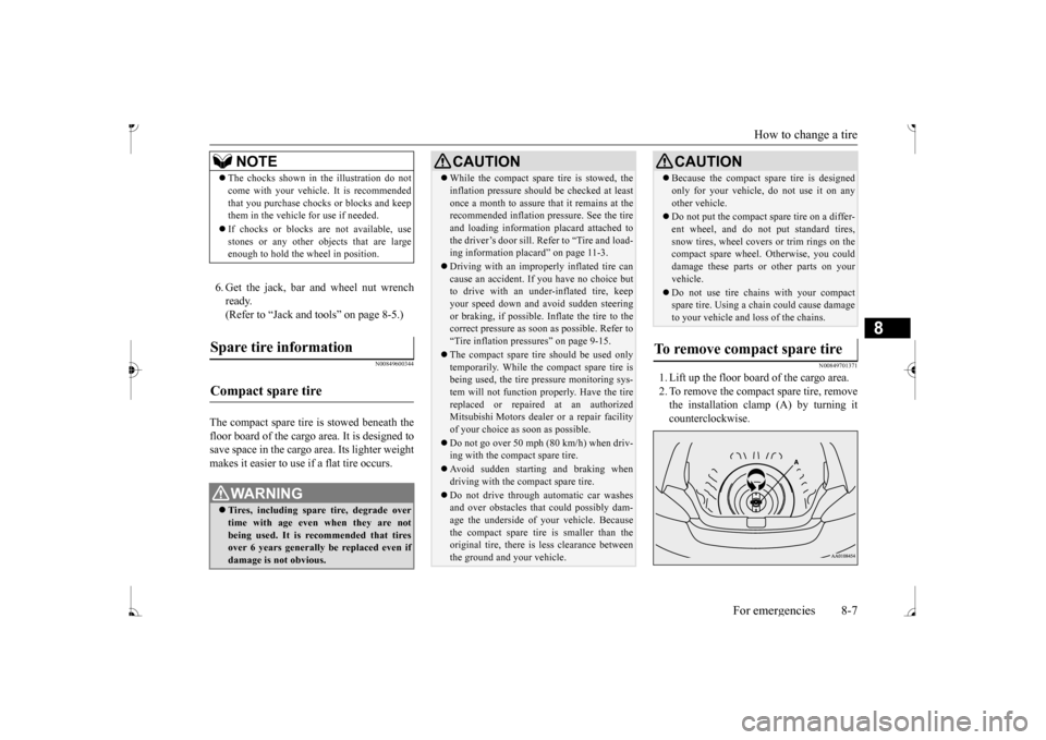
1. Lift up the floor board of the cargo area. 2. To remove the compact spare tire, remove the installation clamp (A) by turning itcounterclockwise.
NOTE
The chocks shown in the illustration do not come with your vehicl
e. It is recommended
that you purchase chocks or blocks and keepthem in the vehicle for use if needed. If chocks or blocks
are not available, use
stones or any other obj
ects that are large
enough to hold the wheel in position.
Spare tire information Compact spare tire
WA R N I N G Tires, including spar
e tire, degrade over
time with age even when they are notbeing used. It is recommended that tires over 6 years generally
be replaced even if
damage is not obvious.
CAUTION While the compact spare tire is stowed, the inflation pressure shoul
d be checked at least
once a month to assure that it remains at therecommended inflation pressure. See the tire and loading informati
on placard attached to
the driver’s door sill. Refer to “Tire and load-ing information placard” on page 11-3. Driving with an imprope
rly inflated tire can
cause an accident. If
you have no choice but
to drive with an under-inflated tire, keep your speed down and av
oid sudden steering
or braking, if possible. Inflate the tire to the correct pressure as soon as possible. Refer to “Tire inflation pressures” on page 9-15. The compact spare tire should be used only temporarily. While th
e compact spare tire is
being used, the tire pr
essure monitoring sys-
tem will not function
properly. Have the tire
replaced or repaired at an authorizedMitsubishi Motors dealer
or a repair facility
of your choice as soon as possible. Do not go over 50 mph (80 km/h) when driv- ing with the compact spare tire. Avoid sudden starting and braking when driving with the compact spare tire. Do not drive through automatic car washes and over obstacles that
could possibly dam-
age the underside of your vehicle. Becausethe compact spare tire is smaller than the original tire, there is less clearance between the ground and your vehicle.
Because the compact spare tire is designed only for your vehicle, do not use it on anyother vehicle. Do not put the compact spare tire on a differ- ent wheel, and do not put standard tires,snow tires, wheel covers
or trim rings on the
compact spare wheel. Otherwise, you could damage these parts or other parts on yourvehicle. Do not use tire chains with your compact spare tire. Using a chain could cause damage to your vehicle and loss of the chains.
To remove compact spare tire
CAUTION
BK0236100US.book 7 ページ 2016年2月1日 月曜日 午前10時15分
Page 249 of 307

How to change a tire 8-10 For emergencies
8
7. Install the wheel nuts with their tapered ends facing inward, then tighten by handuntil the wheel is no longer loose. 8. Lower the vehicle slowly until the tire touches the ground, by rotating the wheel nut wrench counterclockwise.
9. Tighten the nuts in the order shown in the illustration until each
nut has been tight-
ened to the torque listed here. 65 to 80 ft-lb (88 to 108 N•m)
10. Lower the jack all the way and remove it.
11. Check the tire inflation pressure. The rec-
ommended tire pressure for your vehicleis listed on the tire
and loading informa-
tion placard attached to the driver’s door sill as shown in the illustration. Refer to“Tire inflation pressures” on page 9-15.
CAUTION Never apply oil to either the wheel bolts or the nuts or they will tighten too much.
Steel wheel Aluminum wheel
CAUTION Never use your foot or a pipe extension to apply added force to the wheel nut wrench when tightening the wh
eel nuts. If you do so,
you can over-tighten the wheel nuts and damage the wheel, wheel nuts and hub bolts.
CAUTION Driving with an imprope
rly inflated tire can
cause an accident. If
you have no choice but
to drive with an under-inflated tire, keep your speed down and av
oid sudden steering
or braking, if possible. Inflate the tire to thecorrect pressure as soon as possible. Refer to “Tire inflation pressures” on page 9-15. After changing the tire
and driving the vehi-
cle about 620 miles (1,000 km), retighten the wheel nuts to make sure that they have notcome loose.
BK0236100US.book 10 ページ 2016年2月1日 月曜日 午前10時15分