2017 MERCEDES-BENZ SLC-Class trunk
[x] Cancel search: trunkPage 221 of 294

XTo turn over:lift reversible floor panel ;
using tab :.
XTurn overand then re-inser treversible floor
panel ;.
Twoflexible straps ;are attachedtot he rever-
sibl efloor panel ,use thes etos ecure objects,
such as wind screen =,whenr eversibl efloor
panel :hasb eent urne dover.
Roo fcarrier
!
Thi svehicl eisn ot designed to transport
items on the roof. Roof carriers and other
device swhich are mounted on the roo fthat
have not been specifically approved for this
model by Mercedes-Benz must not be used as
they could damag ethe vehicl eand the
retractable hardto p(vario-roof).
At the time of going to print, Mercedes-Benz
does not offe rany roo fcarrie roro therroof-
installe ddevice sfor thism odel.
!Thisvehicl eisn ot designed to transport any
items on the trunk li dortoallowluggage car-
riers or equipment of any kind to be installed
to the trunk lid. Otherwise the vehicl eand the
retractable hardto pcould be damaged.
Features
Cup holder
Important safety notes
GWARNING
If objects in the passenger compartment are
stowed incorrectly ,they can slid eorbe
thrown around and hitv ehicleoccupants. In
addition, cupholders, open stowag espaces
and mobil ephone brackets canno talway s
retain al lobjects they contain. There is arisk
of injury,p articularly in the event of sudden
braking or asudde nchange in direction.
RAlway sstow objects so thatt hey cannotbe
thrown around in such situations.
RAlway smakes uret hato bjects do not pro-
trud efrom stowag espaces, parcel nets or
stowag enets.
RClose the lockable stowag espaces before
starting ajourney.
RAlway sstow and secure heavy,h ard, poin-
ted,s harp-edged ,fragile or bulky objects in
the trunk.
!Onlyu sethe cup holders for containers of
the right size and which have lids. The drinks
could otherwise spill.
!Do not expose drinks bottle sinthe cup
holde rinthe cente rconsole to continuous,
strong and direct sunlight. The passenger
compartment in the are aofthe cente rcon-
sol ec an otherwise be damaged by the con-
centrated and reflecte dsunlight.
Cup holder in the centerc onsole
Features219
Stowageand featur es
Z
Page 232 of 294

Calibratingthe compass
XMakes ure that there is sufficient spacef or
you to driv einacircle without impedingt raf-
fic.
In order to calibrat ethe compass correctly, do
th ef ollowing:
Rcalibrat ethe compass in th eopen and no tin
th ev icinity of steel structures or high-voltage
transmission lines.
Rswitch off electrical consumers suchast he
climate control, windshield wipersorr ear win-
dow defroster.
Rclose all doorsa nd thetrunk lid.
XSwitch on th eignition.
XPush aroun dpen int oopening =
(Ypage 229) for approximately six seconds,
until symbol Cis shown in compass display ;
(Ypage 229).
XDrive your vehicle in afull circle at approx-
imately 3mph (5 km/h )to6mph (10 km/h).
When th ecalibration has successfully been
completed, th ecurren tdirection is shown in
compass display ;(
Ypage 229).
Floormats
GWARNING
Object sinthedriver'sf ootwell can restrict the
pedal travel or obstruc tadepressed pedal.
The operatin gand road safety of th evehicle is
jeopardized. Thereisar iskofana ccident.
Makes ure that all object sinthevehicle are
stowed correctly, and that they canno tenter
th ed river'sf ootwell. Install th efloormats
securely and as specifie dinorder to ensure
sufficient clearance for th epedals.Don otuse
loosef loormats and do no tplacef loormats on
to pofo neanother.
XSlid ethe seat backwards.
XTo install: placethefloormat in th efootwell.
XPress studs :onto retainers ;.
XTo remove:pull thefloormat off retainers ;.
XRemove thefloormat.
230Features
Stowage and features
Page 243 of 294

Where willIfind...?
Vehicle tool kit
General notes
The vehicl etool kit can be found in the trunk or
in the stowage wel lunder the trunk floor.
Apart from certain country-specifi cvariations,
the vehicles are not equipped with atire-change
tool kit. Some tools for changing awheela re
specific to the vehicle. For more information on
which tools are required to perform awheel
change on you rvehicle, consul taqualified spe-
cialist workshop.
Necessary tire-changing tools can include, for
example:
RJack
RWheelc hock
RLug wrench
RRatchet wrench
RAlignment bolt
Vehicles with aTIREFIT kit
:Tire sealant filler bottle
;Fuse allocatio nchart
=Tire inflation compressor
?Towing eye
XLift the trunk floor up.
XUse the TIREFIT kit (Ypag e243).
iExample :equipment and country-specific
variations possible.
Vehicles with acollapsible spare wheel
The collapsible spare wheel can be found in the
stowage wel lunder the trunk floor (Ypag e218).
:Folding wheel chock
;Fuse allocatio nchart
=Jack
?Sheet for faulty wheel
AAlignment bolt
BLug wrench
CTowing eye
DValve extractor
ETire inflation compressor
XRemove the collapsible spare wheel
(Ypag e280).
Flat tire
Preparing the vehicle
You rvehiclem ay be equipped with:
Rtires with run-fla tcharacteristics
(MOExtended tires) (Ypag e242)
Vehicle preparation is not necessary on vehi-
cles with MOExtended tires
Ran emergency spare wheel (Ypag e279)
Vehicles equipped with MOExtended tires are
not equipped with aTIREFIT kit at the factory.I t
is therefore recommendedt hat you additionally
equip you rvehicl ewithaTIREFIT kit if you mount
tires that do not feature run-fla tproperties, e.g.
winter tires. ATIREFIT kit may be obtained from
aq ualified specialist workshop.
Informatio nonchanging and mounting wheels
(
Ypag e274).
XStop the vehicl eonsolid, non-slippery and
leve lground, as far away as possible from
traffic.
XSwitch on the hazard warning lamps.
XSecure the vehicl eagainst rolling away
(Ypag e131).
Flat tire241
Breakdown assistance
Page 245 of 294

Ryou see smokeand smell rubber.
RESP®is intervenin gconstantly .
Rthere are tears in th esidewalls of th etire.
Afte rdrivin gine mergenc ymode, hav ethe
whee lrim sc hecked ataq ualified specialist
workshop wit hregard to their further use. The
defective tire mus tbereplaced in every case.
TIREFIT kit
Impor tant safety notes
TIREFITisat ires ealant .
You can use TIREFI Ttoseal punctures of up to
0.16 in (4 mm), particularly those in th etire
tread. You can use TIREFI Tatoutside tempera-
tures down to Ò4‡(Ò20 †).
GWARNIN G
In th efollowin gsituations, th etires ealant is
unable to provid esufficien tbreakdown assis-
tance ,asitisu nable to seal th etirep roperly:
Rthere are cut sorpunctures in th etirel arger
than those mentioned above.
Rth ew hee lrim is damaged.
Ryou hav edriven at ver ylow tire pressures or
on aflat tire.
There is ariskofana ccident.
Do no tdrive th evehicle. Contac taqualified
specialist workshop .
GWARNING
The tire sealant is harmful and causes irrita-
tion .Itm ustn otcome into contact wit hyour
skin ,eyes or clothin gorbeswallowed .Donot
inhale TIREFI Tfumes. Kee ptires ealant away
from children .There is ariskofi njury.
If you come into contact wit hthe tire sealant ,
observ ethe following:
RRinse off th etires ealant from your skin
immediately wit hwater.
RIf th etires ealant comes into contact wit h
your eyes ,immediately rinse them thor-
oughly wit hclean water.
RIf tire sealant is swallowed ,immediately
rinse your mout hout thoroughl yand drink
plenty of water. Do no tind ucev omiting,
and see kmedica lattention immediately.
RImmediately chang eout of clothin gwhich
has come into contact wit htires ealant .
RIf an allergic reaction occurs, see kmedica l
attention immediately.
!Do no toperate th etirei nflation compressor
for longer than eigh tminute satat imew ithout
ab reak. It may otherwise overheat.
The tire inflation compressor can be operate d
again once it has cooled down .
Comply wit hthe manufacturer’s safet yinstruc-
tion sont hesticker on th etirei nflation com-
pressor.
Usingt heTIREFIT kit
XDo no tremove any foreign objects whic hhave
penetrated th etire, e.g. screw sornails.
XRemove th etires ealant bottle, th eaccompa-
nying TIREFI Tsticker and th etirei nflation
compressor from th estowage well under-
neath th etrunk floor (
Ypage 241).
XAffix part :of th eTIREFI Tsticker to th e
instrumen tcluste rwithin th edriver's field of
vision .
XAffix part ;of th eTIREFI Tsticker near th e
valv eont hewhee lwitht he defective tire.
Flat tire243
Breakdown assis tance
Z
Page 255 of 294

!Vehicles with automatic transmission must
not be towed with the rear axle raised. The
vehicle/trailer combination may otherwise
swerve or even roll over.
Transporting the vehicle
Vehiclesw ith automatic transmission
!When the vehicle is loadedf or transport, the
front and rear axles must be stationary and on
the same transportation vehicle. Positioning
over the connection point of the transport
vehicle is not permitted. The drive train may
otherwise be damaged.
All vehicles
!You may only secure the vehicle by the
wheels, not by parts of the vehicle such as
axle or steering components. Otherwise, the
vehicle could be damaged.
The towing eye can be used to pull the vehicle
onto atrailer or transporter for transporting pur-
poses.
XTurn the SmartKey to position 2in the ignition
lock.
XShift the transmission to position N.
As soon as the vehicleh as been loaded:
XPrevent the vehicle from rolling awayb y
applying the electric parking brake.
XShift the transmission to position P.
XTurn the SmartKey in the ignition lock to posi-
tion0and remove the SmartKey from the
ignition lock.
XSecure the vehicle.
Tow-starting (emergencye ngine
starting)
!
Vehicles with automatic transmission must
not be tow-started. You could otherwise dam-
age the automatic transmission.
You can find information on "Jump-starting" at
(
Ypage 249).
Fuses
Important safety notes
GWARNING
If you manipulate or bridge afaulty fuse or if
you replace it with afuse with ahigher amper-
age, the electric cables could be overloaded.
This could result in afire. There is arisk of an
accident and injury.
Alwaysr eplace faulty fuses with the specified
new fuses having the correct amperage.
Blown fuses must be replaced with fuses of the
same rating, which you can recognize by the
color and value.T he fuse ratings are listed in the
fuse allocation chart.
The fuse allocation chart is located in the vehicle
tool kit in the stowage compartment under the
trunk floor (
Ypage 241).
If an ewly inserted fuse also blows, have the
cause traced and rectified at aqualified special-
ist workshop, e.g. an authorized Mercedes-Benz
Center.
!Only use fuses that have been approved for
Mercedes-Benz vehicles and which have the
correct fuse rating for the system concerned.
Otherwise, componentsors ystems could be
damaged.
!Make sure that no moisture can enter the
fuse box when the cover is open.
!When closing the cover, make sure that it is
lying correctly on the fuse box. Moisture seep-
ing in or dirt could otherwise impair the oper-
ation of the fuses.
The fuses in your vehicle serve to close down
faulty circuits. If afuse blows, all the compo-
nentsont he circuit and their functions stop
operating.
Fuses253
Breakdown assistance
Z
Page 256 of 294

Before changingafuse
XSwitch off the engine.
XSwitch off al lelectrical consumers.
XMake sure thatt he ignition is switched off
(Ypage 115).
or
XWhe nusing the SmartKey, turn the SmartKey
to position 0in the ignition lock and remove it
(
Ypage 115).
XSecure the vehicl eagain st rolling away
(Ypage 131).
All indicator lamps in the instrument cluster
must be off.
The fuses are locate dinvarious fus eboxes:
RFus eboxin the engine compartment on the
left-hand side of the vehicle, when viewe din
the direction of travel
RFus eboxin the trunk
Fuse bo xinthe engine compartment
i
Observ ethe "Important safety notes "sec-
tio n(Ypage 253).
GWARNING
Whe nthe hoo disopena nd the windshield
wipers are set in motion, yo ucan be injured by
the wipe rlinkage. There is ariskofi njury.
Alway sswitch off the windshield wipers and
the ignition before opening the hood.
XMake sure thatt he windshield wipers are
turne doff.
XOpe nthe hood.
XUse adry cloth to remove any moisture from
the fus ebox.
XTo open: open clamps ;.
XRemove fuseboxcover :forwards.
XTo close: check whethe rthe sea lislying cor-
rectl yinc over:.
XInsert cover :at the rea rofthe fus eboxinto
the retainer.
XFol dd ownc over :and close clamps ;.
XClose the hood.
Fuse boxinthe trunk
i
Observ ethe "Important safety notes "sec-
tio n(Ypage 253).
The fus eboxis locate dinthe trunk behind the
partition covering.
XOpe nthe trunk lid.
XTo open: release cover :on the right and
left-hand side swithaf lato bject.
XOpe ncover :downward sinthe direction of
the arrow.
254Fuses
Breakdo wn assis tance
Page 278 of 294

must be positioned vertically, directly under
the jacking point of the vehicle.
!The jack is designed exclusively for jacking
up the vehicleatt he jacking points. Other-
wise ,you rv ehiclec ould be damaged.
Observe the following when raising the vehicle:
RTo rais ethe vehicle, only use the vehicle-spe-
cific jack that has been tested and approved
by Mercedes-Benz. If used incorrectly, the
jack could tip over with the vehicler aised.
RThe jack is designed only to raiseand hold the
vehiclef oras hort time while awheelisb eing
changed. It must not be used for performing
maintenance work under the vehicle.
RAvoid changing the whee lonuphill and down-
hill slopes.
RBefore raising the vehicle, secure it from roll-
ing awa ybyapplying the parking brake and
inserting whee lchocks. Do not disengage the
parking brake whil ethe vehicleisr aised.
RThe jack must be placed on afirm, flat and
non-slip surface. On aloose surface, alarge,
flat, load-bearing underlay must be used .Ona
slippery surface, anon-slip underlay must be
used ,e.g. rubber mats.
RDo not use wooden blocks or similar objects
as ajack underlay.O therwise, the jack wil lnot
be abl etoachieve its load-bearing capacity
due to the restricted height.
RMake sure that the distance betwee nthe
underside of the tires and the ground does not
exceed 1.2 in (3 cm).
RNever place you rhands and feet under the
raised vehicle.
RDo not lie under the vehicle.
RDo not start the engine when the vehiclei s
raised.
RDo not open or close adoor or the trunk lid
when the vehicleisr aised.
RMake sure that no persons are present in the
vehiclewhen the vehicleisr aised.
XUsing lug wrench:,loosent he bolts on the
whee lyou wish to change by abou tone full
turn. Do not unscrew the bolts completely.
The jacking points are located just behind the
front whee lhousings and just in front of the rear
whee lhousings (arrows).
Vehicles with AMG equipment: the vehicle
has covers installed to protect the vehicleb ody
next to the jacking points on the outer sills.
XFold cover ;upwards.
276Changing awheel
Wheel sand tires
Page 282 of 294
Snow chains mustnot be mounted on emer-
gency spare wheels.
General notes
You can as kfor information regarding permitted
emergency spare wheel satanauthorized
Mercedes-Benz Center.
You shoul dregularl ycheck the pressure of the
emergency spare wheel ,particularly prior to
long trips, and correct the pressure as neces-
sary (
Ypage 258). The value on the wheel is
valid.
An emergency spare wheel may also be moun-
ted against the direction of rotation. Observe
the time restriction on us easwellast he speed
limitation specified on the emergency spare
wheel.
Replace the tire saftersix years at the latest,
regardless of wear. Thi salsoa pplies to the
emergency spare wheel.
Whe nyou are driving with the collapsibl espare
wheel mounted, the tire pressure loss warning
system or the tire pressure monitor canno tfunc-
tion reliably. Only restart the tire pressure loss
warning system or tire pressure monitor when
the defectiv ewheel hasb eenr eplaced with a
new wheel.
Vehicles with tire pressure monitor: after
mounting an emergency spare wheel ,the sys-
tem may stil ldisplay the tire pressure of the
removed wheel for afew minutes. The value dis-
played for the mounted emergency spare wheel
is not the same as the current tire pressure of
the emergency spare wheel.
Removin gthe emergencys pare wheel
Collapsibles pare wheel unde rthe trunk
floor
The collapsibl espare wheel can be found in the
stowag ewellu nder the trunk floor (Ypage 218).
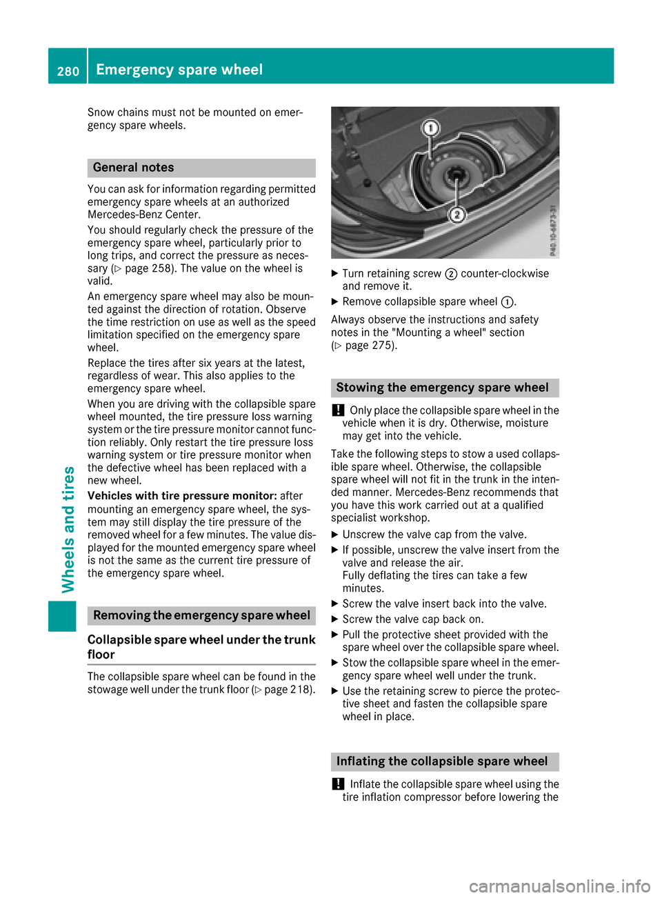
XTurn retaining screw ;counter-clockwise
and remove it.
XRemove collapsibl espare wheel :.
Alway sobserve the instructions and safety
notes in the "Mounting awheel"s ection
(
Ypage 275).
Stowin gthe emergencys pare wheel
!
Only place the collapsibl espare wheel in the
vehicl ewhenitisd ry.O therwise, moisture
may get into the vehicle.
Take the following step stostowausedc ollaps-
ible spare wheel .Otherwise, the collapsible
spare wheel will not fit in the trunk in the inten-
ded manner. Mercedes-Benz recommend sthat
yo uh avet his work carrie doutataq uali fied
specialist workshop.
XUnscrewt he valve cap from the valve.
XIf possible ,unscrew the valve insert from the
valve and release the air.
Fully deflating the tire scan take afew
minutes.
XScrew the valve insert back into the valve.
XScrew the valve cap back on.
XPull the protectiv esheet provided with the
spare wheel ove rthe collapsibl espare wheel.
XStow the collapsibl espare wheel in the emer-
gency spare wheel well under the trunk.
XUse the retaining screwtop ierce the protec-
tive sheet and fasten the collapsibl espare
wheel in place.
Inflating the collapsibles pare wheel
!
Inflate the collapsibl espare wheel using the
tire inflation compressor before lowering the
280Emergencys pare wheel
Wheels and tires