2017 MERCEDES-BENZ S-Class COUPE ECU
[x] Cancel search: ECUPage 313 of 338

XPress0063or0064 to select Tire Pres‐sure.
XPress the 0076button.
The current tire pressure of each tire is shown
in the multifunction display.
If the vehicle was parked for longer than
20 minutes, the following message appears:
Tire
pressurewillbedisplayedafterdriving a few minutes.
After a teach-in process, the tire pressure mon-
itor automatically detects new wheels or new
sensors. As long as a clear allocation of the tire
pressure value to the individual wheels is not
possible, the Tire
PressureMonitorActivemessage is shown instead of the tire pressure
display. The tire pressures are already being
monitored.
Tire pressure monitor warning mes-
sages
If the tire pressure monitor detects a pressure
loss in one or more tires, a warning message is
shown in the multifunction display. The yellow
tire pressure warning lamp then lights up.
RIf thePlease Correct Tire Pressuremessage appears in the multifunction display,
the tire pressure in at least one tire is too low.
The tire pressure must be corrected when the opportunity arises.
RIf the Check Tiresmessage appears in the
multifunction display, the tire pressure in at
least one tire has dropped significantly. The
tires must be checked.
RIf the WarningTireMalfunctionmessage
appears in the multifunction display, the tire
pressure in at least one tire has dropped sud-
denly. The tires must be checked.
Observe the instructions and safety notes in the
display messages in the "Tires" section
(
Ypage 226).
If the wheel positions on the vehicle are rotated, the tire pressures may be displayed for the
wrong positions for a short time. This is rectified
after a few minutes of driving, and the tire pres-
sures are displayed for the correct positions.
Restarting the tire pressure monitor
When you restart the tire pressure monitor, all
existing warning messages are deleted and the
warning lamps go out. The monitor uses the cur-
rently set tire pressure as the reference values for monitoring. In most cases, the tire pressure
monitor will automatically detect the new refer-
ence values after you have changed the tire
pressure. However, you can also set reference
values manually as described here. The tire
pressure monitor then monitors the new tire
pressure values.
XSet the tire pressure to the value recommen-
ded for the corresponding driving situation on
the Tire and Loading Information placard on
the driver's side B-pillar (
Ypage 306).
You can find more tire pressure values for
various operating conditions in the tire pres-
sure table inside the fuel filler flap
(
Ypage 306).
XMake sure that the tire pressure is correct on
all four wheels.
XMake sure that the SmartKey is in position 2
in the ignition lock.
XUse 00E2 on the steering wheel to call up the
list of menus.
XPress 0063or0064 on the steering wheel to
select the Servicemenu.
XPress the0076button.
XPress 0063or0064 to select Tire Pres‐sure.
XPress the 0076button.
The current tire pressure for each wheel or
the Tire pressure will be displayed
after driving a few minutesmessage
will be displayed in the multifunction display.
XPress the 0064button.
The UseCurrentPressuresasNewRef‐erenceValuesmessage appears in the mul-
tifunction display.
If you wish to confirm the restart:
XPress the 0076button.
The TirePress.MonitorRestartedmes-
sage appears in the multifunction display.
After driving for a few minutes, the system
checks whether the current tire pressures are
within the specified range. The new tire pres-
sures are then accepted as reference values
and monitored.
If you wish to cancel the restart:
XPress the 0038button.
The tire pressure values stored at the last
restart will continue to be monitored.
Tire pressure311
Wheels and tires
Z
Page 323 of 338

Tire pressure
This is pressure inside the tire applying an out-
ward force to each square inch of the tire's sur-
face. The tire pressure is specified in pounds per
square inch (psi), in kilopascal (kPa) or in bar.
The tire pressure should only be corrected whenthe tires are cold.
Cold tire pressure
The tires are cold:
Rif the vehicle has been parked with the tires
out of direct sunlight for at least three hours
and
Rif the vehicle has not been driven further than
1 mile (1.6 km)
Tread
The part of the tire that comes into contact with
the road.
Bead
The tire bead ensures that the tire sits securely
on the wheel. There are several steel wires in the
bead to prevent the tire from coming loose from
the wheel rim.
Sidewall
The part of the tire between the tread and the
bead.
Weight of optional extras
The combined weight of those optional extras
that weigh more than the replaced standard
parts and more than 5 lbs (2.3 kg). These
optional extras, such as high-performance
brakes, level control, a roof rack or a high-per-
formance battery, are not included in the curb
weight and the weight of the accessories.
TIN (Tire Identification Number)
This is a unique identifier which can be used by
a tire manufacturer to identify tires, for example
for a product recall, and thus identify the pur-
chasers. The TIN is made up of the manufactur- er's identity code, tire size, tire type code and
the manufacturing date.
Load bearing index
The load bearing index (also load index) is a code
that contains the maximum load bearing capa-
city of a tire.
Traction
Traction is the result of friction between the tires
and the road surface.
Treadwear indicators
Narrow bars (tread wear bars) that are distrib-
uted over the tire tread. If the tire tread is level
with the bars, the wear limit of 00CDin (1.6 mm)
has been reached.
Occupant distribution
The distribution of occupants in a vehicle at their
designated seating positions.
Total load limit
Nominal load and luggage load plus 68 kg
(150 lbs) multiplied by the number of seats in
the vehicle.
Changing a wheel
Flat tire
The "Breakdown assistance" section
(Ypage 288 )contains information and notes on
how to deal with a flat tire. Information on driv-
ing with MOExtended tires in the event of a flat
tire can be found under "MOExtended tires (tires
with run-flat characteristics" (
Ypage 289).
Rotating the wheels
GWARNING
Interchanging the front and rear wheels may
severely impair the driving characteristics if
the wheels or tires have different dimensions. The wheel brakes or suspension components
may also be damaged. There is a risk of acci-
dent.
Rotate front and rear wheels only if the wheels and tires are of the same dimensions.
!On vehicles equipped with a tire pressure
monitor, electronic components are located
in the wheel.
Tire-mounting tools should not be used near
the valve. This could damage the electronic
components.
Only have tires changed at a qualified spe-
cialist workshop.
Changing a wheel321
Wheels and tires
Z
Page 324 of 338

Always observe the instructions and safety
notes in the "Mounting a wheel" section
(
Ypage 322).
The wear patterns on the front and rear tires
differ, depending on the operating conditions.
Rotate the wheels before a clear wear pattern
has formed on the tires. Front tires typically
wear more on the shoulders and the rear tires in the center.
On vehicles that have the same size front and
rear wheels, you can rotate the wheels accord-
ing to the intervals in the tire manufacturer's
warranty book in your vehicle documents. If no
warranty book is available, the tires should be
rotate every 3,000 to 6,000 miles(5,00 0 to
10,000 km). Earlier may be necessary, depend-
ing on the degree of tire wear. Do not change the
direction of wheel rotation.
Clean the contact surfaces of the wheel and the
brake disc thoroughly every time a wheel is rota- ted. Check the tire pressure and reactivate the
tire pressure monitor if necessary (
Ypage 311).
Direction of rotation
Tires with a specified direction of rotation have
additional benefits, e.g. if there is a risk of hydro-
planing. These advantages can only be gained if
the tires are installed corresponding to the
direction of rotation.
An arrow on the sidewall of the tire indicates its
correct direction of rotation.
Storing wheels
Store wheels that are not being used in a cool,
dry and preferably dark place. Protect the tires
from oil, grease, gasoline and diesel.
Mounting a wheel
Preparing the vehicle
XStop the vehicle on solid, non-slippery and
level ground.
XApply the electric parking brake manually.
XBring the front wheels into the straight-ahead position.
XShift the transmission to position P.
XMake sure that the vehicle level is set to "Nor-
mal" for AIRMATIC (Ypage 158) or Active
Body Control (ABC) (Ypage 156).
XSwitch off the engine.
XOpen the driver's door.
The vehicle electronics now have status 0.
This is the same as the SmartKey having been
removed.
XRemove Start/Stop button from ignition lock
(Ypage 121).
or, if the SmartKey is inserted in the ignition
lock:
XRemove the SmartKey from the ignition lock.
XMake sure that the engine cannot be started
via your smartphone (Ypage 123).
XIf included in the vehicle equipment, remove
the tire-change tool kit from the vehicle.
XSafeguard the vehicle against rolling away.
Securing the vehicle to prevent it from
rolling away
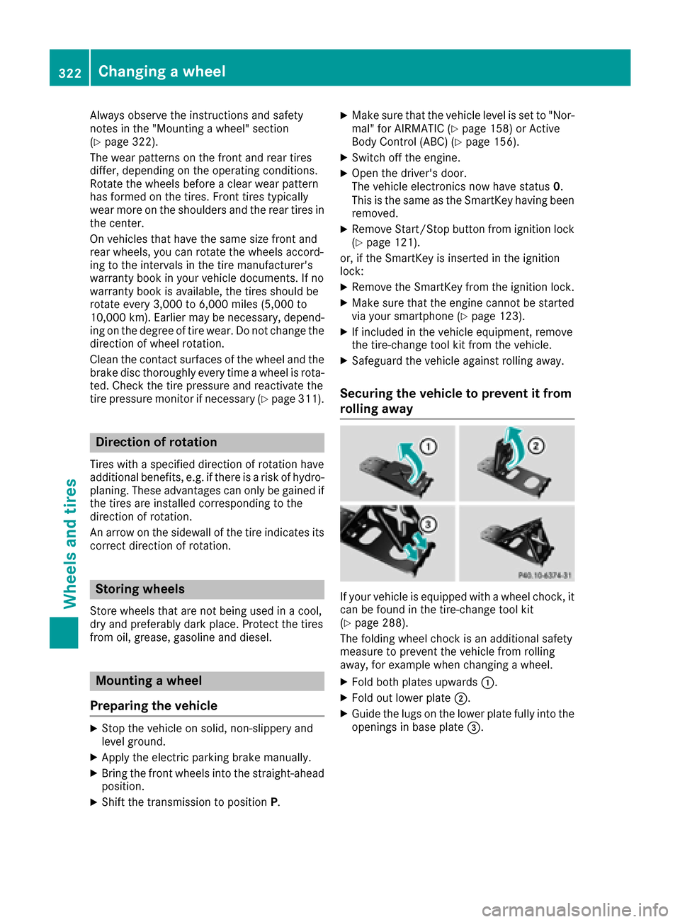
If your vehicle is equipped with a wheel chock, it can be found in the tire-change tool kit
(
Ypage 288).
The folding wheel chock is an additional safety
measure to prevent the vehicle from rolling
away, for example when changing a wheel.
XFold both plates upwards 0043.
XFold out lower plate0044.
XGuide the lugs on the lower plate fully into the
openings in base plate 0087.
322Changing awheel
Wheels an d tires
Page 325 of 338

XPlace chocks or other suitable items under
the front and rear of the wheel that is diago-
nally opposite the wheel you wish to change.
Raising the vehicle
GWARNING
If you do not position the jack correctly at the
appropriate jacking point of the vehicle, the
jack could tip over with the vehicle raised.
There is a risk of injury.
Only position the jack at the appropriate jack-
ing point of the vehicle. The base of the jack
must be positioned vertically, directly under
the jacking point of the vehicle.
!The jack is designed exclusively for jacking
up the vehicle at the jacking points. Other-
wise, your vehicle could be damaged.
Observe the following when raising the vehi-
cle:
RTo raise the vehicle, only use the vehicle-spe-
cific jack that has been tested and approved
by Mercedes-Benz. If used incorrectly, the
jack could tip over with the vehicle raised.
RThe jack is designed only to raise and hold the
vehicle for a short time while a wheel is being
changed. It must not be used for performing
maintenance work under the vehicle.
RAvoid changing the wheel on uphill and down-
hill slopes.
RBefore raising the vehicle, secure it from roll-
ing away by applying the parking brake and
inserting wheel chocks. Do not disengage the
parking brake while the vehicle is raised.
RThe jack must be placed on a firm, flat and
non-slip surface. On a loose surface, a large,
flat, load-bearing underlay must be used. On a slippery surface, a non-slip underlay must be
used, e.g. rubber mats.
RDo not use wooden blocks or similar objects
as a jack underlay. Otherwise, the jack will not
be able to achieve its load-bearing capacity
due to the restricted height.
RMake sure that the distance between the
underside of the tires and the ground does not
exceed 1.2 in (3 cm).
RDo not place your hands or feet under the
raised vehicle.
RDo not lie under the vehicle.
RDo not start the engine when the vehicle is
raised.
RDo not open or close a door or the trunk lid
when the vehicle is raised.
RMake sure that no persons are present in the
vehicle when the vehicle is raised.
Vehicles with AMG wheels and hub caps: the
hub cap covers the wheel bolts. Before you can
unscrew the wheel bolts, you must remove the
hub cap. Two different variant
s can be installed.
Vehicles with AMG wheels and plastic hub
caps:
XTo remove: turn the center cover of hub
cap 0043counter-clockwise and remove.
XTo install: before installing, ensure that hub
cap 0043is in the open position. To do this, turn
the center cover counter-clockwise.
XPosition hub cap 0043and turn the center cover
clockwise until hub cap 0043engages physically
and audibly.
XMake sure that hub cap 0043is installed
securely.
Changing a wheel323
Wheels and tires
Z
Page 327 of 338

Removing a wheel
!Mercedes-AMG vehicles:during removal
and repositioning of the wheel, the wheel rim
can strike the ceramic-brake disc and dam-
age it. Therefore, you should proceed care-
fully and get a second person assist to you.
Alternatively, you can use a second alignment
bolt.
!Do not place wheel bolts in sand or on a dirty
surface. The bolt and wheel hub threads could
otherwise be damaged when you screw them
in.
When mounting/removing wheels, and for as
long as the wheels are removed, avoid applying
any external force on the brake disks. This could
impair the level of comfort when braking.
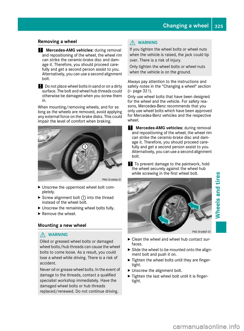
XUnscrew the uppermost wheel bolt com-
pletely.
XScrew alignment bolt 0043into the thread
instead of the wheel bolt.
XUnscrew the remaining wheel bolts fully.
XRemove the wheel.
Mounting a new wheel
GWARNING
Oiled or greased wheel bolts or damaged
wheel bolts/hub threads can cause the wheel bolts to come loose. As a result, you could
lose a wheel while driving. There is a risk of
accident.
Never oil or grease wheel bolts. In the event of
damage to the threads, contact a qualified
specialist workshop immediately. Have the
damaged wheel bolts or hub threads
replaced/renewed. Do not continue driving.
GWARNING
If you tighten the wheel bolts or wheel nuts
when the vehicle is raised, the jack could tip
over. There is a risk of injury.
Only tighten the wheel bolts or wheel nuts
when the vehicle is on the ground.
Always pay attention to the instructions and
safety notes in the "Changing a wheel" section
(
Ypage 321).
Only use wheel bolts that have been designed
for the wheel and the vehicle. For safety rea-
sons, Mercedes-Benz recommends that you
only use wheel bolts which have been approved for Mercedes-Benz vehicles and the respective
wheel.
!Mercedes-AMG vehicles: during removal
and repositioning of the wheel, the wheel rim
can strike the ceramic-brake disc and dam-
age it. Therefore, you should proceed care-
fully and get a second person assist to you.
Alternatively, you can use a second alignment
bolt.
!To prevent damage to the paintwork, hold
the wheel securely against the wheel hub
while screwing in the first wheel bolt.
XClean the wheel and wheel hub contact sur-
faces.
XSlide the wheel to be mounted onto the align-
ment bolt and push it on.
XTighten the wheel bolts until they are finger-
tight.
XUnscrew the alignment bolt.
XTighten the last wheel bolt until it is finger-
tight.
Changing a wheel325
Wheels and tires
Z