2017 MERCEDES-BENZ GLE43AMG SUV door lock
[x] Cancel search: door lockPage 174 of 366
cle could rollover more easily, for example on
a bend. There is a risk of an accident.
Always select as low a vehicle level as possi-
ble and adjust your driving style.
GWARNING
When you drive with the chassis lowered or
raised, the vehicle's braking and driving char-
acteristics can be significantly impaired. You
could also exceed the permissible vehicle
height if the chassis is raised. There is a risk of an accident.
Adjust the vehicle level before pulling away.
GWARNING
Due to the high center of gravity, the vehicle
may start to skid and roll over in the event of
an abrupt steering maneuver and/or when
the vehicle's speed is not adapted to the road
conditions. There is a risk of an accident.
Always adapt your speed and driving style to
the vehicle's driving characteristics and to the
prevailing road and weather conditions.
!When driving on extremely rough terrain,
select a high vehicle level in good time. Make
sure there is always sufficient ground clear-
ance. You will otherwise damage the vehicle.
RUtility vehicles have a significantly higher roll- over rate than other types of vehicles.
Failure to operate this vehicle safely may
result in an accident, rollover of the vehicle,
and severe or fatal injury.
RIn a rollover crash, an unbelted person is sig-
nificantly more likely to die than a person
wearing a seat belt.
You and all vehicle occupants should always
wear your seat belts.
General notes
Only select raised level if this is appropriate for
the road conditions. Otherwise, fuel consump-
tion may increase and handling may be affected.
Make changes to the vehicle level while the
vehicle is in motion. This enables the vehicle to
adjust to the new level as quickly as possible.
The vehicle level may change visibly if you park
the vehicl
e and the outside temperature
changes. If the temperature drops, the vehicle level is lower; with an increase in temperature,
the vehicle level rises.
If you unlock the vehicle or open a door, the
vehicle begins to compensate for load discrep-
ancies while still parked. However, for signifi-
cant level changes, such as after the vehicle has
been stationary for a long period, the engine
must be on. For safety reasons, the vehicle is
only lowered when the doors are closed. Low-
ering is interrupted if a door is opened, and it
continues once the door has been closed.
Vehicles with no trailer coupled:
below a
speed of 40 mph (64 km/h), you can choose
between the normal and raised vehicle level.
Select the normal vehicle level for normal road
surfaces and the raised vehicle level for driving
with snow chains or on particularly poor road
surfaces. Your selection remains stored even if
you remove the SmartKey from the ignition lock.
If you try to select raised level at a speed above
40 mph (64 km/h), the Drive More Slowly
message appears in the multifunction display.
Vehicles with a trailer coupled: below a speed
of 19 mph (30 km/h), you can choose between
the normal and raised vehicle level.
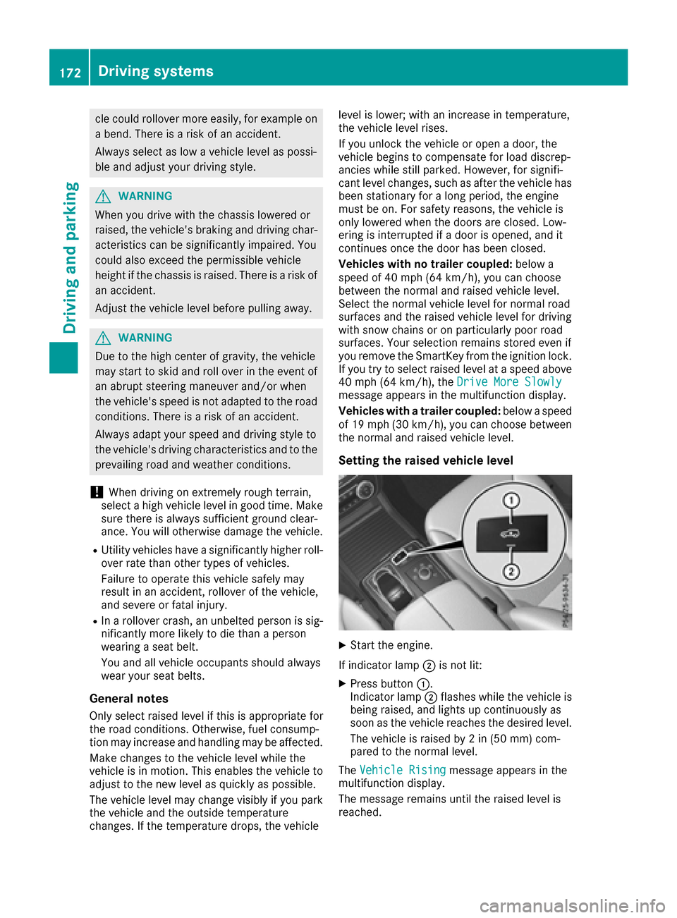
Setting the raised vehicle level
XStart the engine.
If indicator lamp ;is not lit:
XPress button :.
Indicator lamp ;flashes while the vehicle is
being raised, and lights up continuously as
soon as the vehicle reaches the desired level.
The vehicle is raised by 2 in (50 mm) com-
pared to the normal level.
The Vehicle Rising
message appears in the
multifunction display.
The message remains until the raised level is
reached.
172Driving systems
Driving and parking
Page 204 of 366
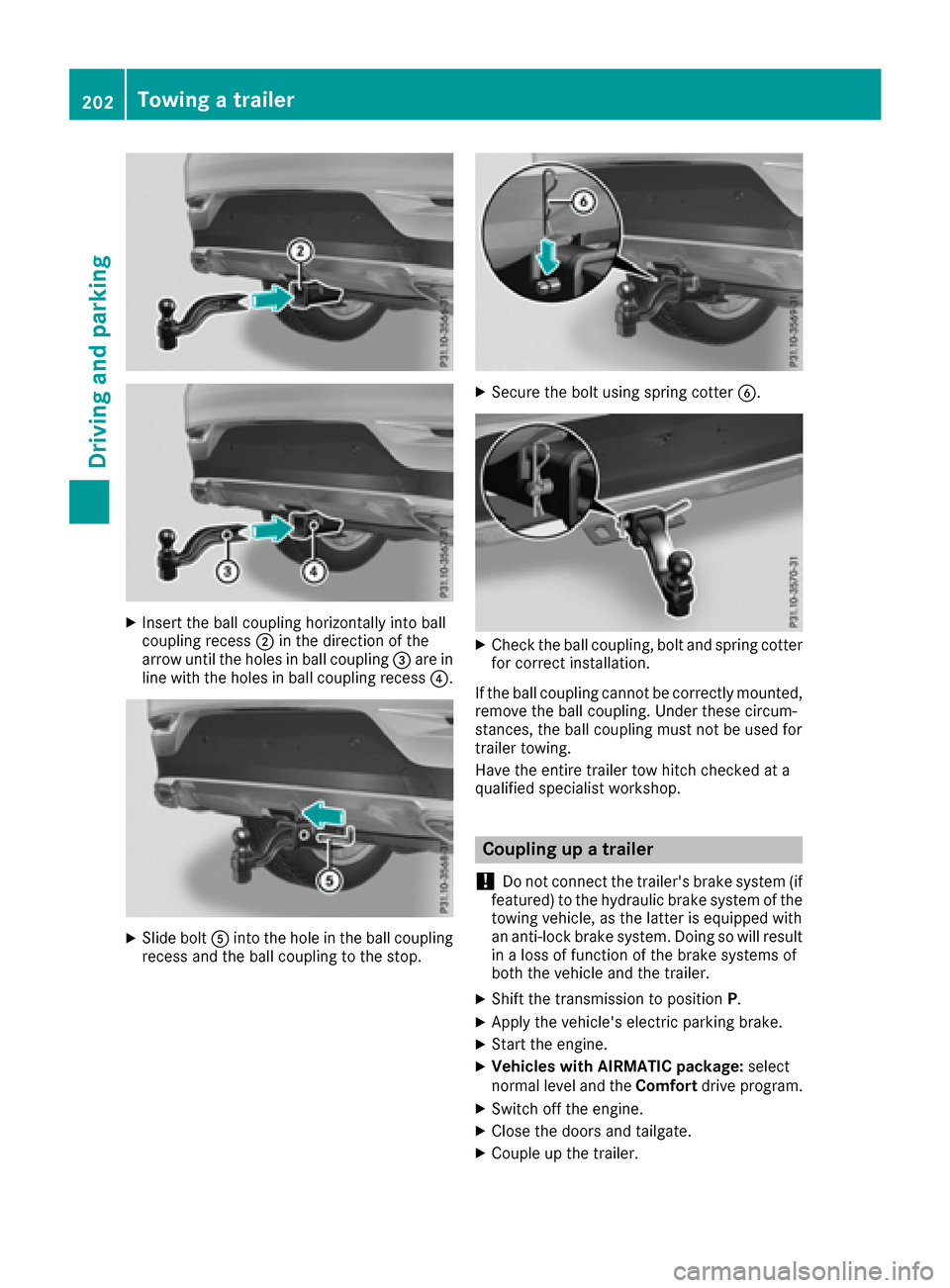
XInsert the ball coupling horizontally into ball
coupling recess;in the direction of the
arrow until the holes in ball coupling =are in
line with the holes in ball coupling recess ?.
XSlide boltAinto the hole in the ball coupling
recess and the ball coupling to the stop.
XSecure the bolt using spring cotter B.
XCheck the ball coupling, bolt and spring cotter
for correct installation.
If the ball coupling cannot be correctly mounted,
remove the ball coupling. Under these circum-
stances, the ball coupling must not be used for
trailer towing.
Have the entire trailer tow hitch checked at a
qualified specialist workshop.
Coupling up a trailer
!
Do not connect the trailer's brake system (if
featured) to the hydraulic brake system of the
towing vehicle, as the latter is equipped with
an anti-lock brake system. Doing so will result
in a loss of function of the brake systems of
both the vehicle and the trailer.
XShift the transmission to position P.
XApply the vehicle's electric parking brake.
XStart the engine.
XVehicles with AIRMATIC package: select
normal level and the Comfortdrive program.
XSwitch off the engine.
XClose the doors and tailgate.
XCouple up the trailer.
202Towing a trailer
Driving and parking
Page 218 of 366
The speed display is inverse to the speedome-
ter.
XPress the=or; button on the steering
wheel to select the Sett.menu.
XPress the:or9 button to select the
Instrument Clustersubmenu.
XConfirm by pressing aon the steering
wheel.
XPress the :or9 button to select the
Permanent Display:function.
The current setting, Outside Temperature,
Speedometer [km/h]or Speedometer[mph]appears.
XTo change the setting: pressaagain.
Light submenu
Setting the daytime running lamps
This function is not available in Canada.
XPress the =or; button on the steering
wheel to select the Sett.menu.
XPress the:or9 button to select the
Lightsubmenu.
XPress ato confirm.
XPress :or9 to select the DaytimeRunning Lightsfunction.
If the DaytimeRunningLightsfunction has
been switched on, the cone of light and the
W symbol in the multifunction display are
shown in orange.
XPress the abutton to save the setting.
Further information on daytime running lamps
(
Ypage 104).
Switching the Intelligent Light System
on/off
XPress the =or; button on the steering
wheel to select the Sett.menu.
XPress the:or9 button to select the
Lightsubmenu.
XPress ato confirm.
XPress the :or9 button to select the
Intell. Light Systemfunction.
If the Intell. Light Systemfunction has
been switched on, the cone of light and the
L symbol in the multifunction display are
shown in orange.
XPress the abutton to save the setting.
When you activate Intell. Light System
,
you activate the following functions:
RHighway mode
RActive light function
RCornering light function
RExtended range fog lamps
Further information on the Intelligent Light Sys-
tem (
Ypage 106).
Vehicle submenu
Activating/deactivating the automatic
door locking mechanism
If you activate the AutomaticDoorLockfunc-
tion, the vehicle is centrally locked above a
speed of approximately 9 mph (15 km/h).
XPress the =or; button on the steering
wheel to select the Sett.menu.
XPress the:or9 button to select the
Vehiclesubmenu.
XPress ato confirm.
XPress the :or9 button to select the
Automatic Door Lockfunction.
When the Automatic Door Lockfunction is
activated, the vehicle doors are displayed in
orange in the multifunction display.
XPress the abutton to save the setting.
For further information on the automatic locking feature, see (
Ypage 78).
Activating/deactivating the acoustic
locking verification signal
If you switch on the AcousticLockfunction, an
acoustic signal sounds when you lock the vehi-
cle.
XPress the =or; button on the steering
wheel to select the Settingsmenu.
XPress the:or9 button to select the
Vehiclesubmenu.
XPress ato confirm.
XPress the :or9 button to select the
Acoustic Lockfunction.
If the Acoustic Lockfunction is activated,
the & symbol in the multifunction display
lights up orange.
XPress the abutton to save the setting.
216Menus and submenus
On-board computer and displays
Page 251 of 366
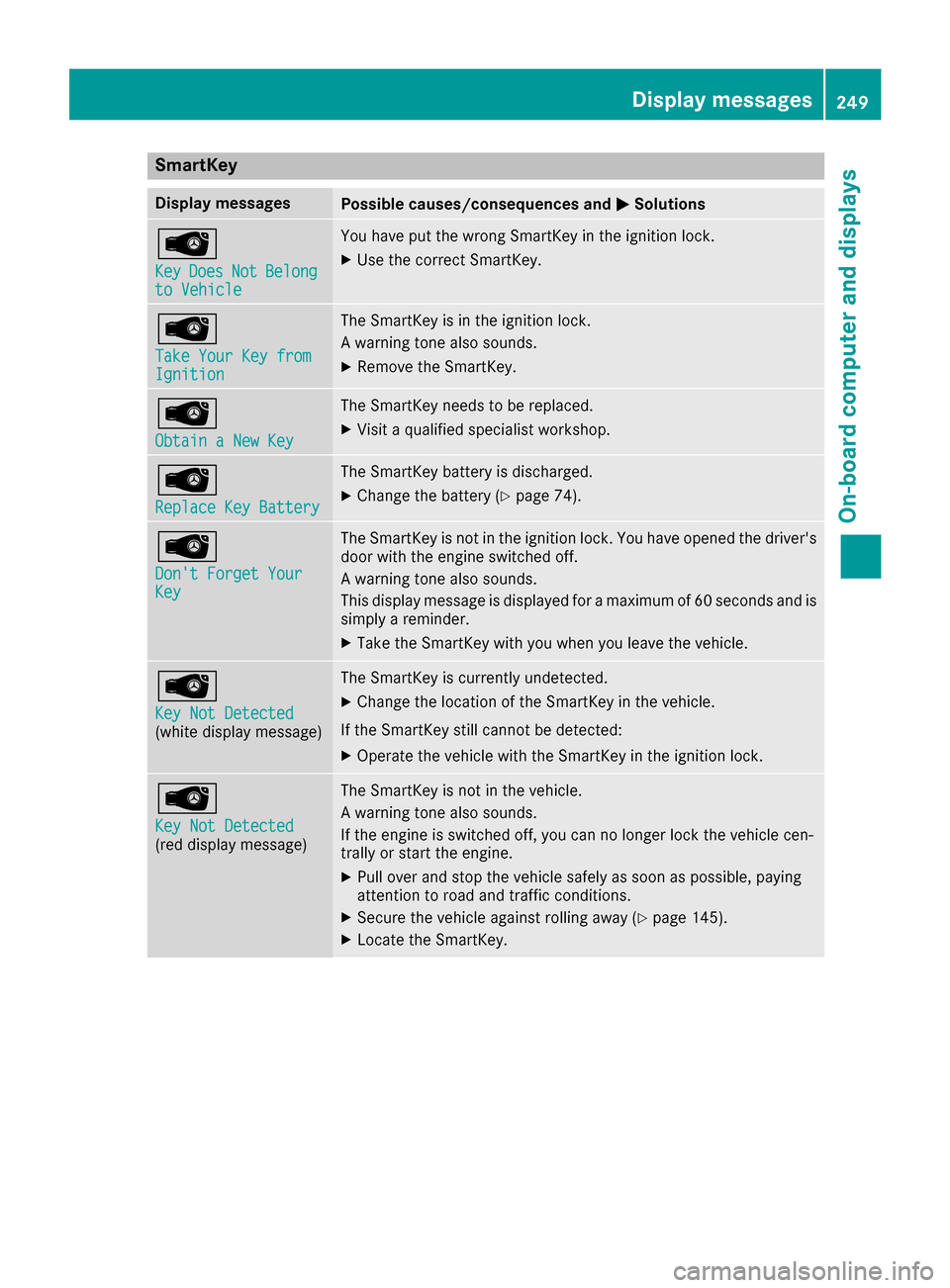
SmartKey
Display messagesPossible causes/consequences andMSolutions
Â
KeyDoesNotBelongto Vehicle
You have put the wrong SmartKey in the ignition lock.
XUse the correct SmartKey.
Â
Take Your Key fromIgnition
The SmartKey is in the ignition lock.
A warning tone also sounds.
XRemove the SmartKey.
Â
Obtain a New Key
The SmartKey needs to be replaced.
XVisit a qualified specialist workshop.
Â
Replace Key Battery
The SmartKey battery is discharged.
XChange the battery (Ypage 74).
Â
Don't Forget YourKey
The SmartKey is not in the ignition lock. You have opened the driver's
door with the engine switched off.
A warning tone also sounds.
This display message is displayed for a maximum of 60 seconds and is
simply a reminder.
XTake the SmartKey with you when you leave the vehicle.
Â
Key Not Detected(white display message)
The SmartKey is currently undetected.
XChange the location of the SmartKey in the vehicle.
If the SmartKey still cannot be detected:
XOperate the vehicle with the SmartKey in the ignition lock.
Â
Key Not Detected(red display message)
The SmartKey is not in the vehicle.
A warning tone also sounds.
If the engine is switched off, you can no longer lock the vehicle cen-
trally or start the engine.
XPull over and stop the vehicle safely as soon as possible, paying
attention to road and traffic conditions.
XSecure the vehicle against rolling away (Ypage 145).
XLocate the SmartKey.
Display messages249
On-board computer and displays
Z
Page 272 of 366
Stowage areas
Loading guidelines
GWARNING
If objects, luggage or loads are not secured or
not secured sufficiently, they could slip, tip
over or be flung around and thereby hit vehicle
occupants. There is a risk of injury, particu-
larly in the event of sudden braking or a sud-
den change in direction.
Always store objects so that they cannot be
flung around. Secure objects, luggage or
loads against slipping or tipping before the
journey.
GWARNING
Combustion engines emit poisonous exhaust
gases such as carbon monoxide. If the tailgate
is open when the engine is running, particu-
larly if the vehicle is moving, exhaust fumes
could enter the passenger compartment.
There is a risk of poisoning.
Turn off the engine before opening the tail-
gate. Never drive with the tailgate open.
GWARNING
The exhaust tail pipe and tail pipe trim can
become very hot. If you come into contact
with these parts of the vehicle, you could burn
yourself. There is a risk of injury.
Always be particularly careful around the
exhaust tail pipe and the tail pipe trim. Allow
these components to cool down before touch-
ing them.
The gross vehicle weight (GVW) is the vehicle
weight including fuel, vehicle tool kit, spare
wheel, installed accessories, vehicle occupants
and luggage/cargo.
Do not exceed the load limit or permitted gross
vehicle weight rating (GVWR) for your vehicle.
The gross load limit and the GVWR are specified
on the vehicle identification plate on the B-pillar
of the driver's door (
Ypage 331).
The load must also be distributed so that the
weight on each axle never exceeds the gross
axle weight rating (GAWR) for the front and rear
axles. The specifications for GVWR and GAWR are on the vehicle identification plate on the B-
pillar of the driver's door (
Ypage 331).
Observe the notes on loading the vehicle
(
Ypage 331).
The handling characteristics of a laden vehicle
are dependent on the distribution of the load
within the vehicle. For this reason, you should
observe the following notes when transporting a
load:
RNever exceed the maximum permissible
gross vehicle mass or the gross axle weight
rating for the vehicle (including occupants).
RThe cargo compartment is the preferred place to carry objects.
RPosition heavy loads as far forwards as pos-
sible and as low down in the cargo compart-
ment as possible.
RThe load must not protrude above the upper
edge of the seat backrests.
RAlways place the load against the rear or frontseat backrests. Make sure that the seat
backrests are securely locked into place.
RAlways place the load behind unoccupied
seats if possible.
RUse the cargo tie-down rings and the parcel
nets to transport loads and luggage.
RUse cargo tie-down rings and fastening mate-
rials appropriate for the weight and size of theload.
RSecure the load with sufficiently strong and
wear-resistant tie-downs. Pad sharp edges for
protection.
Stowage spaces
Important safety notes
GWARNING
If you transport objects in the vehicle interior
and these are not adequately secured, they
could slip or be flung around and thereby
strike vehicle occupants. In addition, cup
holders, open stowage spaces and mobile
phone brackets may not always be able to
hold the objects placed in them in the event of
an accident. There is a risk of injury, particu-
larly in the event of sharp braking or sudden
changes of direction.
270Stowage areas
Stowage and features
Page 280 of 366

RAlways stow objects in such a way that they
cannot be tossed about in these or similar
situations.
RAlways make sure that objects do not pro-
trude out of the stowage spaces, luggage
nets or stowage nets.
REnsure that closable stowage spaces are
shut before beginning your journey.
RAlways stow and secure heavy, hard, poin-
ted, sharp-edged, fragile or large objects in
the cargo compartment.
Observe the loading guidelines (
Ypage 270).
!Only use the cup holders for containers of
the right size and which have lids. The drinks
could otherwise spill.
!Do not expose drinks bottles in the cup
holder in the center console to continuous,
strong and direct sunlight. The passenger
compartment in the area of the center con-
sole can otherwise be damaged by the con-
centrated and reflected sunlight.
Do not keep the KEYLESS-GO key in the tem-
perature-controlled cup holder (
Ypage 278).
Otherwise, the KEYLESS-GO key will not be rec-
ognized.
The stowage compartments in the doors provide
space for bottles with a capacity of up to
34 fl. oz. (1.0 l).
The bottles are not secured or prevented from
tipping over. Therefore, do not place any open
drink containers in the stowage compartments.
Cup holder in the front-compartment
center console
:Cover
;Cup holder
XTo open: slide cover :to its foremost posi-
tion.
XTo close: pull cover :back as far as it will go.
You can remove the cup holder's rubber mat for
cleaning. Clean with clear, lukewarm water only.
Temperature-controlled cup holder in
the front-compartment center console
:Cup holder
;Residual heat indicator lamp
=Switch
The temperature-controlled cup holder can be
used to keep cold drinks cool and warm drinks
warm.
XTurn the SmartKey to position 2in the ignition
lock.
XTo switch on the cooling function: press
and hold button =until the blue indicator
lamp on the button lights up.
XTo switch on the heating function: press
and hold button =until the red indicator
lamp on the button lights up.
XTo switch off the function: press and hold
button =until the indicator lamp on the but-
ton goes out.
When the heating function is used, the metal
insert of the cup holder is heated. Once a certain
temperature is reached, residual heat indicator
lamp ;lights up. This means that the metal
insert of the cup holder is hot. For this reason,
you must not reach into the cup holder metal
insert.
Do not use hard or sharp objects to clean the
cup holder. Use only a soft cloth to clean it.
278Features
Stowage and features
Page 290 of 366
Mercedes-Benz Customer Assistance Center
at 1-800-FOR-MERCedes (1-800-367-6372)
or 1-866-990-9007
You will be asked for your password.
The next time you are inside the vehicle and you
switch on the ignition, the Doors Locked
Remotelymessage appears in the multifunction
display.
Alternatively, the vehicle can be locked via:
Rthe Internet, under the "Owners Online" sec-
tion
Rthe telephone application (e. g. for iPhone®,
Android)
To do this, you will need your identification num-
ber and password.
Stolen vehicle recovery service
If your vehicle has been stolen:
XNotify the police.
The police will issue a numbered incident
report.
XThis number will be forwarded to the
Mercedes-Benz Customer Assistance Center
together with your PIN.
The Mercedes-Benz Customer Assistance
Center then tries to locate the system. The
Mercedes-Benz Customer Assistance Center
contacts you and the local law enforcement
agency if the vehicle is located.
However, only the law enforcement agency is informed of the location of the vehicle.
If the anti-theft alarm system is activated for
longer than 30 seconds, the Mercedes-Benz
Customer Assistance Center is automatically
notified.
Vehicle Health Check
With the Vehicle Health Check, the Customer
Assistance Center can provide improved sup-
port for problems with your vehicle. During an
existing call, vehicle data is transferred to the
Customer Assistance Center.
The customer service representative can use
the received data to decide what kind of assis-
tance is required. You are then, for example,
guided to the nearest Mercedes-Benz Service
Center or a recovery vehicle is called.
If vehicle data needs to be transferred during an
MB Info call or a Roadside Assistance call, this is
initiated by the Customer Assistance Center. The
Roadside Assistance Connected
mes-
sage appears in the display. If the Vehicle Health
Check can be started, the Request
forVehi‐cle Diagnostics Received Start vehi‐cle diagnostics?message appears in the
display.
XPress the Yesbutton to confirm the message.
XWhen the Vehicle Diagnostics PleaseStart Ignitionmessage appears: turn the
SmartKey to position 2in the ignition lock
(
Ypage 125).
XIf the Please follow the instructionsreceivedbyphoneandmoveyourvehi‐cle to a safe position.message
appears: please follow the instructions
received by phone and move your vehicle to a
safe position.
The message in the display disappears.
The vehicle operating state check begins.
During this procedure, you will see the Vehi‐
cle Diagnostics Activemessage.
If you select Cancel
, the Vehicle Health
Check is canceled completely.
When the check is complete, the Sending
vehicle diagnostics data. (Voice con‐nection may be interrupted duringdatatransfer)message appears. The vehicle
data can now be sent.
XPress the OKbutton to confirm the message.
The voice connection with the Customer
Assistance Center is terminated.
The Vehicle Diagnostics: Transfer‐
ring Data...message appears.
The vehicle data is sent to the Customer
Assistance Center.
Depending on what the customer service rep-
resentative agreed with you, the voice connec-
tion is re-established after the transfer is com-
plete. If necessary, you will be contacted at a
later time by another means, e.g. by e-mail or
phone.
Another function of the Vehicle Health Check is
the transfer of service data to the Customer
Assistance Center. If a service is due, the display
shows a message to this effect together with
information about any special offers at your
workshop.
This information can also be called up under
"Owners Online" at http://www.mbusa.com.
Information on the data stored in the vehicle
(
Ypage 29).
288Features
Stowage and features
Page 292 of 366
door opener, contact an authorized Mercedes-
Benz Center.
Alternatively, you can call the following tele-
phone assistance services:
RUSA:Mercedes-Benz Customer Assistance
Center at 1-800-FOR-MERCedes
RCanada: Customer Service at
1-800-387-0100
RHomeLink®hotline 1-800-355-3515 (free of
charge)
More information on HomeLink
®and/or com-
patible products is also available online at
http://www.homelink.co m.
Notes on the declaration of conformity
(
Ypage 27).
USA: FCC ID: CB2HMIHL4
Canada: IC: 279B-HMIHL4
Important safety notes
GWARNING
When you operate or program the garage door
with the integrated garage door opener, per-
sons in the range of movement of the garage
door can become trapped or struck by the
garage door. There is a risk of injury.
When using the integrated garage door
opener, always make sure that nobody is
within the range of movement of the garage
door.
GWARNING
Combustion engines emit poisonous exhaust
gases such as carbon monoxide. Inhaling
these exhaust gases leads to poisoning. There
is a risk of fatal injury. Therefore never leave
the engine running in enclosed spaces with-
out sufficient ventilation.
Programming
Programming buttons
Pay attention to the "Important safety notes"
(Ypage 290).
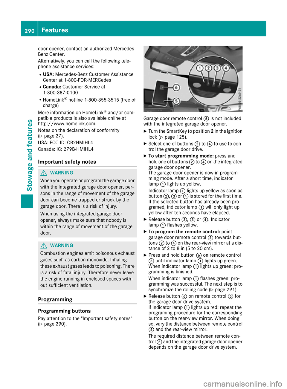
Garage door remote control Ais not included
with the integrated garage door opener.
XTurn the SmartKey to position 2in the ignition
lock (Ypage 125).
XSelect one of buttons ;to? to use to con-
trol the garage door drive.
XTo start programming mode: press and
hold one of buttons ;to? on the integrated
garage door opener.
The garage door opener is now in program-
ming mode. After a short time, indicator
lamp :lights up yellow.
Indicator lamp :lights up yellow as soon as
button ;,=or? is stored for the first time.
If the selected button has already been pro-
gramed, indicator lamp :will only light up
yellow after ten seconds have elapsed.
XRelease button ;,=or?. Indicator
lamp :flashes yellow.
XTo program the remote control: point
garage door remote control Atowards but-
tons ;to? on the rear-view mirror at a dis-
tance of 2 to 8 in (5 to 20 cm).
XPress and hold button Bon remote control
A until indicator lamp :lights up green.
When indicator lamp :lights up green: pro-
gramming is finished.
When indicator lamp :flashes green: pro-
gramming was successful. The next step is to synchronize the rolling code (
Ypage 291).
XRelease button Bon remote control Afor
the garage door drive system.
If indicator lamp :lights up red: repeat the
programing procedure for the corresponding
button on the rear-view mirror. When doing
so, vary the distance between remote control
A and the rear-view mirror.
The required distance between remote con-
trol Aand the integrated garage door opener
depends on the garage door drive system.
290Features
Stowage and features