2017 MERCEDES-BENZ GLE43AMG SUV change wheel
[x] Cancel search: change wheelPage 218 of 366
The speed display is inverse to the speedome-
ter.
XPress the=or; button on the steering
wheel to select the Sett.menu.
XPress the:or9 button to select the
Instrument Clustersubmenu.
XConfirm by pressing aon the steering
wheel.
XPress the :or9 button to select the
Permanent Display:function.
The current setting, Outside Temperature,
Speedometer [km/h]or Speedometer[mph]appears.
XTo change the setting: pressaagain.
Light submenu
Setting the daytime running lamps
This function is not available in Canada.
XPress the =or; button on the steering
wheel to select the Sett.menu.
XPress the:or9 button to select the
Lightsubmenu.
XPress ato confirm.
XPress :or9 to select the DaytimeRunning Lightsfunction.
If the DaytimeRunningLightsfunction has
been switched on, the cone of light and the
W symbol in the multifunction display are
shown in orange.
XPress the abutton to save the setting.
Further information on daytime running lamps
(
Ypage 104).
Switching the Intelligent Light System
on/off
XPress the =or; button on the steering
wheel to select the Sett.menu.
XPress the:or9 button to select the
Lightsubmenu.
XPress ato confirm.
XPress the :or9 button to select the
Intell. Light Systemfunction.
If the Intell. Light Systemfunction has
been switched on, the cone of light and the
L symbol in the multifunction display are
shown in orange.
XPress the abutton to save the setting.
When you activate Intell. Light System
,
you activate the following functions:
RHighway mode
RActive light function
RCornering light function
RExtended range fog lamps
Further information on the Intelligent Light Sys-
tem (
Ypage 106).
Vehicle submenu
Activating/deactivating the automatic
door locking mechanism
If you activate the AutomaticDoorLockfunc-
tion, the vehicle is centrally locked above a
speed of approximately 9 mph (15 km/h).
XPress the =or; button on the steering
wheel to select the Sett.menu.
XPress the:or9 button to select the
Vehiclesubmenu.
XPress ato confirm.
XPress the :or9 button to select the
Automatic Door Lockfunction.
When the Automatic Door Lockfunction is
activated, the vehicle doors are displayed in
orange in the multifunction display.
XPress the abutton to save the setting.
For further information on the automatic locking feature, see (
Ypage 78).
Activating/deactivating the acoustic
locking verification signal
If you switch on the AcousticLockfunction, an
acoustic signal sounds when you lock the vehi-
cle.
XPress the =or; button on the steering
wheel to select the Settingsmenu.
XPress the:or9 button to select the
Vehiclesubmenu.
XPress ato confirm.
XPress the :or9 button to select the
Acoustic Lockfunction.
If the Acoustic Lockfunction is activated,
the & symbol in the multifunction display
lights up orange.
XPress the abutton to save the setting.
216Menus and submenus
On-board computer and displays
Page 246 of 366

Tires
Display messagesPossible causes/consequences andMSolutions
CheckTirePressureSoonThe tire pressure loss warning system has detected a significant loss
in pressure.
A warning tone also sounds.
Possible causes:
Ryou have changed the positions of the wheels and tires or installed
new wheels and tires.
Rthe tire pressure in one or more tires has dropped significantly
GWARNING
Tire pressures that are too low pose the following hazards:
Rthey may burst, especially as the load and vehicle speed increase.
Rthey may wear excessively and/or unevenly, which may greatly
impair tire traction.
Rthe driving characteristics, as well as steering and braking, may be
greatly impaired.
There is a risk of an accident.
XStop the vehicle without making any sudden steering or braking
maneuvers. Pay attention to the traffic conditions as you do so.
XSecure the vehicle against rolling away (Ypage 145).
XCheck the tires and, if necessary, follow the instructions for a flat
tire (Ypage 306).
XCheck the tire pressures and, if necessary, correct the tire pressure.
XRestart the tire pressure loss warning system when the tire pres-
sure is correct (Ypage 328).
CheckTirePressureThen Restart RunFlat Indicator
The tire pressure loss warning system generated a display message
and has not been restarted since.
XSet the correct tire pressure in all four tires.
XRestart the tire pressure loss warning system (Ypage 328).
Run Flat IndicatorInoperativeThe tire pressure loss warning system is faulty.
XVisit a qualified specialist workshop.
PleaseCorrectTirePressureThe tire pressure is too low in at least one of the tires, or the tire
pressure difference between the wheels is too great.
XCheck the tire pressures at the next opportunity (Ypage 328).
XIf necessary, correct the tire pressure.
XRestart the tire pressure monitor (Ypage 330).
244Displa y messages
On-board computer and displays
Page 272 of 366
Stowage areas
Loading guidelines
GWARNING
If objects, luggage or loads are not secured or
not secured sufficiently, they could slip, tip
over or be flung around and thereby hit vehicle
occupants. There is a risk of injury, particu-
larly in the event of sudden braking or a sud-
den change in direction.
Always store objects so that they cannot be
flung around. Secure objects, luggage or
loads against slipping or tipping before the
journey.
GWARNING
Combustion engines emit poisonous exhaust
gases such as carbon monoxide. If the tailgate
is open when the engine is running, particu-
larly if the vehicle is moving, exhaust fumes
could enter the passenger compartment.
There is a risk of poisoning.
Turn off the engine before opening the tail-
gate. Never drive with the tailgate open.
GWARNING
The exhaust tail pipe and tail pipe trim can
become very hot. If you come into contact
with these parts of the vehicle, you could burn
yourself. There is a risk of injury.
Always be particularly careful around the
exhaust tail pipe and the tail pipe trim. Allow
these components to cool down before touch-
ing them.
The gross vehicle weight (GVW) is the vehicle
weight including fuel, vehicle tool kit, spare
wheel, installed accessories, vehicle occupants
and luggage/cargo.
Do not exceed the load limit or permitted gross
vehicle weight rating (GVWR) for your vehicle.
The gross load limit and the GVWR are specified
on the vehicle identification plate on the B-pillar
of the driver's door (
Ypage 331).
The load must also be distributed so that the
weight on each axle never exceeds the gross
axle weight rating (GAWR) for the front and rear
axles. The specifications for GVWR and GAWR are on the vehicle identification plate on the B-
pillar of the driver's door (
Ypage 331).
Observe the notes on loading the vehicle
(
Ypage 331).
The handling characteristics of a laden vehicle
are dependent on the distribution of the load
within the vehicle. For this reason, you should
observe the following notes when transporting a
load:
RNever exceed the maximum permissible
gross vehicle mass or the gross axle weight
rating for the vehicle (including occupants).
RThe cargo compartment is the preferred place to carry objects.
RPosition heavy loads as far forwards as pos-
sible and as low down in the cargo compart-
ment as possible.
RThe load must not protrude above the upper
edge of the seat backrests.
RAlways place the load against the rear or frontseat backrests. Make sure that the seat
backrests are securely locked into place.
RAlways place the load behind unoccupied
seats if possible.
RUse the cargo tie-down rings and the parcel
nets to transport loads and luggage.
RUse cargo tie-down rings and fastening mate-
rials appropriate for the weight and size of theload.
RSecure the load with sufficiently strong and
wear-resistant tie-downs. Pad sharp edges for
protection.
Stowage spaces
Important safety notes
GWARNING
If you transport objects in the vehicle interior
and these are not adequately secured, they
could slip or be flung around and thereby
strike vehicle occupants. In addition, cup
holders, open stowage spaces and mobile
phone brackets may not always be able to
hold the objects placed in them in the event of
an accident. There is a risk of injury, particu-
larly in the event of sharp braking or sudden
changes of direction.
270Stowage areas
Stowage and features
Page 287 of 366
XTo call Roadside Assistance:press Road-
side Assistance button :.
This initiates a call to the Mercedes-Benz Cus-
tomer Assistance Center.
The indicator lamp in Roadside Assistance
button :flashes while the call is active. The
Connecting Call
message appears in the
multifunction display. The audio output is
muted.
If a connection can be made, the Call Con‐
nectedmessage appears in the multifunction
display.
If a mobile phone network and GPS reception
are available, the system transfers data to the
Mercedes-Benz Customer Assistance Center,
for example:
Rcurrent location of the vehicle
Rvehicle identification number
The multimedia system display indicates that a
call is active. During the call, you can change to
the navigation menu by pressing the NAVI but-
ton on the multimedia system, for example.
Voice output is not available in this case.
A voice connection is established between the
Mercedes-Benz Customer Assistance Center
and the vehicle occupants.
From the remote malfunction diagnosis, the
Mercedes-Benz Customer Assistance Center
can ascertain the nature of the problem
(
Ypage 288).
The Mercedes-Benz Customer Assistance Cen-
ter either sends a qualified Mercedes-Benz tech-
nician or makes arrangements for your vehicle
to be transported to the nearest authorized
Mercedes-Benz Center.
You may be charged for services such as repair
work and/or towing.
You can find more information in the separate
mbrace manual.
The system has not been able to initiate a Road-
side Assistance call, if:
Rthe indicator lamp for Roadside Assistance
call button Fis flashing continuous ly.
Rno voice connection to the Mercedes-Benz
Customer Assistance Center was estab-
lished.
This can occur if the relevant mobile phone net-
work is not available, for example.
The Call Failed
message appears in the mul-
tifunction display.
XTo end a call: press the~button on the
multifunction steering wheel.
or
XPress the corresponding multimedia system
button for ending a phone call.
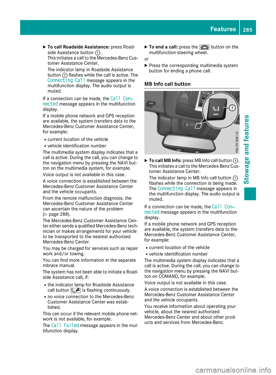
MB Info call button
XTo call MB Info: press MB Info call button :.
This initiates a call to the Mercedes-Benz Cus-
tomer Assistance Center.
The indicator lamp in MB Info call button :
flashes while the connection is being made.
The Connecting Call
message appears in
the multifunction display. The audio output is
muted.
If a connection can be made, the Call Con‐
nectedmessage appears in the multifunction
display.
If a mobile phone network and GPS reception
are available, the system transfers data to the
Mercedes-Benz Customer Assistance Center,
for example:
Rcurrent location of the vehicle
Rvehicle identification number
The multimedia system display indicates that a
call is active. During the call, you can change to
the navigation menu by pressing the NAVI but-
ton on COMAND, for example.
Voice output is not available in this case.
A voice connection is established between the
Mercedes-Benz Customer Assistance Center
and the vehicle occupants.
You receive information about operating your
vehicle, about the nearest authorized
Mercedes-Benz Center and about other prod-
ucts and services from Mercedes-Benz.
Features285
Stowag ean d features
Z
Page 300 of 366
ASSYST PLUS
Service message
The ASSYSTPLU Sservic einterval display
inform syou of th enext servic edue date.
Information on th etyp eof servic eand servic e
intervals (see th eseparat eMaintenance Book -
let).
You can obtain further information from an
authorize dMercedes-Benz Cente ror at
http://www.mbusa.co m(US Aonly).
iThe ASSYS TPLU Sservic einterval display
does no tsho wany information on th eengin e
oil level. Observ eth enote son th eengin eoil
level (
Ypage 295).
The multifunction display shows aservic emes -
sage for several seconds, e.g. :
RService Ain .. Day s
RService ADue
RServic e AOverdu eby .. Day s
Dependingon th eoperating condition sof th e
vehicle, th eremaining time or distanc euntil th e
next servic edue dat eis displayed.
The lette rA
or B,possibl yin connection wit h a
number or another letter, shows th etyp eof ser -
vice. A
stand sfor aminor servic eand Bfora
major service.
You can obtain further information from an
authorize dMercedes-Benz Center.
The ASSYS TPLU Sservic einterval display does
no ttak eint oaccoun tany periods of time during
whic hth ebattery is disconnected.
Maintainin gth etime-dependen tservic esched-
ule:
XNot edown th eservic edue dat edisplayed in
th emultifunction display before disconnect -
ing th ebattery.
or
XAfte rreconnecting th ebattery, subtrac tth e
battery disconnection periods from th eser -
vic edat eshown on th edisplay.
Hiding a service message
XPress th e% ora buttonon th esteering
wheel.
Displaying service messages
XSwitc hon th eignition .
XPress th e= or; buttonon th esteering
whee lto select th eServ.menu.
XPress th e9 or: buttonto select th e
ASSYSTPLU Ssubmen uand confirm by press-
ing th ea button.
The servic edue dat eappear sin th emulti-
function display.
Infor mation about Service
Resetting the ASSYST PLUS service
interval display
!If th eASSYS TPLU Sservic einterval display
has been inadvertentl yreset ,this setting can
be correcte dat aqualified specialist work-
shop.
Hav eservic ewor kcarrie dout as described in
th eMaintenance Booklet .This may otherwise
lead to increased wear and damag eto th e
major assemblies or th evehicle.
A qualified specialist workshop ,e.g. an author-
ized Mercedes-Benz Center, will reset th e
ASSYS TPLU Sservic einterval display after th e
servic ewor khas been carrie dout .You can also
obtain further information on maintenance
work, for example.
Special service requirements
The specifie dmaintenance interval takes only
th enormal operation of th evehicl eint o
account. Under arduous operating condition sor
increased load on th evehicle, maintenance
wor kmus tbe carrie dout mor efrequently, for
example:
Rregular cit ydrivin gwit hfrequen tintermediat e
stops
Rif th evehicl eis primarily used to travel short
distances
Ruse in mountainous terrain or on poor road
surfaces
Rif th eengin eis often lef tidlin gfor lon gperiods
Under these or similar conditions, have, for
example, th eair filter, engin eoil and oil filter
replace dor changed mor efrequently. Under
arduous operating conditions, th etires mus tbe
checke dmor eoften .Further information can be
298ASSYST PLUS
Maintenance and care
Page 306 of 366
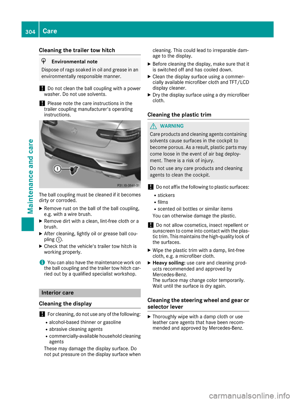
Cleaning the trailer tow hitch
HEnvironmental note
Dispose of rags soaked in oil and grease in an
environmentally responsible manner.
!Do not clean the ball coupling with a power
washer. Do not use solvents.
!Please note the care instructions in the
trailer coupling manufacturer's operating
instructions.
The ball coupling must be cleaned if it becomes
dirty or corroded.
XRemove rust on the ball of the ball coupling,
e.g. with a wire brush.
XRemove dirt with a clean, lint-free cloth or a
brush.
XAfter cleaning, lightly oil or grease ball cou-
pling :.
XCheck that the vehicle's trailer tow hitch is
working properly.
iYou can also have the maintenance work on
the ball coupling and the trailer tow hitch car-
ried out by a qualified specialist workshop.
Interior care
Cleaning the display
!For cleaning, do not use any of the following:
Ralcohol-based thinner or gasoline
Rabrasive cleaning agents
Rcommercially-available household cleaning
agents
These may damage the display surface. Do
not put pressure on the display surface when cleaning. This could lead to irreparable dam-
age to the display.
XBefore cleaning the display, make sure that it
is switched off and has cooled down.
XClean the display surface using a commer-
cially available microfiber cloth and TFT/LCD
display cleaner.
XDry the display surface using a dry microfiber
cloth.
Cleaning the plastic trim
GWARNING
Care products and cleaning agents containing solvents cause surfaces in the cockpit to
become porous. As a result, plastic parts may
come loose in the event of air bag deploy-
ment. There is a risk of injury.
Do not use any care products and cleaning
agents to clean the cockpit.
!Do not affix the following to plastic surfaces:
Rstickers
Rfilms
Rscented oil bottles or similar items
You can otherwise damage the plastic.
!Do not allow cosmetics, insect repellent or
sunscreen to come into contact with the plas-
tic trim. This maintains the high-quality look of
the surfaces.
XWipe the plastic trim with a damp, lint-free
cloth, e.g. a microfiber cloth.
XHeavy soiling: use care and cleaning prod-
ucts recommended and approved by
Mercedes-Benz.
The surface may change color temporarily.
Wait until the surface is dry again.
Cleaning the steering wheel and gear or
selector lever
XThoroughly wipe with a damp cloth or use
leather care agents that have been recom-
mended and approved by Mercedes-Benz.
304Care
Maintenance and care
Page 308 of 366

Where will I find...?
Vehicle tool kit
General notes
The vehicle tool kit can be found in the stowage
well under the cargo compartment floor.
Apart from certain country-specific variations,
the vehicles are not equipped with a tire-change
tool kit. Some tools for changing a wheel are
specific to the vehicle. For more information on
which tools are required to perform a wheel
change on your vehicle, consult a qualified spe-
cialist workshop.
Necessary tire-changing tools can include, for
example:
RJack
RWheel chock
RLug wrench
RRatchet wrench
RAlignment bolt
Vehicles with a TIREFIT kit
:Jack
;Folding wheel chock
=Towing eye
?Alignment bolt
ATire inflation compressor
BLug wrench
CRatchet wrench
DTire sealant filler bottle
XOpen the tailgate.
XLift the cargo compartment floor upwards
(Ypage 276).
XUse the TIREFIT kit (Ypage 308).
Vehicles with a "Minispare" emergency
spare wheel
:Folding wheel chock
;Lug wrench
=Alignment bolt
?Towing eye
AJack
BRatchet wrench
XOpen the tailgate.
XLift the cargo compartment floor upwards
(Ypage 276).
XRemove the "Minispare" emergency spare
wheel (Ypage 347).
Flat tire
Preparing the vehicle
Your vehicle may be equipped with:
RMOExtended tires (tires with run-flat proper-
ties)
Vehicle preparation is not necessary on vehi-
cles with MOExtended tires
Ra TIREFIT kit (Ypage 306)
Ran emergency spare wheel (only for certain
countries)
Information on changing and mounting wheels
(
Ypage 341).
XStop the vehicle on solid, non-slippery and
level ground, as far away as possible from
traffic.
XSwitch on the hazard warning lamps.
XSecure the vehicle against rolling away
(Ypage 145).
XIf possible, bring the front wheels into the
straight-ahead position.
306Flat tire
Breakdown assistance
Page 309 of 366

XVehicles with the AIRMATIC package:
make sure that the normal vehicle level is
selected (
Ypage 171).
XSwitch off the engine.
XVehicles without KEYLESS-GO:remove the
SmartKey from the ignition lock.
XVehicles with KEYLESS-GO: open the driv-
er's door.
The on-board electronics now have status 0.
This is the same as the SmartKey having been
removed.
XVehicles with KEYLESS-GO: remove the
Start/Stop button from the ignition lock
(
Ypage 125).
XMake sure that the engine cannot be started
via your smartphone (Ypage 127).
XMake sure that the passengers are not endan-
gered as they do so. Make sure that no one is
near the danger area while a wheel is being
changed. Anyone who is not directly assisting
in the wheel change should, for example,
stand behind the barrier.
XGet out of the vehicle. Pay attention to traffic
conditions when doing so.
XClose the driver's door.
XUnload heavy luggage.
iOnly operate the tire inflation compressor
using a 12 V socket, even if the ignition is
turned off (
Ypage 280).
An emergency cut-out ensures that the on-
board voltage does not drop too low. If the on-
board voltage is too low, the power to the
sockets is automatically cut. This ensures
that there is sufficient power to start the
engine.
MOExtended tires (tires with run-flat
properties)
General notes
With MOExtended tires (tires with run flat char-
acteristics), you can continue to drive your vehi-
cle even if there is a total loss of pressure in one
or more tires. The affected tire must not show
any clearly visible damage.
You can recognize MOExtended tires by the
MOExtended marking which appears on the
sidewall of the tire. You will find this marking
next to the tire size designation, the load-bear-
ing capacity and the speed index (
Ypage 335). MOExtended tires may only be used in conjunc-
tion with an active tire pressure loss warning
system or with an active tire pressure monitor.
If a pressure loss warning message appears
in the multifunction display:
Robserve the instructions in the display mes-
sages (Ypage 244).
Rcheck the tire for damage.
Rif driving on, observe the following notes.
The driving distance possible in run-flat mode is
approximately 50 miles (80 km) when the vehi-
cle is partially laden and approximately 18 miles
(30 km) when the vehicle is fully laden.
In addition to the vehicle load, the driving dis-
tance possible depends upon:
Rvehicle speed
Rroad condition
Routside temperature
The driving distance possible in run-flat mode
may be reduced by extreme driving conditions
or maneuvers, or it can be increased through a
moderate style of driving.
The driving dista
nce possible in run-flat mode is
counted from the moment the tire pressure loss
warning appears in the multifunction display.
You must not exceed a maximum speed of
50 mph (80 km/h).
When replacing one or all tires, please observe
the following specifications for your vehicle's
tires:
Rsize
Rtype and
Rthe "MOExtended" mark
Vehicles equipped with MOExtended tires are
not equipped with a TIREFIT kit at the factory. It
is therefore recommended that you additionally
equip your vehicle with a TIREFIT kit if you mount tires that do not feature run-flat properties, e.g.
winter tires. A TIREFIT kit may be obtained from
a qualified specialist workshop.
Important safety notes
GWARNING
When driving in emergency mode, the driving
characteristics deteriorate, e.g. when corner-
ing, accelerating quickly and when braking.
There is a risk of an accident.
Flat tire307
Breakdown assistance
Z