2017 MERCEDES-BENZ GLE towing
[x] Cancel search: towingPage 340 of 390
In order to ensure that the automatic transmis-
sion stays in position N when towing the vehicle,
you must observe the following points: X
Make sure that the vehicle is stationary. X
Turn the SmartKey to position 2 in the ignition
lock. X
Depress and hold the brake pedal. X
Shift the automatic transmission to position
N . X
Leave the SmartKey in position 2 in the igni-
tion lock. X
Release the brake pedal. X
Release the electric parking brake. X
Switch on the hazard warning lamps
( Y
page 109).
In order to signal a change of direction when
towing the vehicle with the hazard warning
lamps switched on, use the combination switch
as usual. In this case, only the indicator lamps
for the direction of travel flash. After resetting
the combination switch, the hazard warning
lamp starts flashing again.
Transporting the vehicle
4MATIC vehicles/vehicles with auto-
matic transmission
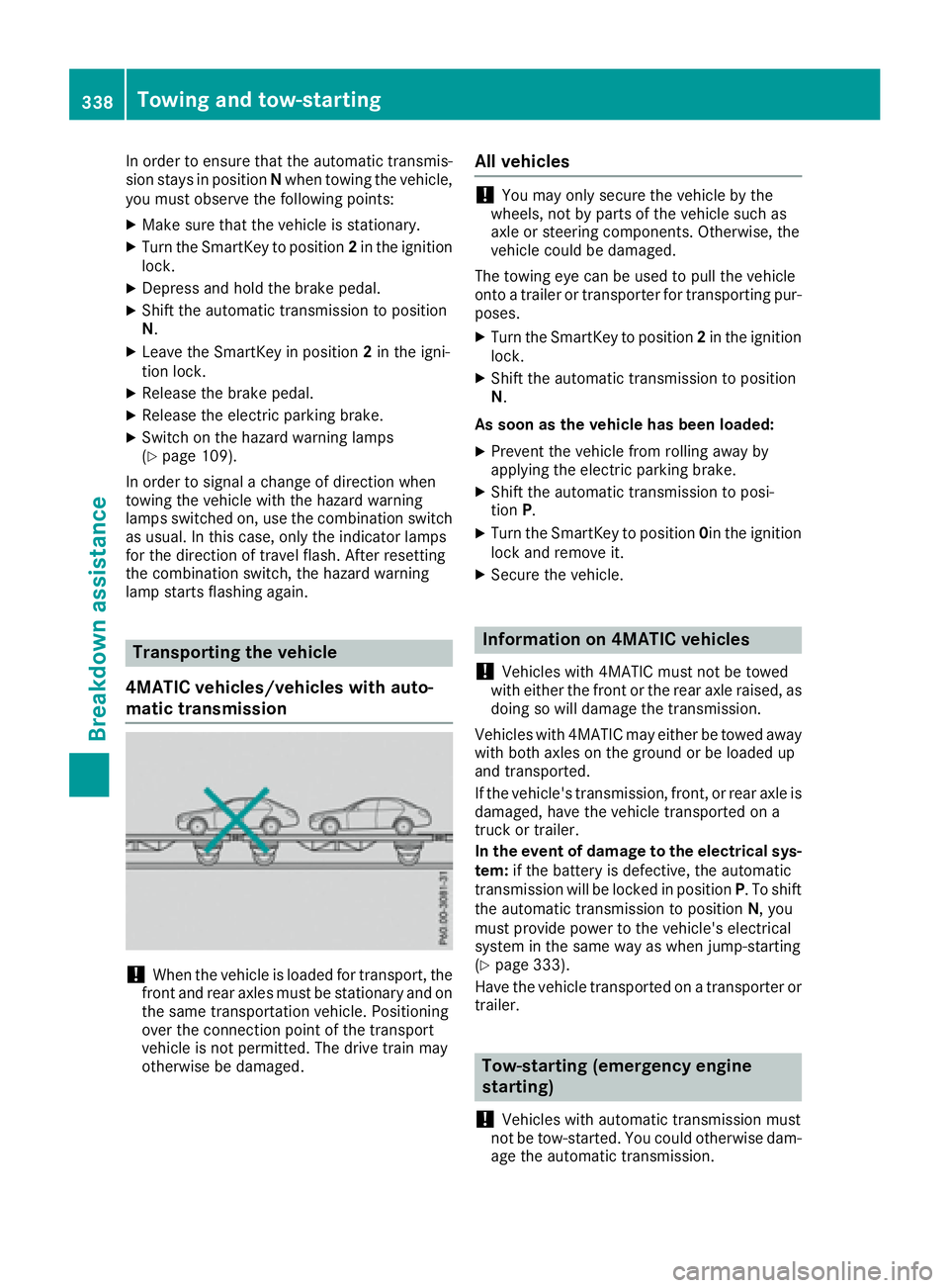
! When the vehicle is loaded for transport, the
front and rear axles must be stationary and on
the same transportation vehicle. Positioning
over the connection point of the transport
vehicle is not permitted. The drive train may
otherwise be damaged. All vehicles
! You may only secure the vehicle by the
wheels, not by parts of the vehicle such as
axle or steering components. Otherwise, the
vehicle could be damaged.
The towing eye can be used to pull the vehicle
onto a trailer or transporter for transporting pur-
poses. X
Turn the SmartKey to position 2 in the ignition
lock. X
Shift the automatic transmission to position
N .
As soon as the vehicle has been loaded: X
Prevent the vehicle from rolling away by
applying the electric parking brake. X
Shift the automatic transmission to posi-
tion P . X
Turn the SmartKey to position 0 in the ignition
lock and remove it. X
Secure the vehicle.
Information on 4MATIC vehicles
! Vehicles with 4MATIC must not be towed
with either the front or the rear axle raised, as
doing so will damage the transmission.
Vehicles with 4MATIC may either be towed away
with both axles on the ground or be loaded up
and transported.
If the vehicle's transmission, front, or rear axle is
damaged, have the vehicle transported on a
truck or trailer.
In the event of damage to the electrical sys-
tem: if the battery is defective, the automatic
transmission will be locked in position P . To shift
the automatic transmission to position N , you
must provide power to the vehicle's electrical
system in the same way as when jump-starting
( Y
page 333).
Have the vehicle transported on a transporter or
trailer.
Tow-starting (emergency engine
starting)
! Vehicles with automatic transmission must
not be tow-started. You could otherwise dam-
age the automatic transmission.338
Towing and tow-starting
Breakdown assistance
Page 355 of 390

able cargo and luggage load capacity is
650 lbs (1400 - 750 (5 x 150) = 650 lbs). X
Step 5: Determine the combined weight of
luggage and cargo being loaded on the vehi- cle. That weight may not safely exceed the
available cargo and luggage load capacity cal-
culated in step 4.
Example: steps 1 to 3 The following table shows examples on how to calculate total and cargo load capacities with varying
seating configurations and number and size of occupants. The following examples use a load limit of
1500 lbs (680 kg). This is for illustration purposes only. Make sure you are using the actual load
limit for your vehicle stated on your vehicle's Tire and Loading Information placard ( Y
page 351).
The greater the combined weight of the occupants, the lower the maximum luggage load.
Additional information when towing a trailer ( Y
page 216).
Step 1
Example 1 Example 2 Example 3
Combined maximum
weight of occupants
and cargo (data from
the Tire and Loading
Information placard) 1500 lbs (680 kg) 1500 lbs (680 kg) 1500 lbs (680 kg)
Step 2
Example 1 Example 2 Example 3
Number of people in
the vehicle (driver and
occupants) 5 3 1
Distribution of the
occupants Front: 2
Rear: 3 Front: 1
Rear: 2 Front: 1
Weight of the occu-
pants Occupant 1: 150 lbs
(68 kg)
Occupant 2: 180 lbs
(82 kg)
Occupant 3: 160 lbs
(73 kg)
Occupant 4: 140 lbs
(63 kg)
Occupant 5: 120 lbs
(54 kg) Occupant 1: 200 lbs
(91 kg)
Occupant 2: 190 lbs
(86 kg)
Occupant 3: 150 lbs
(68 kg) Occupant 1: 150 lbs
(68 kg)
Gross weight of all
occupants 750 lbs (340 kg) 540 lbs (245 kg) 150 lbs (68 kg)Loading the vehicle 353
Wheels and tires Z
Page 369 of 390
R
do not switch ESP ®
off.R
have a spare wheel or emergency spare
wheel of a different size replaced at the
nearest qualified specialist workshop.
Observe that the wheel and tire dimensions
as well as the tire type must be correct.
! Mercedes-AMG vehicles with
"Minispare" emergency spare wheel: only
use the "Minispare" emergency spare wheel
on the rear axle . If you mount the
"Minispare" emergency spare wheel on the
front axle, this could result in damage to the
brake system.
If a tire on the front axle is defective, an intact
wheel from the rear axle must first be
replaced with the "Minispare" emergency
spare wheel. The damaged wheel on the front
axle can then be replaced by the undamaged
wheel from the rear axle.
Make sure to note the placard on the
"Minispare" emergency spare wheel.
When using an emergency spare wheel or spare
wheel of a different size, you must not exceed
the maximum speed of 50 mph (80 km/ h) .
Snow chains must not be mounted on emer-
gency spare wheels.
General notes You can ask for information regarding permitted
emergency spare wheels at an authorized
Mercedes-Benz Center.
Mounting the emergency spare wheel is descri-
bed under "Mounting a wheel" ( Y
page 362).
You should regularly check the pressure of the
emergency spare wheel, particularly prior to
long trips, and correct the pressure as neces-
sary ( Y
page 344). The value on the wheel is
valid.
An emergency spare wheel may also be moun-
ted against the direction of rotation. Observe
the time restriction on use as well as the speed
limitation specified on the emergency spare
wheel.
Replace the tires after six years at the latest,
regardless of wear. This also applies to the
emergency spare wheel.
When you are driving with the collapsible spare
wheel mounted, the tire pressure loss warning
system or the tire pressure monitor cannot func- tion reliably. Only restart the tire pressure loss
warning system or tire pressure monitor when
the defective wheel has been replaced with a
new wheel.
Vehicles with tire pressure monitor: after
mounting an emergency spare wheel, the sys-
tem may still display the tire pressure of the
removed wheel for a few minutes. The value dis-
played for the mounted emergency spare wheel
is not the same as the current tire pressure of
the e mergency spare wheel.
Removing/stowing the emergency
spare wheel
Vehicles with a "Minispare" emergency
spare wheel under the cargo compart-
ment floor Always observe the instructions and safety
notes in the "Mounting a wheel" section
( Y
page 362).
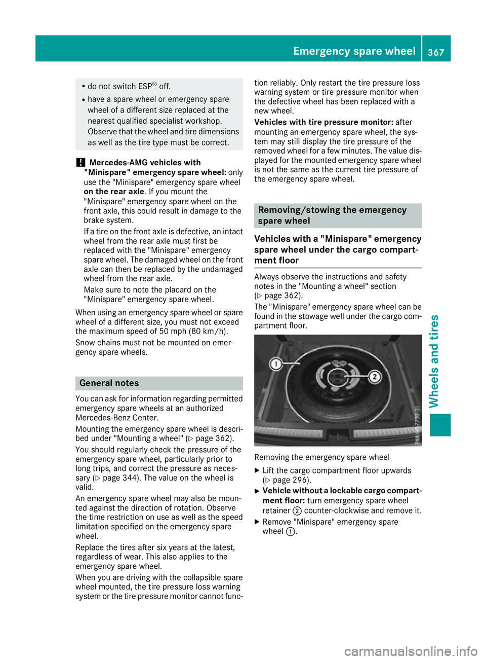
The "Minispare" emergency spare wheel can be
found in the stowage well under the cargo com-
partment floor.
Removing the emergency spare wheel X
Lift the cargo compartment floor upwards
( Y
page 296). X
Vehicle without a lockable cargo compart-
ment floor: turn emergency spare wheel
retainer D counter-clockwise and remove it. X
Remove "Minispare" emergency spare
wheel C .Emergency spare wheel 367
Wheels and tires Z
Page 371 of 390
Inflating the collapsible spare wheel
( Y
page 369).
Take the following steps to stow a used collaps-
ible spare wheel. Otherwise, it will not fit into the
spare wheel well. Mercedes-Benz recommends
that you have this work performed at a qualified
specialist workshop, e.g. at an authorized
Mercedes-Benz Center.
Stowing the emergency spare wheel X
Unscrew the valve cap from the valve. X
If possible, unscrew the valve insert from the
valve and release the air.
i Fully deflating the tires can take a few
minutes. X
Screw the valve insert back into the valve. X
Screw the valve cap back on. X
Lay collapsible spare wheel C in the emer-
gency spare wheel well. X
Screw in retaining screw D clockwise in the
collapsible emergency wheel to the stop. X
Swing the cargo compartment floor down
( Y
page 296).
Mercedes-AMG vehicles with a collaps-
ible spare wheel in the emergency
spare wheel bag Always observe the instructions and safety
notes in the "Mounting a wheel" section
( Y
page 362).
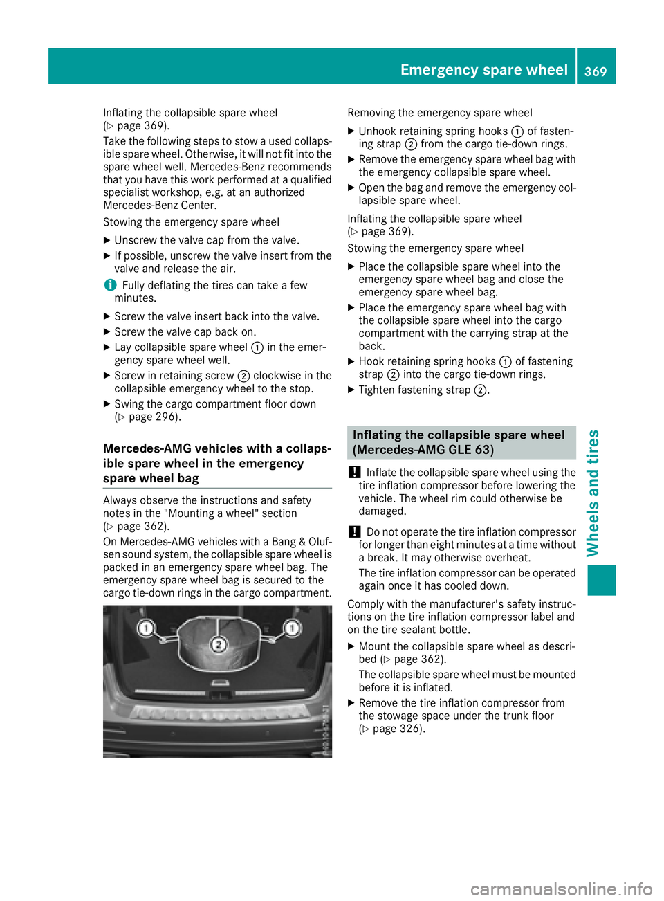
On Mercedes-AMG vehicles with a Bang & Oluf-
sen sound system, the collapsible spare wheel is
packed in an emergency spare wheel bag. The
emergency spare wheel bag is secured to the
cargo tie-down rings in the cargo compartment. Removing the emergency spare wheel X
Unhook retaining spring hooks C of fasten-
ing strap D from the cargo tie-down rings. X
Remove the emergency spare wheel bag with
the emergency collapsible spare wheel. X
Open the bag and remove the emergency col-
lapsible spare wheel.
Inflating the collapsible spare wheel
( Y
page 369).
Stowing the emergency spare wheel X
Place the collapsible spare wheel into the
emergency spare wheel bag and close the
emergency spare wheel bag. X
Place the emergency spare wheel bag with
the collapsible spare wheel into the cargo
compartment with the carrying strap at the
back. X
Hook retaining spring hooks C of fastening
strap D into the cargo tie-down rings. X
Tighten fastening strap D .
Inflating the collapsible spare wheel
(Mercedes-AMG GLE 63)
! Inflate the collapsible spare wheel using the
tire inflation compressor before lowering the
vehicle. The wheel rim could otherwise be
damaged.
! Do not operate the tire inflation compressor
for longer than eight minutes at a time without
a break. It may otherwise overheat.
The tire inflation compressor can be operated
again once it has cooled down.
Comply with the manufacturer's safety instruc-
tions on the tire inflation compressor label and
on the tire sealant bottle. X
Mount the collapsible spare wheel as descri-
bed ( Y
page 362).
The collapsible spare wheel must be mounted
before it is inflated. X
Remove the tire inflation compressor from
the stowage space under the trunk floor
( Y
page 326).Emergency spare wheel 369
Wheels and tires Z