2017 MERCEDES-BENZ GLE display
[x] Cancel search: displayPage 309 of 390
The mobile phone is no longer connected to the
multimedia system.
However, if you want to use your mobile phone,
do so only when the vehicle is stationary and in
a safe location.
Downloading destinations in COMAND Downloading destinations Downloading destinations gives you access to a
database with over 15 million points of interest
(POIs). These can be downloaded on the navi-
gation system in your vehicle. If you know the
destination, the address can be downloaded.
Alternatively, you can obtain the location of
Points of Interest (POIs)/important destinations
in the vicinity.
Furthermore, you can download routes with up
to four way points.
You are prompted to confirm route guidance to
the address entered. X
Select Yes by turning 3 or sliding 1
the controller and confirm with 7 .
The system calculates the route and subse-
quently starts the route guidance with the
address entered.
If you select No the address can be stored in
the address book.
The destination download function is available
if: R
the vehicle is equipped with a navigation sys-
tem. R
the relevant mobile phone network is availa-
ble and data transfer is possible.
Route Assistance
This service is part of the mbrace PLUS Package
and cannot be purchased separately.
You can use the Route Assistance function even
if the vehicle is not equipped with a navigation
system.
Within the framework of this service, you receive
a professional and reliable form of navigation
support without having to leave your vehicle.
The customer service representative finds a
suitable route depending on your vehicle's cur-
rent position and the desired destination. You
will then be guided live through the current route
section. Search & Send General notes To use "Search & Send", your vehicle must be
equipped with mbrace and a navigation system.
Additionally, an mbrace service subscription
must be completed.
"Search & Send" is a destination entry service. A
destination address which is found on Google
Maps ®
can be transferred via mbrace directly to
your vehicle's navigation system.
Specifying and sending the destination
address X
Go to the website http://maps.google.com
and enter a destination address into the entry
field. X
To send the destination address to the e-
mail address of your mbrace account:
click on the corresponding button on the web-
site.
Example:
If you select 'Send to vehicle' and then
'Mercedes-Benz', the destination address will
be sent to your vehicle. X
When the "Send" dialog window appears:
Enter the e-mail address you specified when
setting up your mbrace account into the cor-
responding field. X
Click "Send".
Information on specific commands such as
"Address entry" or "Send" can be found on the
website.
Calling up a transmitted destination
address X
Turn the SmartKey to position 2 in the ignition
lock ( Y
page 132).
The transmitted destination address is loaded
into the vehicle's navigation system.
A display message appears, asking whether
navigation should be started. X
Select Yes by turning 3 or sliding 1
the controller and confirm with 7 .
The system calculates the route and subse-
quently starts the route guidance with the
address entered.
If you select No
the address can be stored in
the address book. Features 307
Stowage and features Z
Page 310 of 390
If you have sent more than one destination
address, each individual destination must be
confirmed separately.
Destination addresses are loaded in the same
order as the order in which they were sent.
If you own multiple Mercedes-Benz vehicles with
mbrace and activated mbrace accounts:
If multiple vehicles are registered under the
same e-mail address, the destination will be
sent to all the vehicles.
Vehicle remote opening You can use the vehicle remote opening if you
have unintentionally locked your vehicle and a
replacement SmartKey is not available.
The vehicle can be opened by the Mercedes-
Benz Customer Assistance Center.
The vehicle can be immediately opened
remotely within four days of the ignition being
turned off. After this time, the remote unlocking
may be delayed by 15 to 60 minutes. After
30 days, the vehicle can no longer be opened
remotely.
The vehicle remote unlocking feature is availa-
ble if the relevant mobile phone network is avail-
able and a data connection is possible. X
Contact the following service hotlines:
Mercedes-Benz Customer Assistance Center
at 1-800-FOR-MERCedes (1-800-367-6372)
or 1-866-990-9007
You will be asked for your password. X
Return to your vehicle at the time agreed upon
with the Mercedes-Benz Customer Assis-
tance Center.
Alternatively, the vehicle can be opened via: R
the Internet, under the "Owners Online" sec-
tion R
the telephone application (e. g. for iPhone ®
,
Android)
To do this, you will need your identification num-
ber and password.
Vehicle remote closing
The vehicle remote-closing feature can be used
when you have forgotten to lock the vehicle and
you are no longer nearby.
The vehicle can then be locked by the Mercedes-
Benz Customer Assistance Center. The vehicle can be immediately remotely locked
within four days of the ignition being turned off.
After this time, remote closing may be delayed
by 15 to 60 minutes. After 30 days the vehicle
can no longer be locked remotely.
The vehicle remote closing feature is available if
the relevant mobile phone network is available
and a data connection is possible. X
Contact the following service hotlines:
Mercedes-Benz Customer Assistance Center
at 1-800-FOR-MERCedes (1-800-367-6372)
or 1-866-990-9007
You will be asked for your password.
The next time you are inside the vehicle and you
switch on the ignition, the Doors Locked
Remotely message appears in the multifunction
display.
Alternatively, the vehicle can be locked via: R
the Internet, under the "Owners Online" sec-
tion R
the telephone application (e. g. for iPhone ®
,
Android)
To do this, you will need your identification num-
ber and password.
Stolen vehicle recovery service If your vehicle has been stolen: X
Notify the police.
The police will issue a numbered incident
report. X
This number will be forwarded to the
Mercedes-Benz Customer Assistance Center
together with your PIN.
The Mercedes-Benz Customer Assistance
Center then tries to locate the system. The
Mercedes-Benz Customer Assistance Center
contacts you and the local law enforcement
agency if the vehicle is located.
However, only the law enforcement agency is
informed of the location of the vehicle.
If the anti-theft alarm system is activated for
longer than 30 seconds, the Mercedes-Benz
Customer Assistance Center is automatically
notified.
Vehicle Health Check
With the Vehicle Health Check, the Customer
Assistance Center can provide improved sup-
port for problems with your vehicle. During an308
Features
Stowage and features
Page 311 of 390
existing call, vehicle data is transferred to the
Customer Assistance Center.
The customer service representative can use
the received data to decide what kind of assis-
tance is required. You are then, for example,
guided to the nearest Mercedes-Benz Service
Center or a recovery vehicle is called.
If vehicle data needs to be transferred during an
MB Info call or a Roadside Assistance call, this is
initiated by the Customer Assistance Center.
The Roadside Assistance Connected mes-
sage appears in the display. If the Vehicle Health
Check can be started, the Request for Vehi‐
cle Diagnostics Received Start vehi‐
cle diagnostics? message appears in the
display. X
Press the Yes button to confirm the message.X
When the Vehicle Diagnostics Please
Start Ignition message appears: turn the
SmartKey to position 2 in the ignition lock
( Y
page 132). X
If the Please follow the instructions
received by phone and move your vehi‐
cle to a safe position. message
appears: please follow the instructions
received by phone and move your vehicle to a
safe position.
The message in the display disappears.
The vehicle operating state check begins.
During this procedure, you will see the Vehi‐
cle Diagnostics Active message.
If you select Cancel
, the Vehicle Health
Check is canceled completely.
When the check is complete, the Sending
vehicle diagnostics data. (Voice con‐
nection may be interrupted during
data transfer) message appears. The vehicle
data can now be sent. X
Press the OK button to confirm the message.
The voice connection with the Customer
Assistance Center is terminated.
The Vehicle Diagnostics: Transfer‐
ring Data... message appears.
The vehicle data is sent to the Customer
Assistance Center.
Depending on what the customer service rep-
resentative agreed with you, the voice connec-
tion is re-established after the transfer is com-
plete. If necessary, you will be contacted at a
later time by another means, e.g. by e-mail or
phone. Another function of the Vehicle Health Check is
the transfer of service data to the Customer
Assistance Center. If a service is due, the display
shows a message to this effect together with
information about any special offers at your
workshop.
This information can also be called up under
"Owners Online" at http://www.mbusa.com.
Information on the data stored in the vehicle
( Y
page 30).
Information on Roadside Assistance
( Y
page 27).
Downloading routes Downloading routes allows you to transfer and
save predefined routes in the navigation sys-
tem.
A route can be prepared and sent by either a
customer service representative or under "Own-
ers Online" at http://www.mbusa.com.
Each route can include up to four way points.
Once a route has been received by the naviga-
tion system, you will see the Do you want to
start route guidance? Destination
Received destination has been saved
in "Previous destinations". message on
the multimedia system display.
The route is saved. X
To start route guidance: select Yes .
An overview of the route is shown in the dis-
play.
If you select No , the saved route can be called
up later in the navigation menu. X
Select Start .
Route guidance starts.
Downloaded and saved routes can be called up
again.
Speed alert You can define the upper speed limit, which
must not be exceeded by the vehicle.
If this selected speed is exceeded by the vehicle,
a message will be sent to the Customer Assis-
tance Center. The Customer Assistance Center
then forwards this information to you.
You can select the way in which you receive this
information beforehand. Possible options
include text message, e-mail or an automated
call. Features 309
Stowage and features Z
Page 319 of 390
Where possible, let the engine cool down and
touch only the components described in the
following.
G WARNING
The cooling system is pressurized, particularly
when the motor is warm. If you open the cap,
you could be scalded if hot coolant sprays out.
There is a risk of injury.
Let the engine cool down before you open the
cap. Wear gloves and eye protection. Slowly
open the cap to relieve pressure.
G WARNING
Windshield washer concentrate could ignite if
it comes into contact with hot engine compo-
nents or the exhaust system. There is a risk of
fire and injury.
Make sure that no windshield washer con-
centrate is spilled next to the filler neck.
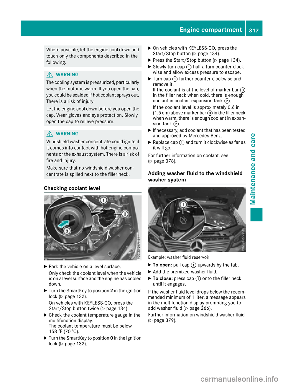
Checking coolant level
X
Park the vehicle on a level surface.
Only check the coolant level when the vehicle
is on a level surface and the engine has cooled
down. X
Turn the SmartKey to position 2 in the ignition
lock ( Y
page 132).
On vehicles with KEYLESS-GO, press the
Start/Stop button twice ( Y
page 134).X
Check the coolant temperature gauge in the
multifunction display.
The coolant temperature must be below
158 ‡ (70 †). X
Turn the SmartKey to position 0 in the ignition
lock ( Y
page 132). X
On vehicles with KEYLESS-GO, press the
Start/Stop button ( Y
page 134).X
Press the Start/Stop button ( Y
page 134).X
Slowly turn cap �C half a turn counter-clock-
wise and allow excess pressure to escape. X
Turn cap �C further counter-clockwise and
remove it.
If the coolant is at the level of marker bar �
Page 320 of 390
ASSYST PLUS
Service message The ASSYS T PLU S servic e interval display
inform s you of th e next servic e due date.
Information on th e typ e of servic e and servic e
intervals (see th e separat e Maintenance Book -
let).
You can obtain further information from an
authorize d Mercedes-Benz Cente r or at
http://www.mbusa.co m (US A only).
i The ASSYS T PLU S servic e interval display
does no t sho w any information on th e engin e
oil level. Observ e th e note s on th e engin e oil
level ( Y
page 315).
The multifunction display shows a servic e mes -
sage for several seconds, e.g. :R
Servic e A in .. Day sR
Servic e A DueR
Servic e A Overdu e by .. Day s
Dependin g on th e operating condition s of th e
vehicle, th e remaining time or distanc e until th e
next servic e due dat e is displayed.
The lette r A or B , possibl y in connection wit h a
number or another letter, shows th e typ e of ser -
vice. A stand s for a minor servic e and B for a
major service.
You can obtain further information from an
authorize d Mercedes-Benz Center.
The ASSYS T PLU S servic e interval display does
no t tak e int o accoun t any periods of time during
whic h th e battery is disconnected.
Maintainin g th e time-dependen t servic e sched-
ule: X
Not e down th e servic e due dat e displayed in
th e multifunction display before disconnect -
ing th e battery.
or X
Afte r reconnecting th e battery, subtrac t th e
battery disconnection periods from th e ser -
vic e dat e shown on th e display.
Hiding a service message X
Press th e �8 or �v butto n on th e steering
wheel. Displaying service messages X
Switc h on th e ignition .X
Press th e �Y or �e butto n on th e steering
whee l to select th e Serv. menu.X
Press th e �c or �d butto n to select th e
ASSYST PLU S submen u and confirm by press-
ing th e �v button.
The servic e due dat e appear s in th e multi-
function display.
Infor ma ti on about Service
Resetting the ASSYST PLUS service
interval display
! If th e ASSYS T PLU S servic e interval display
has been inadvertentl y reset , this setting can
be correcte d at a qualified specialist work-
shop.
Hav e servic e wor k carrie d out as described in
th e Maintenance Booklet . This may otherwise
lead to increased wear and damag e to th e
major assemblies or th e vehicle.
A qualified specialist workshop , e.g. an author-
ized Mercedes-Benz Center, will reset th e
ASSYS T PLU S servic e interval display after th e
servic e wor k has been carrie d out . You can also
obtain further information on maintenance
work, for example.
Special service requirements The specifie d maintenance interval takes only
th e normal operation of th e vehicl e int o
account. Under arduous operating condition s or
increased load on th e vehicle, maintenance
wor k mus t be carrie d out mor e frequently, for
example: R
regular cit y drivin g wit h frequen t intermediat e
stops R
if th e vehicl e is primarily used to travel short
distances R
use in mountainous terrain or on poor road
surfaces R
if th e engin e is often lef t idlin g for lon g periods
Under these or similar conditions, have, for
example, th e air filter, engin e oil and oil filter
replace d or changed mor e frequently. Under
arduous operating conditions, th e tires mus t be
checke d mor e often . Further information can be318
ASSYST PLUS
Maintenance and care
Page 326 of 390
Cleaning the trailer tow hitch
H Environmental note
Dispose of rags soaked in oil and grease in an
environmentally responsible manner.
! Do not clean the ball coupling with a power
washer. Do not use solvents.
! Please note the care instructions in the
trailer coupling manufacturer's operating
instructions.
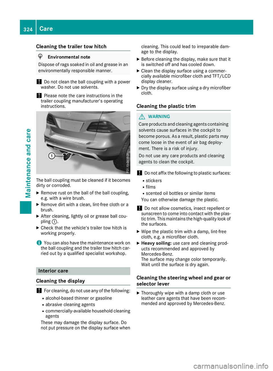
The ball coupling must be cleaned if it becomes
dirty or corroded. X
Remove rust on the ball of the ball coupling,
e.g. with a wire brush. X
Remove dirt with a clean, lint-free cloth or a
brush. X
After cleaning, lightly oil or grease ball cou-
pling �C .X
Check that the vehicle's trailer tow hitch is
working properly.
i You can also have the maintenance work on
the ball coupling and the trailer tow hitch car-
ried out by a qualified specialist workshop.
Interior care
Cleaning the display
! For cleaning, do not use any of the following: R
alcohol-based thinner or gasoline R
abrasive cleaning agents R
commercially-available household cleaning
agents
These may damage the display surface. Do
not put pressure on the display surface when cleaning. This could lead to irreparable dam-
age to the display. X
Before cleaning the display, make sure that it
is switched off and has cooled down. X
Clean the display surface using a commer-
cially available microfiber cloth and TFT/LCD
display cleaner. X
Dry the display surface using a dry microfiber
cloth.
Cleaning the plastic trim
G WARNING
Care products and cleaning agents containing
solvents cause surfaces in the cockpit to
become porous. As a result, plastic parts may
come loose in the event of air bag deploy-
ment. There is a risk of injury.
Do not use any care products and cleaning
agents to clean the cockpit.
! Do not affix the following to plastic surfaces: R
stickers R
films R
scented oil bottles or similar items
You can otherwise damage the plastic.
! Do not allow cosmetics, insect repellent or
sunscreen to come into contact with the plas-
tic trim. This maintains the high-quality look of
the surfaces. X
Wipe the plastic trim with a damp, lint-free
cloth, e.g. a microfiber cloth. X
Heavy soiling: use care and cleaning prod-
ucts recommended and approved by
Mercedes-Benz.
The surface may change color temporarily.
Wait until the surface is dry again.
Cleaning the steering wheel and gear or
selector lever X
Thoroughly wipe with a damp cloth or use
leather care agents that have been recom-
mended and approved by Mercedes-Benz.324
Care
Maintenance and care
Page 329 of 390
X
Vehicles with the AIRMATIC package:
make sure that the normal vehicle level is
selected ( Y
page 182).X
Vehicles with the Off-Road Engineering
package: make sure that the normal vehicle
level is selected ( Y
page 176).X
Switch off the engine. X
Vehicles without KEYLESS-GO: remove the
SmartKey from the ignition lock. X
Vehicles with KEYLESS-GO: open the driv-
er's door.
The on-board electronics now have status 0 .
This is the same as the SmartKey having been
removed. X
Vehicles with KEYLESS-GO: remove the
Start/Stop button from the ignition lock
( Y
page 132). X
Make sure that the engine cannot be started
via your smartphone ( Y
page 134).X
Make sure that the passengers are not endan-
gered as they do so. Make sure that no one is
near the danger area while a wheel is being
changed. Anyone who is not directly assisting
in the wheel change should, for example,
stand behind the barrier. X
Get out of the vehicle. Pay attention to traffic
conditions when doing so. X
Close the driver's door. X
Unload heavy luggage.
i Only operate the tire inflation compressor
using a 12 V socket, even if the ignition is
turned off ( Y
page 301).
An emergency cut-out ensures that the on-
board voltage does not drop too low. If the on-
board voltage is too low , the power to the
so ckets is automatically cut. This ensures
that there is sufficient power to start the
engine.
MOExtended tires (tires with run-flat
properties)
General notes
With MOExtended tires (tires with run flat char-
acteristics), you can continue to drive your vehi-
cle even if there is a total loss of pressure in one
or more tires. The affected tire must not show
any clearly visible damage.
You can recognize MOExtended tires by the
MOExtended marking which appears on the sidewall of the tire. You will find this marking
next to the tire size designation, the load-bear-
ing capacity and the speed index ( Y
page 356).
MOExtended tires may only be used in conjunc-
tion with an active tire pressure loss warning
system or with an active tire pressure monitor.
If a pressure loss warning message appears
in the multifunction display: R
observe the instructions in the display mes-
sages ( Y
page 262). R
check the tire for damage. R
if driving on, observe the following notes.
The driving distance possible in run-flat mode is
approximately 50 miles (80 km) when the vehi-
cle is partially laden and approximately 18 miles
(30 km) when the vehicle is fully laden.
In addition to the vehicle load, the driving dis-
tance possible depends upon: R
vehicle speed R
road condition R
outside temperature
The driving distance possible in run-flat mode
may be reduced by extreme driving conditions
or maneuvers, or it can be increased through a
moderate style of driving.
The driving dista nce possible in run-flat mode is
counte
d from the moment the tire pressure loss
warning appears in the multifunction display.
You must not exceed a maximum speed of
50 mph (80 km/h).
i When replacing one or all tires, please
observe the following specifications for your
vehicle's tires: R
size R
type and R
the "MOExtended" mark
If a tire has gone flat and cannot be replaced
with a MOExtended tire, a standard tire may
be used as a temporary measure. Make sure
that you use the proper size and type (sum-
mer or winter tire).
i Vehicles equipped with MOExtended tires
are not equipped with a TIREFIT kit at the fac-
tory. It is therefore recommended that you
additionally equip your vehicle with a TIREFIT
kit if you mount tires that do not feature run-
flat properties, e.g. winter tires. A TIREFIT kit
may be obtained from a qualified specialist
workshop. Flat tire 327
Breakdown assistance
Page 349 of 390
Avoid tire pressures that are too high in all the
tires, including the spare wheel.
Overinflated tires may: R
increase the braking distance R
adversely affect handling R
wear excessively and/or unevenly R
have an adverse effect on ride comfort R
be more susceptible to damage
Maximum tire pressures
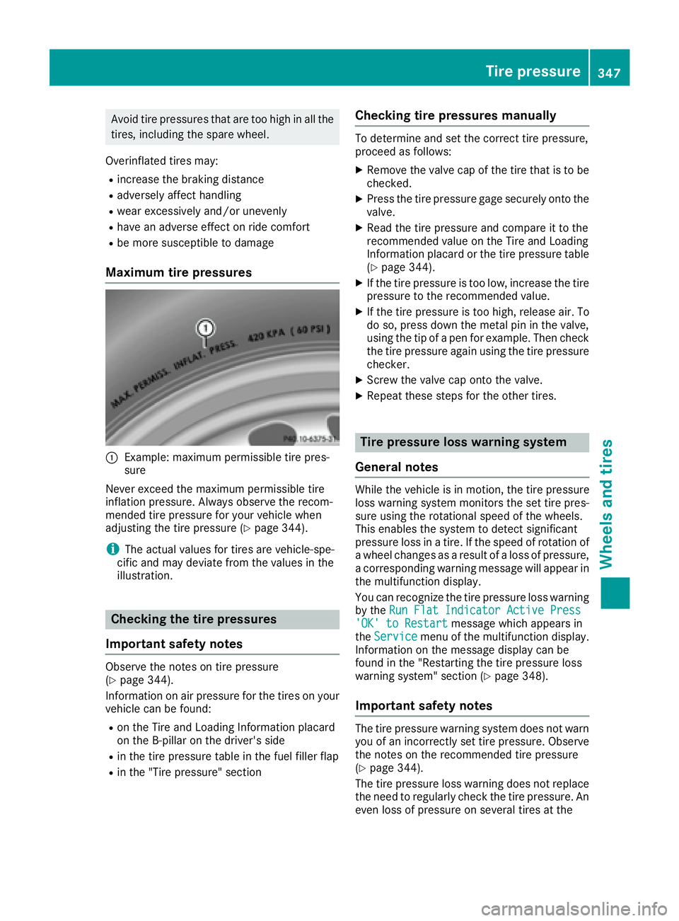
�C
Example: maximum permissible tire pres-
sure
Never exceed the maximum permissible tire
inflation pressure. Always observe the recom-
mended tire pressure for your vehicle when
adjusting the tire pressure ( Y
page 344).
i The actual values for tires are vehicle-spe-
cific and may deviate from the values in the
illustration.
Checking the tire pressures
Important safety notes Observe the notes on tire pressure
( Y
page 344).
Information on air pressure for the tires on your
vehicle can be found: R
on the Tire and Loading Information placard
on the B-pillar on the driver's side R
in the tire pressure table in the fuel filler flap R
in the "Tire pressure" section Checking tire pressures manually To determine and set the correct tire pressure,
proceed as follows: X
Remove the valve cap of the tire that is to be
checked. X
Press the tire pressure gage securely onto the
valve. X
Read the tire pressure and compare it to the
recommended value on the Tire and Loading
Information placard or the tire pressure table
( Y
page 344). X
If the tire pressure is too low, increase the tire
pressure to the recommended value. X
If the tire pressure is too high, release air. To
do so, press down the metal pin in the valve,
using the tip of a pen for example. Then check
the tire pressure again using the tire pressure
checker. X
Screw the valve cap onto the valve. X
Repeat these steps for the other tires.
Tire pressure loss warning system
General notes While the vehicle is in motion, the tire pressure
loss warning system monitors the set tire pres-
sure using the rotational speed of the wheels.
This enables the system to detect significant
pressure loss in a tire. If the speed of rotation of
a wheel changes as a result of a loss of pressure,
a corresponding warning message will appear in
the multifunction display.
You can recognize the tire pressure loss warning
by the Run Flat Indicator Active Press
'OK' to Restart message which appears in
the Service menu of the multifunction display.
Information on the message display can be
found in the "Restarting the tire pressure loss
warning system" section ( Y
page 348).
Important safety notes
The tire pressure warning system does not warn
you of an incorrectly set tire pressure. Observe
the notes on the recommended tire pressure
( Y
page 344).
The tire pressure loss warning does not replace
the need to regularly check the tire pressure. An
even loss of pressure on several tires at the Tire pressure 347
Wheels and tires Z